

SGS Thomson Microelectronics STPS60L40CW Datasheet

®
STPS60L40CW
LOW DROP POWER SCHOTTK Y RECTIFIER
MAIN PRODUCTS CHARACTE RISTICS
I
F(AV)
V
RRM
2 x 30 A
40 V
Tj (max) 150°C
V
(max) 0.50 V
F
FEATURES AND BENE FITS
LOW FORWARD VOLTAGE DROP FOR LESS
POWER DISSIPATION
NEGLIGIBLE SWITCHING LO SSES ALLOWING
HIGH FREQUENCY OPERATION
AVALANCHE RATED
DESCRIPTION
Dual center tap Schottky barrier rectifier designed
for high frequency Switched Mode Power Supplies
and DC to DC converters.
Packaged in TO-247 this device is intended for
use in low voltage, high frequency inverters,
free-wheeling and polarity protection applications.
ABSOLUTE RATINGS (limiting values, per diode)
A1
K
A2
A2
K
A1
TO-247
Symbol Parameter Value Unit
V
RRM
I
F(RMS)
I
F(AV)
I
FSM
I
RRM
I
RSM
T
stg
Tj
dV/dt
dPtot
* :
dTj
July 1999 - Ed: 4A
Repetitive peak reverse voltage
RMS forward current
Average forward current Tc = 135°C
Surge non repetitive forward current tp = 10 ms Sinusoidal
Repetitive peak reverse current tp=2 µs square F=1kHz
Non repetitive peak reverse current tp = 100 µs square
Storage temperature range
Maximum operating junction temperature *
Critical rate of rise of reverse voltage
<
Rth(j
δ = 0.5
1
thermal runaway condition for a diode on its own heatsink
a
−
)
Per diode
Per device
40 V
50 A
30 A
60
600 A
2A
4A
- 65 to + 150 °C
150 °C
10000 V /µs
1/4
STPS60L40CW
THERMA L RE SISTA NC ES
Symbol Parameter Value Unit
R
R
th (j-c)
th(c)
Junction to case Per diode
Total
Coupling
0.75
0.42
0.1 °C/W
°C/W
When the diodes 1 and 2 are used simultaneously :
∆ Tj(diode 1) = P(diode1) x R
(Per diode) + P(diode 2) x R
th(j-c)
th(c)
STATIC ELECTRICAL CHARACTE RISTICS (per diode)
Symbol Parameter Tests Conditions Min. Typ. Max. Unit
I
*
R
V
F
Reverse leakage
current
*
Forward voltage drop Tj = 25°CI
Tj = 25°CV
Tj = 100°C
Tj = 125°CI
Tj = 25°CI
Tj = 125°CI
= V
R
= 30 A
F
= 30 A
F
= 60 A
F
= 60 A
F
RRM
30 110 mA
0.44 0.5
0.64 0.72
1.5 mA
0.55 V
0.73
Pulse test : * tp = 380 µs, δ < 2%
To evaluate the maximum conduction losses use the following equation :
P = 0.28 x I
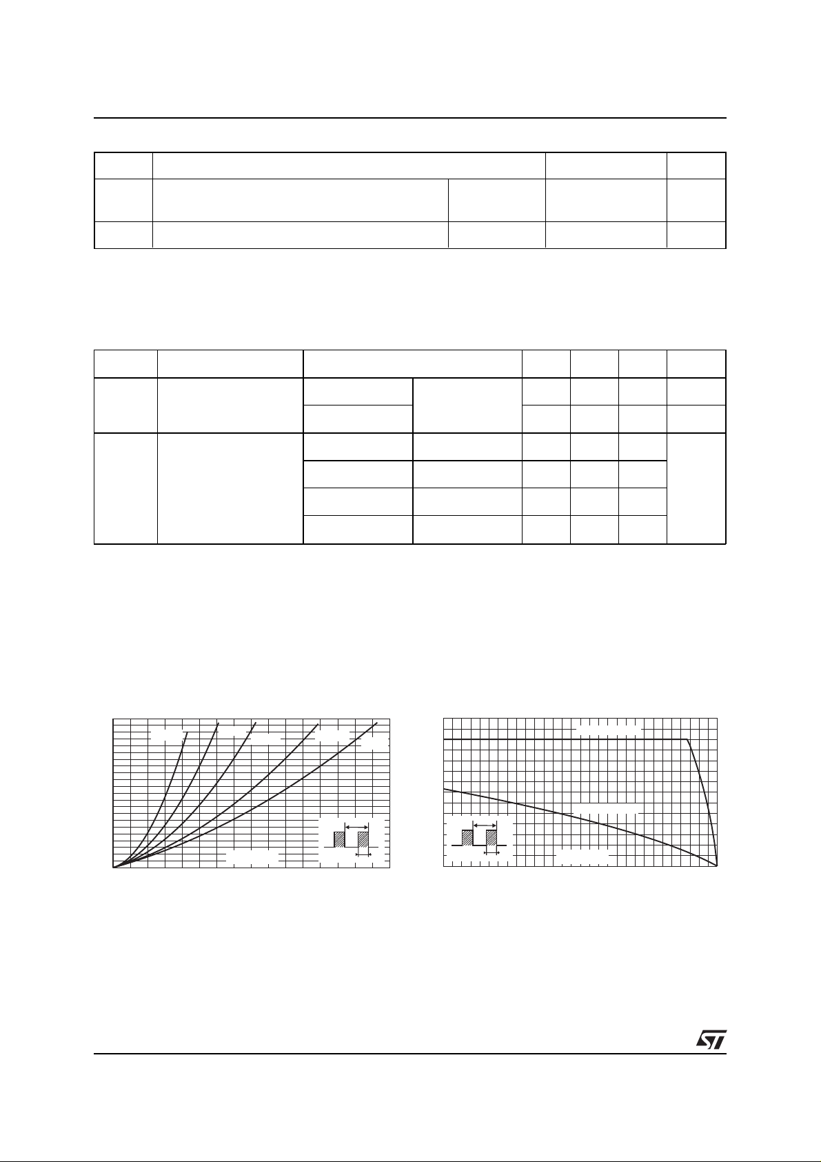
Fig. 1: Average forward power dissipation versus
average forward current (per diode).
PF(av)(W)
22
20
18
16
14
12
10
8
6
4
2
0
0 5 10 15 20 25 30 35 40
F(AV)
δ = 0.05
+ 0.0073 I
δ = 0.1
IF(av) (A)
F2(RMS)
δ = 0.2
δ = 0.5
δ
=tp/T
Fig. 2: Average current versus ambient
temperature (δ = 0.5) (per diode).
IF(av)(A)
35
δ = 1
T
tp
30
25
20
15
δ
=tp/T
T
tp
10
5
0
0 25 50 75 100 125 150
Rth(j-a)=Rth(j-c)
Rth(j-a)=15°C/W
Tamb(°C)
2/4
 Loading...