

SGS Thomson Microelectronics STPS6045CPI, STPS6045CW, STPS6045CP Datasheet
STPS6045CP/CPI/CW
POWER SCHOTTKY RECTIFIER
MAINPRODUCTCHARACTERISTICS
I
F(AV)
V
RRM
2x30 A
45 V
Tj (max) 175 °C
(max) 0.63 V
V
F
FEATURESAND BENEFITS
VERYSMALLCONDUCTION LOSSES
NEGLIGIBLESWITCHINGLOSSES
EXTREMEFAST SWITCHING
LOWTHERMALRESISTANCE
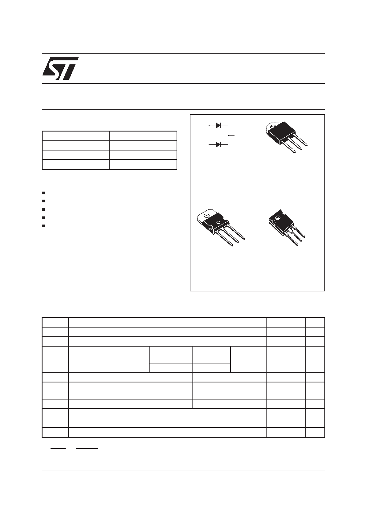
INSULATEDPACKAGE:TOP-3I
Insulatingvoltage = 2500V
RMS
Capacitance= 12pF
DESCRIPTION
Dual center tap Schottky rectifier suited for
switchmodepowersupply and high frequencyDC
toDCconverters.
Packaged either in SOT-93, TOP-3I or TO-247,
thisdeviceisintendedfor usein lowvoltage,high
frequency inverters, free wheeling and polarity
protectionapplications.
ABSOLUTERATINGS
(limiting values,per diode)
A1
A2
SOT-93
STPS6045CP
A1
K
A2
K
A1
Insulated
TOP-3I
STPS6045CPI
A2
K
A2
K
A1
TO-247
STPS6045CW
Symbol Parameter Value Unit
V
RRM
I
F(RMS)
I
F(AV)
I
FSM
I
RRM
Repetitivepeakreverse voltage
RMSforwardcurrent
Averageforwardcurrent
δ =0.5
SOT-93
TO-247
TOP-3I
Tc = 150°C Per diode
Tc = 130°C Perdevice
Surgenon repetitiveforwardcurrent tp = 10 mssinusoidal
RepetitivePeakreverse current tp = 2 µs square
45 V
60 A
30 A
60
400 A
1A
F = 1kHz
I
RSM
Tstg
Tj
dV/dt
dPtot
*:
dTj
June 1999 - Ed:5B
Non repetitivepeak reversecurrent tp = 100 µssquare
Storagetemperaturerange
Maximumoperatingjunction temperature*
Criticalrate of rise of reversevoltage
<
Rth(j−a
1
thermal runawayconditionfor adiodeon itsownheatsink
)
3A
- 65 to+ 175 °C
175 °C
10000 V/µs
1/5
STPS6045CP/CPI/CW
THERMAL RESISTANCES
Symbol Parameter Value Unit
R
th (j-c)
Junctionto case
SOT-93/ TO-247
Perdiode
Total
TOP-3I
Perdiode
Total
R
th (c)
SOT-93/ TO-247
Coupling
TOP-3I 0.4
Whenthe diodes1 and2 are used simultaneously:
(diode1) = P(diode1)x R
∆ T
J
(Perdiode)+ P(diode2) x R
th(j-c)
th(c)
STATICELECTRICALCHARACTERISTICS (per diode)
Symbol Parameter TestsConditions Min. Typ. Max. Unit
*
I
R
V
F
Reverseleakage
current
*
Forwardvoltage drop Tj= 125°CI
Tj= 25°CV
Tj= 125°C
Tj= 25°CI
Tj= 125°CI
R=VRRM
=30A
F
=60A
F
=60A
F
0.95
°C/W
0.55
1.8
1.1
0.15
500 µA
20 80 mA
0.53 0.63 V
0.84
0.68 0.78
Pulsetest : **tp = 380 µs,
δ <2%
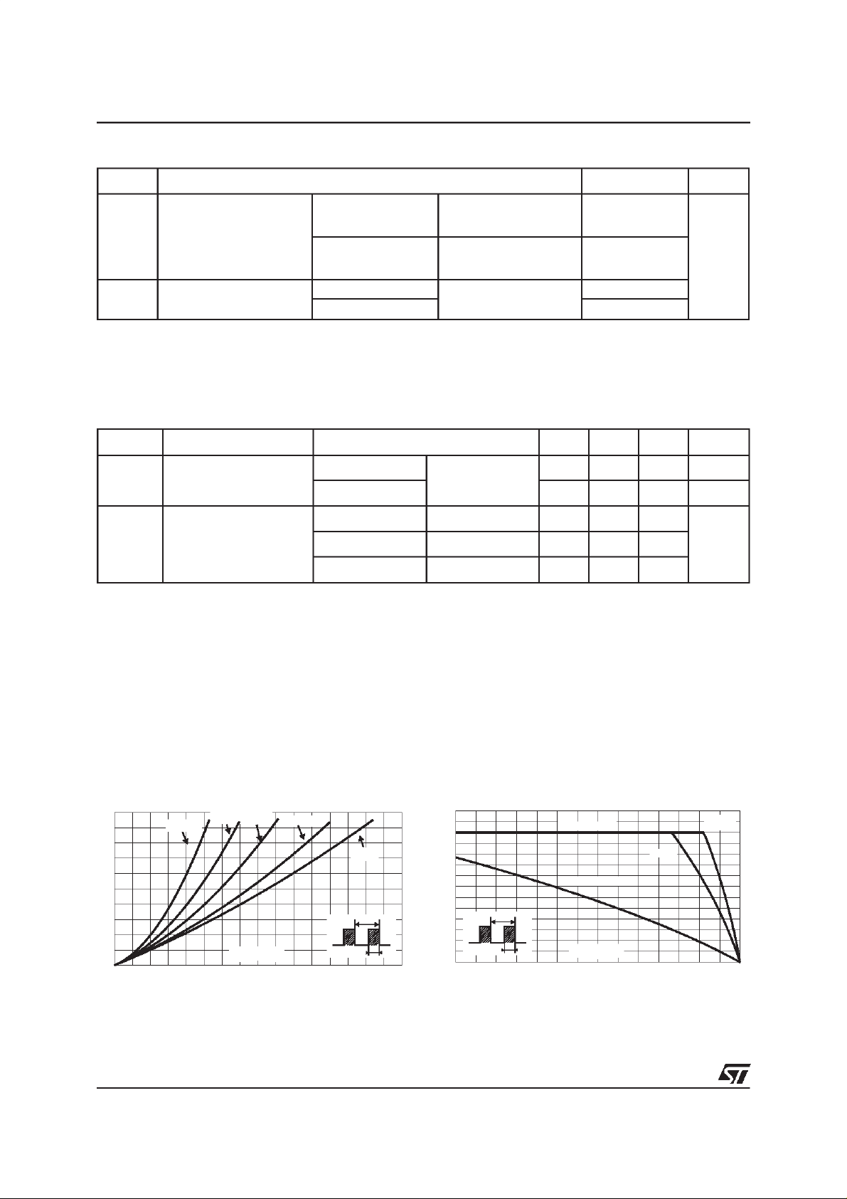
Toevaluate theconductionlossesuse thefollowingequation:
P= 0.48x I
Fig. 1:
versus averageforward current(per diode).
PF(av)(W)
25
20
15
10
5
0
0 5 10 15 20 25 30 35 40
+ 0.005I
F(AV)
F2(RMS)
Average forward power dissipation
δ = 0.05
δ = 0.2δ = 0.1
IF(av) (A)
δ= 0.5
δ
=tp/T
δ =1
T
tp
Fig. 2: Average current versus ambi ent
temperature (δ=0.5 , per diode).
IF(av)(A)
35
30
25
20
15
10
5
0
0 25 50 75 100 125 150 175
δ
=tp/T
Rth(j-a)=Rth(j-c)
TOP-3I
Rth(j-a)=10°C/W
T
tp
Tamb(°C)
SOT-93
TO-247
2/5
 Loading...