

SGS Thomson Microelectronics STPS40L15CT, STPS40L15CW Datasheet
®
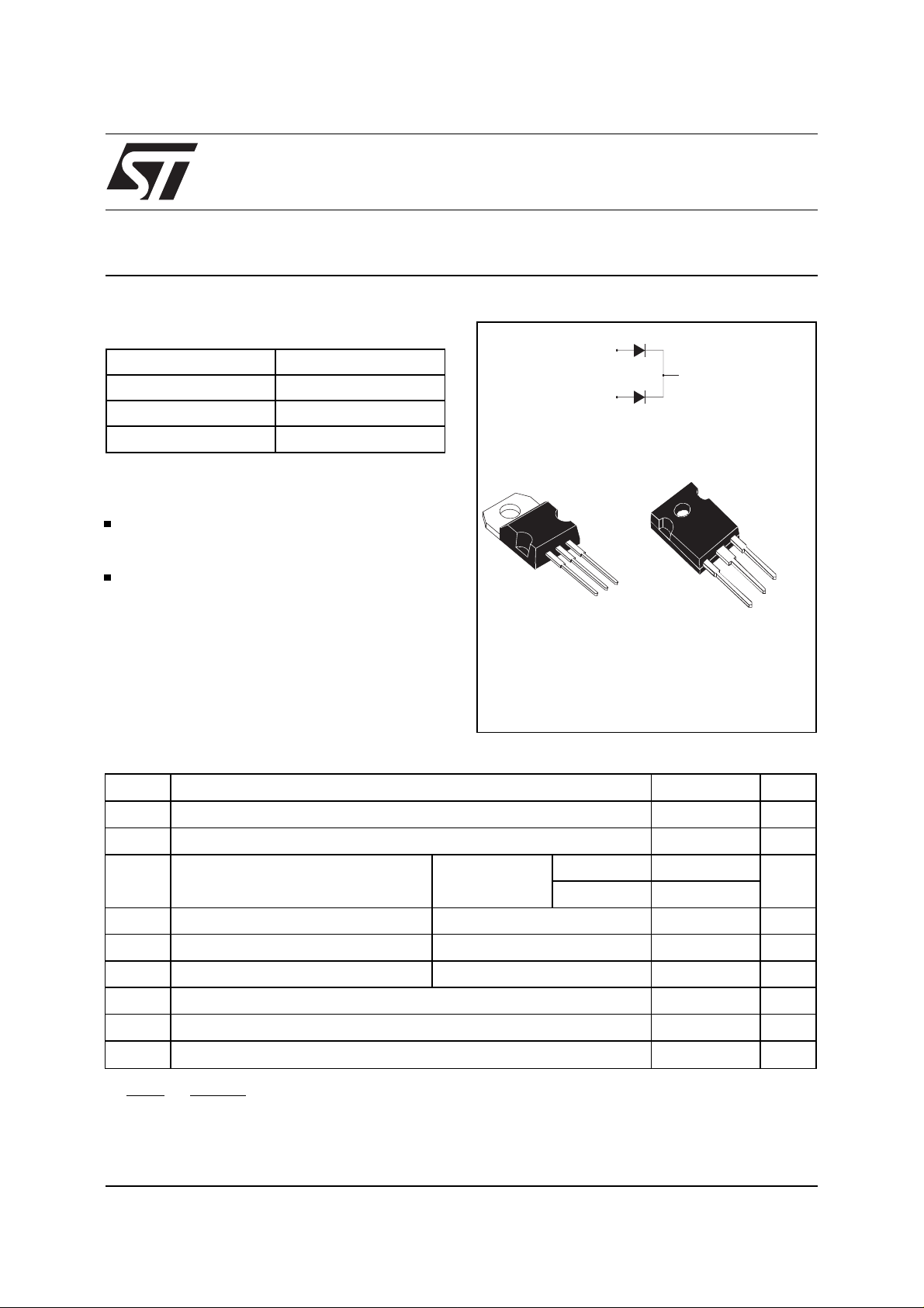
LOW DROP OR-ing POW ER SCHOTTKY DIOD E
MAJOR PRODUCT CHARACTE RISTICS
I
F(AV)
V
RRM
Tj (max) 150°C
V
(max) 0.33 V
F
FEATURES AND BENEFITS
VERY LOW F O RWARD VO LTAGE DROP FOR
LESS POWER DISSIPATION AND REDUCED
HEATSINK SIZE
REVERSE VOLTAGE SUITED TO OR-ing OF
3V, 5V and 12V RA ILS
DESCR IPT ION
2 x 20 A
15 V
STPS40L15CW/CT
A1
K
A2
A2
K
A1
A1
A2
K
Dual center tap schottky rectifier packaged in
TO-220AB and TO-247, this device is especially
intended for use as OR-ing diode in fault tolerant
TO-220AB
STPS40L15CT
TO-247
STPS40L15CW
power supply equipments.
ABSOLUTE RATINGS (limiting values, per diode)
Symbol Parameter Value Unit
V
RRM
I
F(RMS)
I
F(AV)
I
FSM
I
RRM
I
RSM
T
stg
T
j
dV/dt
dPtot
* :
dTj
Repetitive peak reverse voltage
RMS forward current
Average forward current Tcase = 140°C
δ = 1
Surge non repetitive forward current tp = 10 ms Sinusoidal
Peak repetitive reverse current tp = 2 µs F = 1kHz
Non repetitive peak reverse current tp = 100 µs
Storage temperature range
Maximum operating junction temperature *
Critical rate of rise of reverse voltage
<
1
Rth(j−a
thermal runaway condition for a diode on its own heatsink
)
Total
Per diode
15 V
30 A
40 A
20
310 A
2A
3A
- 65 to + 150 °C
150 °C
10000 V/µs
November 1999 - Ed: 4A
1/5
STPS40L15CW/CT
THERMA L RE SISTA NC ES
Symbol Parameter Value Unit
(j-c)
R
R
th
th (c)
Junction to case
STATIC ELECTRICAL CHARACTE RISTICS (Per diode)
Symbol Parameter Tests Conditions Min. Typ. Max. Unit
Per diode 1.6 °C/W
Total 0.85
Coupling 0.1 °C/W
*
I
R
V
F
Reverse leakage
current
*
Forward voltage drop Tj = 25°CI
Tj = 25°CV
Tj = 100°C
Tj = 25°CI
Tj = 125°C I
= V
R
= 19 A
F
= 40 A
F
= 19 A
F
Tj = 125°C IF = 40 A
Pulse test : * tp = 380 µs, δ < 2%
To evaluate the conduction losses use the following equation :
P = 0.18 x I
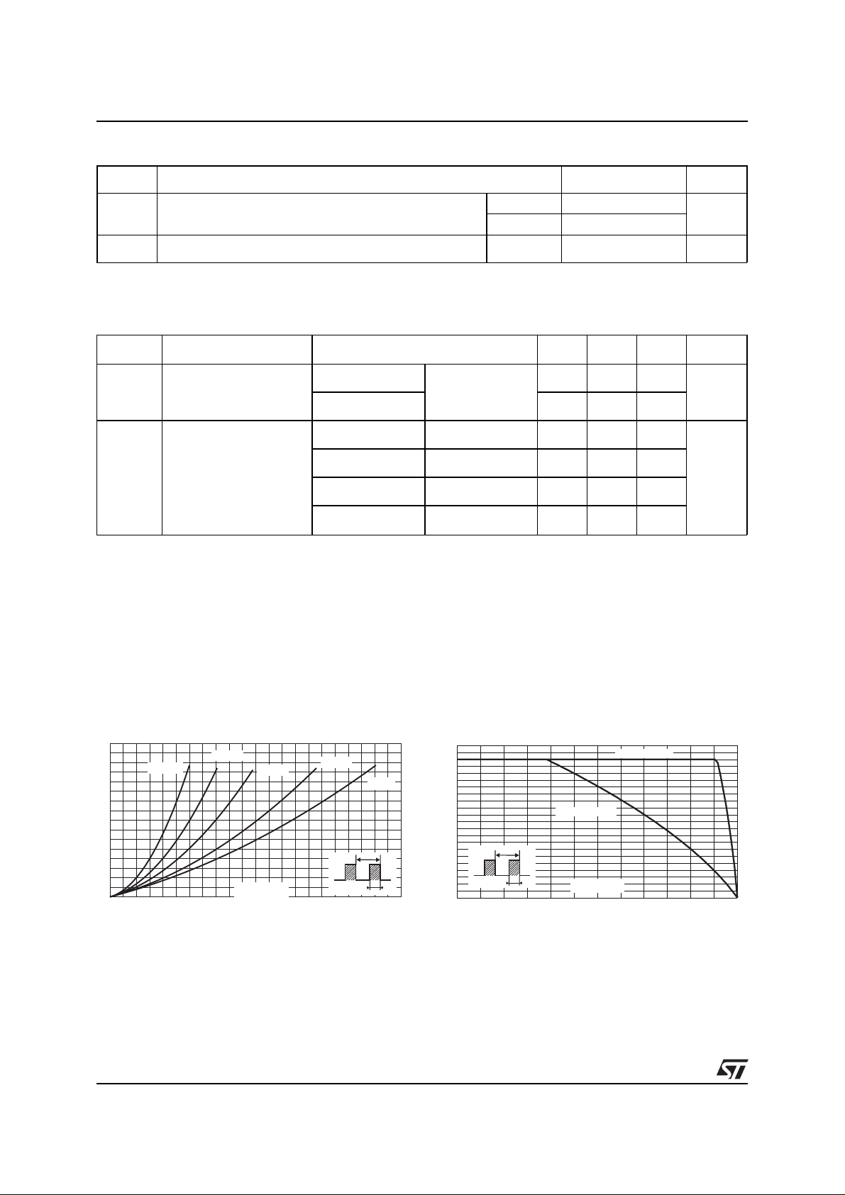
Fig. 1: Average forward power dis sipation versus
average forward current (per diode).
PF(av)(W)
8
7
6
5
4
3
2
1
0
0 2 4 6 8 10121416182022
δ = 0.05
F(AV)
+ 0.008 I
δ = 0.1
IF(av) (A)
F2(RMS )
δ = 0.2
δ = 0.5
δ
=tp/T
T
δ = 1
Fig. 2: Average forward current versus ambient
temperature (δ=1, per diode).
IF(av)(A)
22
20
18
16
14
12
10
8
6
4
tp
2
0
0 25 50 75 100 125 150
RRM
=tp/T
δ
6mA
200 500
0.41 V
0.52
0.28 0.33
0.42 0.50
Rth(j-a)=Rth(j-c)
Rth(j-a)=15°C/W
T
tp
Tamb(°C)
2/5
 Loading...