

SGS Thomson Microelectronics STPS30L45CW, STPS30L45CR, STPS30L45CT, STPS30L45CFP Datasheet
®
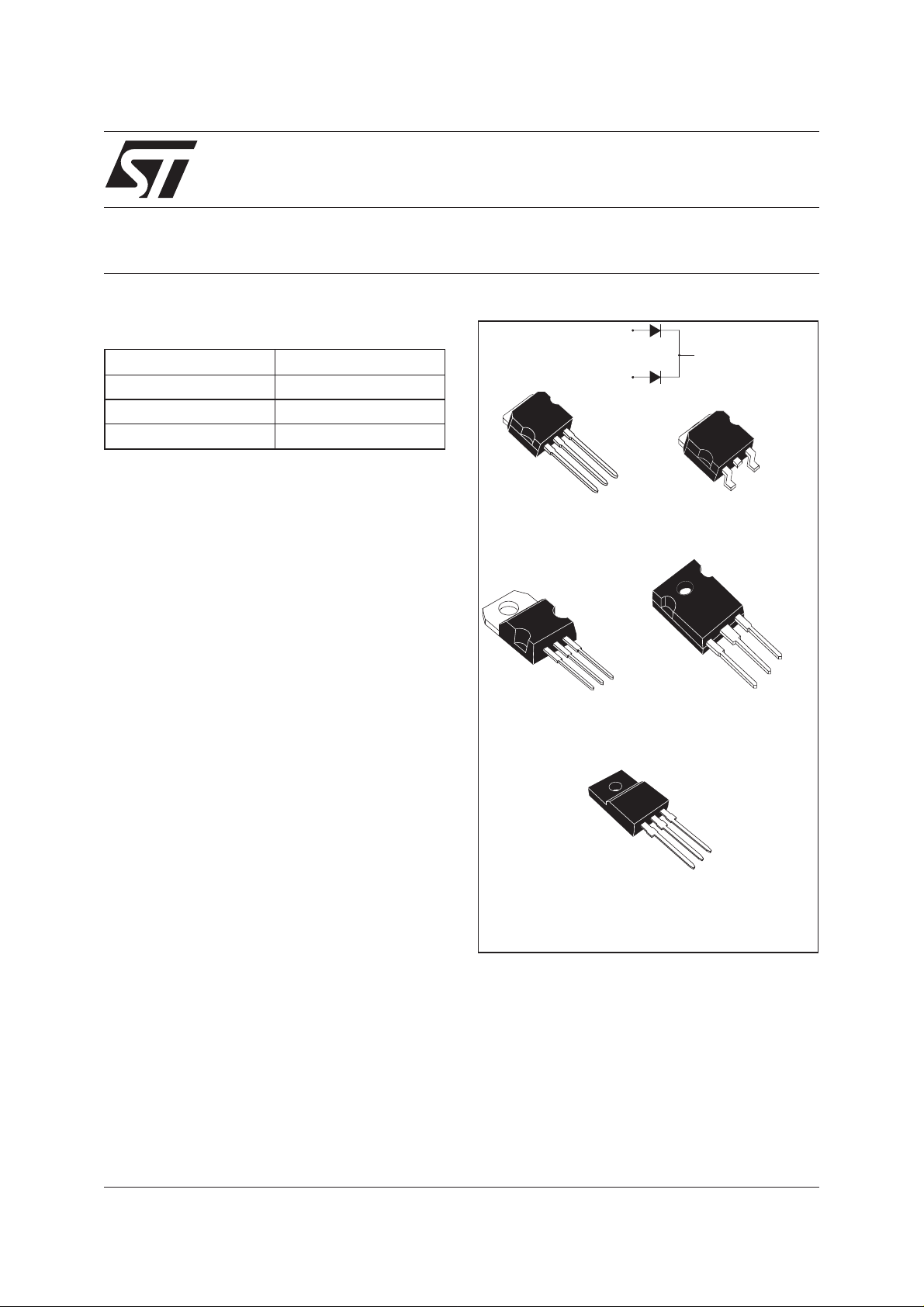
STPS30L45CG/CR/CT/CW/CFP
LOW DROP POWER SCHOTTKY RECTIFIER
MAIN PRODUCTS CHARACTERISTICS
I
F(AV)
V
RRM
2x15A
45 V
Tj (max) 150 °C
V
(max) 0.50 V
F
FEATURES AND BENEFITS
LOW FORWARD VOLTAGE DROP MEANING
■
VERY SMALL CONDUCTION LOSSES
LOW SWITCHING LOSSES ALLOWING HIGH
■
FREQUENCY OPERATION
LOW THERMAL RESISTANCE
■
■ AVALANCHERATED
■ INSULATEDPACKAGE: TO-220FPAB
Insulating voltage: 2000V DC
Capacitance = 45pF
■ AVALANCHECAPABILITY SPECIFIED
DESCRIPTION
Dual center tap schottky rectifiers suited for
Switched Mode Power Supplies and high
frequency DC to DC converters.
Packaged in TO-247, TO-220AB, TO-220FPAB,
2
PAK and I2PAK these devices are intended for
D
use in low voltage, high frequency inverters,
free-wheeling and polarity protection applications.
K
I2PAK
STPS30L45CR
A1
TO-220AB
STPS30L45CT
A1
A2
K
A2
A1
STPS30L45CG
A2
K
STPS30L45CW
A1
TO-220FPAB
STPS30L45CFP
K
A1
D2PAK
TO-247
A2
K
A2
A2
K
A1
July 2003 - Ed: 3B
1/8

STPS30L45CG/CR/CT/CW/CFP
ABSOLUTE RATINGS (limiting values, per diode)
Symbol Parameter Value Unit
V
RRM
I
F(RMS)
I
F(AV)
Repetitive peak reverse voltage
RMS forward current
Average forward
current
I
FSM
I
RRM
I
RSM
P
ARM
T
stg
Tj
dV/dt
Surge non repetitive forward current tp = 10 ms Sinusoidal
Repetitive peak reverse current tp=2µs square F=1kHz
Non repetitive peak reverse current tp = 100 µs square
Repetitive peak avalanche power tp = 1µs Tj = 25°C
Storage temperature range
Maximum operating junction temperature *
Critical rate of rise of reverse voltage
TO-220FPAB Tc = 110°C
δ = 0.5
TO-220AB, TO-247,
2
I
PAK, D2PAK
Tc = 135°C
δ = 0.5
Per diode
Per device
45 V
30 A
15
30
220 A
1A
3A
6000 W
- 65 to + 150 °C
150 °C
10000 V/µs
A
dPtot
*:
<
dTj Rth j a
thermal runaway condition for a diode on its own heatsink
−1()
THERMAL RESISTANCES
Symbol Parameter Value Unit
R
R
th (j-c)
th (c)
Junction to case TO-220FPAB
TO-220AB, TO-247,
2
I
PAK, D2PAK
TO-220FPAB
TO-220AB, TO-247,
2
I
PAK, D2PAK
Per diode
Total
Per diode
Total
Coupling 2.5 °C/W
4
3.2
1.60
0.85
0.10
°C/W
When the diodes 1 and 2 are used simultaneously :
∆ Tj(diode 1) = P(diode1) x R
(Per diode) + P(diode 2) x R
th(j-c)
th(c)
STATIC ELECTRICAL CHARACTERISTICS (per diode)
Symbol Parameter Tests Conditions Min. Typ. Max. Unit
*
I
R
Reverse leakage
current
V
*
F
Pulse test : * tp = 380 µs, δ <2%
Forward voltage drop Tj= 25°CI
Tj = 25°C V
R=VRRM
Tj = 125°C
=15A
F
Tj = 125°C I
Tj=25°CI
Tj = 125°C I
=15A
F
=30A
F
=30A
F
100 200 mA
0.42 0.50
0.59 0.67
0.4 mA
0.55 V
0.74
To evaluate the conduction losses use the following equation :
P = 0.330 x I
2/8
F(AV)
+ 0.011 I
F2(RMS)
STPS30L45CG/CR/CT/CW/CFP
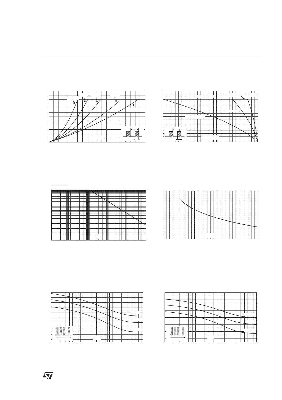
Fig. 1: Average forward power dissipation versus
average forward current (per diode).
PF(av)(W)
12
10
8
δ = 0.05
δ = 0.1
δ = 0.2
δ = 0.5
δ = 1
6
4
T
2
0
IF(av) (A)
02468101214161820
δ
=tp/T
tp
Fig. 3: Normalized avalanche power derating
versus pulse duration.
P(t)
ARM p
P (1µs)
ARM
1
0.1
0.01
t (µs)
0.001
0.10.01 1
p
10 100 1000
Fig. 2: Average forward current versus ambient
temperature (δ=0.5, per diode).
IF(av)(A)
18
16
Rth(j-a)=Rth(j-c)
TO-220AB/TO-247/I²PAK/D²PAK
14
12
10
8
6
4
2
=tp/T
δ
0
0 25 50 75 100 125 150
T
Rth(j-a)=15°C/W
tp
Tamb(°C)
TO-220FPAB
Fig. 4: Normalized avalanche power derating
versus junction temperature.
P(t)
ARM p
P (25°C)
ARM
1.2
1
0.8
0.6
0.4
0.2
0
0 25 50 75 100 125 150
T (°C)
j
Fig. 5-1:Nonrepetitivesurgepeak forward current
versus overload duration (maximum values, per
diode).
IM(A)
200
180
160
140
120
100
80
60
IM
40
20
0
1E-3 1E-2 1E-1 1E+0
δ=0.5
t
t(s)
Tc=25°C
Tc=75°C
Tc=125°C
Fig. 5-2: Non repetitive surge peak forward current
versus overload duration (maximum values, per
diode) (TO-220FPAB only).
IM(A)
140
120
100
80
60
40
IM
20
0
1E-3 1E-2 1E-1 1E+0
δ=0.5
t
t(s)
Tc=25°C
Tc=75°C
Tc=125°C
3/8
 Loading...