

SGS Thomson Microelectronics STPS30L40CT, STPS30L40CW, STPS30L40CG Datasheet
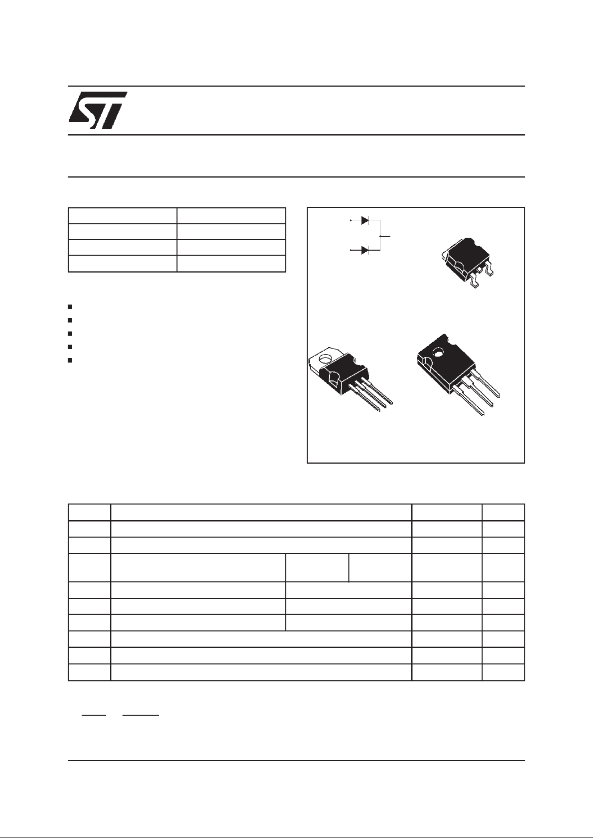
LOW DROPPOWER SCHOTTKY RECTIFIER
MAINPRODUCTSCHARACTERISTICS
STPS30L40CG/CT/CW
I
F(AV)
V
RRM
2 x 15A
40 V
Tj (max) 150 °C
V
(max) 0.50 V
F
FEATURESAND BENEFITS
VERYSMALLCONDUCTION LOSSES
NEGLIGIBLESWITCHINGLOSSES
LOWFORWARD VOLTAGEDROP
LOWTHERMALRESISTANCE
AVALANCHERATED
DESCRIPTION
Dual center tap schottky rectifiers suited for
Switched Mode Power Supplies and high
frequencyDC to DCconverters.
2
PackagedinTO-247,TO-220ABandD
PAKthese
devicesare intended for use in low voltage,high
frequency inverters, free-wheeling and polarity
protectionapplications.
ABSOLUTE RATINGS
(limitingvalues,per diode)
A1
A2
A1
TO-220AB
STPS30L40CT
K
K
A2
A1
2
PAK
D
STPS30L40CG
A2
K
A2
K
A1
TO-247
STPS30L40CW
Symbol Parameter Value Unit
V
RRM
I
F(RMS)
I
F(AV)
I
FSM
I
RRM
I
RSM
T
stg
Tj
dV/dt
dPtot
*:
dTj
July 1999 -Ed: 3A
Repetitivepeak reverse voltage
RMSforwardcurrent
Averageforward current Tc= 135°C
Surgenonrepetitiveforwardcurrent tp = 10 ms Sinusoidal
Repetitivepeak reverse current tp=2µs square F=1kHz
Non repetitivepeakreverse current tp = 100 µs square
Storagetemperaturerange
Maximumoperatingjunction temperature*
Criticalrateof riseofreversevoltage
<
Rth(j
δ =0.5
1
thermal runawayconditionfor a diode on its own heatsink
a
)
−
Per diode
Per device
40 V
30 A
15
30
220 A
1A
3A
- 65 to+ 150 °C
150 °C
10000 V/µs
A
1/6
STPS30L40CG/CT/CW
THERMAL RESISTANCES
Symbol Parameter Value Unit
R
th (j-c)
R
th (c)
Junctionto case
Whenthediodes1 and2 areused simultaneously:
∆ Tj(diode1)= P(diode1)x R
(Perdiode) + P(diode2)x R
th(j-c)
Per diode
Total
Coupling 0.10 °C/W
th(c)
1.60
0.85
°C/W
STATICELECTRICALCHARACTERISTICS
(per diode)
Symbol Parameter TestsConditions Min. Typ. Max. Unit
*
I
R
V
F
Reverseleakage
current
*
Forward voltagedrop Tj =25°CI
Tj = 25°CV
Tj = 100°C
Tj = 125°CI
Tj = 25°CI
Tj = 125°CI
R=VRRM
=15A
F
=15A
F
=30A
F
=30A
F
20 50 mA
0.42 0.50
0.59 0.67
360 µA
0.55 V
0.74
Pulsetest: * tp = 380µs,δ<2%
Toevaluatethe conductionlossesusethe followingequation:
P = 0.330 x I
F(AV)
+0.011I
F2(RMS)
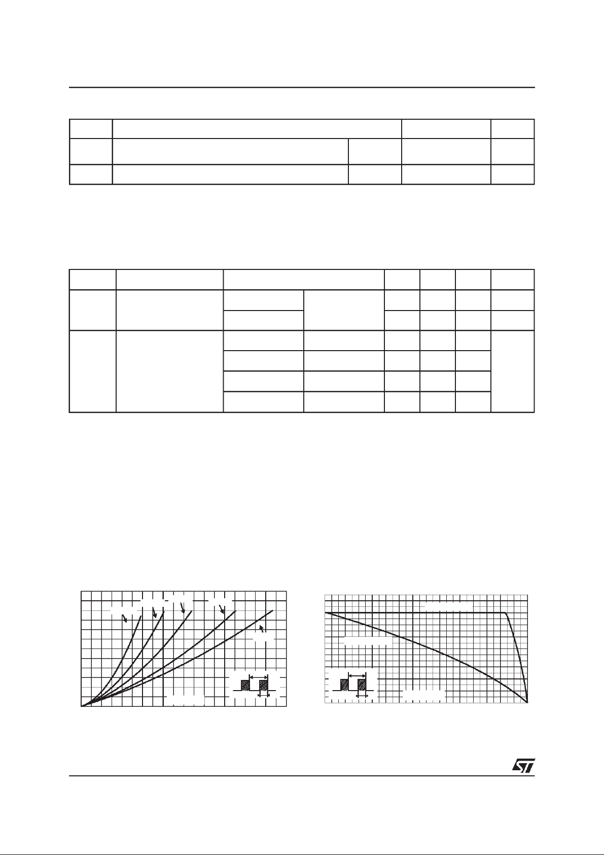
Fig. 1: Average forward power dissipation versus
averageforwardcurrent(per diode).
PF(av)(W)
12
10
8
6
4
2
0
02468101214161820
2/6
δ = 0.05
δ = 0.1
δ = 0.2
IF(av)A
δ= 0.5
δ =1
T
=tp/T tp
δ
Fig. 2:
Average current versus ambient
temperature(δ=0.5) (perdiode).
IF(av)(A)
18
16
14
12
10
Rth(j-a)=15°C/W
8
6
4
2
0
0 25 50 75 100 125 150
δ
=tp/T
T
tp
Rth(j-a)=Rth(j-c)
Tamb(°C)
 Loading...