

SGS Thomson Microelectronics STPS24045TV Datasheet
MAINPRODUCTCHARACTERISTICS
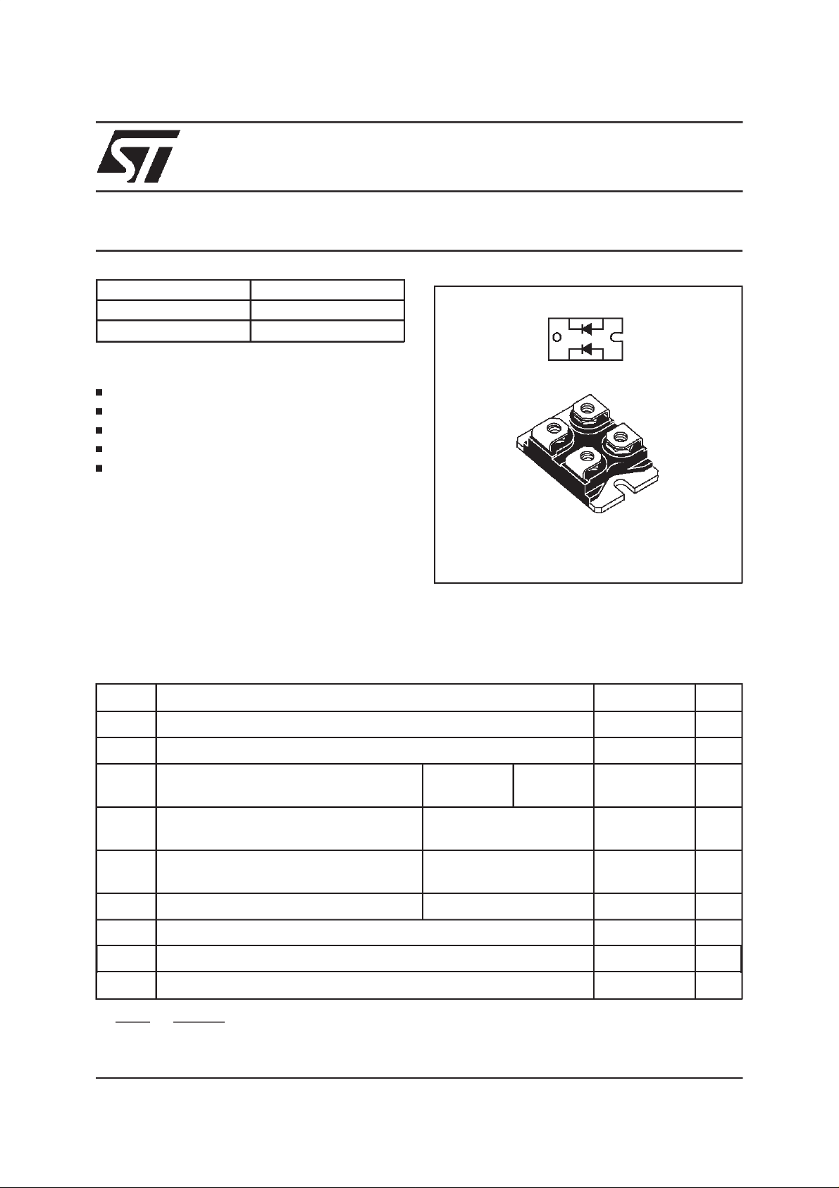
STPS24045TV
POWER SCHOTTKY RECTIFIER
I
F(AV)
V
RRM
V
(max) 0.67 V
F
FEATURESAND BENEFITS
2 x 120 A
45 V
K2 A2
A1K1
VERYSMALLCONDUCTION LOSSES
NEGLIGIBLESWITCHINGLOSSES
EXTREMELYFASTSWITCHING
LOWTHERMALRESISTANCE
INSULATEDPACKAGE:
Insulatingvoltage= 2500V
(RMS)
Capacitance= 45pF
DESCRIPTION
Dual power Schottky rectifier suited for Switched
ISOTOP
TM
Mode Power Supplies and high frequency DC to
DCconverters.
Packagedin ISOTOP, this device is especially intended for use in low voltage, high frequency in-
ISOTOPis a trademarkof STMicroelectronics
verters, free wheeling and polarity protection
applications.
ABSOLUTERATINGS(limiting values,per diode)
Symbol Parameter Value Unit
V
RRM
I
F(RMS)
I
F(AV)
I
FSM
Repetitivepeak reversevoltage 45 V
RMSforwardcurrent 170 A
Averageforward current Tc= 80°C
δ = 0.5
Surgenonrepetitiveforwardcurrent tp = 10 ms
Per diode
Per device
120
240
1500 A
Sinusoidal
I
RRM
Repetitivepeak reversecurrent tp = 2µs
2A
F = 1kHzsquare
I
RSM
T
stg
Non repetitivepeak reversecurrent tp = 100µs square 10 A
Storagetemperature range - 55 to+ 150 °C
Tj Maximumoperatingjunctiontemperature 150 °C
dV/dt Criticalrate of rise of reverse voltage 10000 V/µs
dPtot
*:
dTj
September 1999 - Ed : 3A
<
1
Rth(j−a
thermal runawayconditionfor a diodeon its ownheatsink
)
A
1/4
STPS24045TV
THERMALRESISTANCES
Symbol Parameter Value Unit
R
R
th (j-c)
th (c)
Junctionto case Perdiode 0.65
When the diodes 1 and 2are used simultaneously :
∆ Tj(diode 1) = P(diode)x R
(Per diode) + P(diode 2) x R
th(j-c)
Total 0.28
Coupling 0.10
th(c)
°
C/W
STATICELECTRICALCHARACTERISTICS
(per diode)
Symbol Parameter TestsConditions Min. Typ. Max. Unit
* Reverseleakage current Tj = 25°CV
I
R
R=VRRM
2mA
Tj = 125°C 300
* Forward voltagedrop Tj = 25°CI
V
F
Tj = 125°CI
Tj = 125°CI
Pulse test : * tp = 5 ms,δ<2%
** tp = 380 µs,δ <2%
To evaluate the conduction losses use the following equation:
P = 0.47 x I
+ 0.00167 x I
F(AV)
F2(RMS)
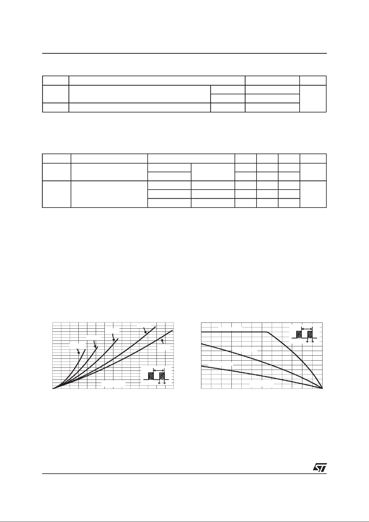
Fig. 1: Average forward power dissipation versus
averageforwardcurrent (perdiode).
PF(av)(W)
110
100
90
80
70
60
50
40
30
20
10
0
0 20 40 60 80 100 120 140
δ = 0.05
δ = 0.2
δ = 0.1
IF(av)(A)
δ= 0.5
δ
=tp/T
δ =1
T
tp
= 240A 0.91 V
F
= 240A 0.72 0.87
F
= 120A 0.52 0.67
F
Fig. 2: Average forward current versus ambient
temperature(δ= 0.5, perdiode).
IF(av)(A)
140
120
100
80
60
40
20
0
0 25 50 75 100 125 150
Rth(j-a)=Rth(j-c)
Rth(j-a)=2°C/W
Rth(j-a)=5°C/W
Tamb(°C)
δ
T
=tp/T
tp
2/4
 Loading...