

SGS Thomson Microelectronics STPS20L40CW, STPS20L40CT, STPS20L40CF Datasheet
LOW DROP POWER SCHOTTKY RECTIFIER
MAJORPRODUCTS CHARACTERISTICS
STPS20L40CF/CW/CT
I
F(AV)
V
RRM
2 x 10A
40 V
Tj (max) 150°C
(max) 0.5 V
V
F
FEATURESAND BENEFITS
LOW FORWARD VOLTAGE DROP MEANING
VERYSMALLCONDUCTIONLOSSES
LOW DYNAMIC LOSSES AS A RESULT OF
THESCHOTTKYBARRIER
AVALANCHERATED
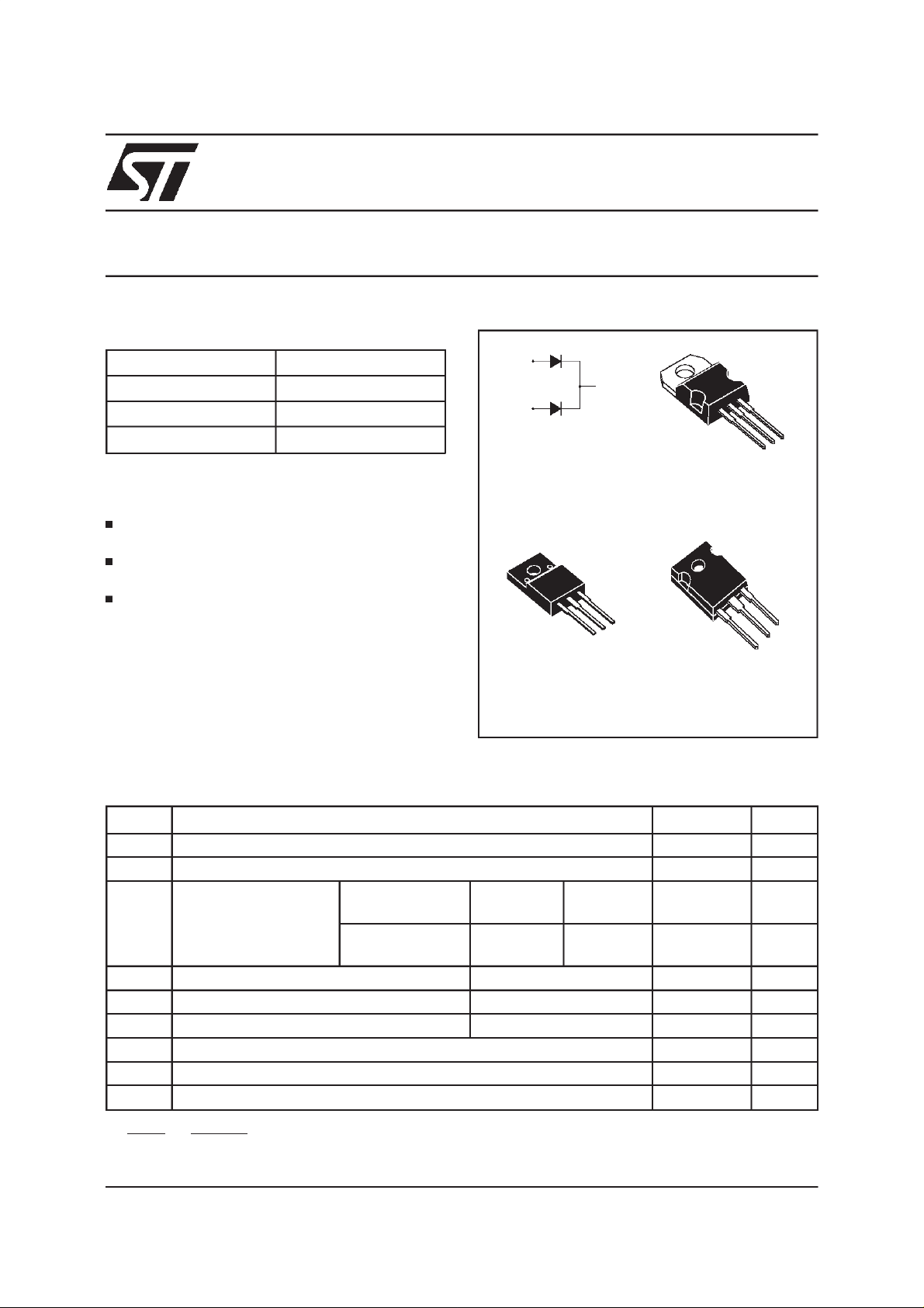
DESCRIPTION
Dual center tap Schottky rectifiers designed for
highfrequencyswitchedmodepower suppliesand
DC to DC converters.
Thesedevicesare intendedfor use in lowvoltage,
high frequency inverters, free-wheeling and
polarityprotectionapplications.
ABSOLUTE RATINGS(limiting values,per diode)
A1
K
A2
K
A1
ISOWATT220AB
STPS20L40CF
A2
A1
TO-220AB
STPS20L40CT
K
A1
TO-247
STPS20L40CW
K
A2
A2
Symbol Parameter Value Unit
V
RRM
I
F(RMS)
I
F(AV)
Repetitivepeak reversevoltage
RMSforward current
Averageforward
current
I
FSM
I
RRM
I
RSM
T
Tj
dV/dt
dPtot
*:
August 1999 - Ed: 3A
Surgenon repetitiveforward current tp= 10ms Sinusoidal
Peakrepetitive reversecurrent tp=2µs squareF=1kHz
Non repetitivepeak reversecurrent tp= 100µs square
stg
Storagetemperaturerange
Maximumoperatingjunction temperature*
Critical rate of riseof reversevoltage
1
<
dTj
Rth(j
TO-220AB
TO-247
ISOWATT220AB Tc= 115°C
thermal runawayconditionfor adiode on its own heatsink
a
)
−
Tc= 135°C
δ = 0.5
δ = 0.5
Per diode
Perdevice
Per diode
Perdevice
40 V
30 A
10
20
10
20
180 A
1A
2A
- 65 to +150 °C
150 °C
10000 V/µs
A
A
1/6
STPS20L40CF/CW/CT
THERMAL RESISTANCES
Symbol Parameter Value Unit
R
R
R
th(j-c)
th(j-c)
th(j-c)
Junctionto case ISOWATT220AB
Junctionto case TO-247
Junctionto case TO-220AB
Whenthe diodes1 and 2 are used simultaneously:
∆ Tj(diode1)= P(diode1)x R
(Per diode)+ P(diode2) x R
th(j-c)
Per diode
Total
Coupling
Per diode
Total
Coupling
Per diode
Total
Coupling
th(c)
4.5
3.5
2.5
2.2
1.20
0.3
2.2
1.3
0.3
°C/W
°C/W
°C/W
STATICELECTRICALCHARACTERISTICS
(per diode)
Symbol Parameter Tests Conditions Min. Typ. Max. Unit
I
R
VF*
*
Reverseleakage
current
Tj= 25°CV
Tj= 100°C
Forwardvoltagedrop Tj= 25°CI
Tj= 125°CI
Tj= 25°CI
Tj= 125°CI
R=VRRM
=10A
F
=10A
F
=20A
F
=20A
F
15 35 mA
0.44 0.5
0.62 0.72
0.7 mA
0.55 V
0.73
Pulsetest : *tp = 380 µs, δ <2%
To evaluatethe conductionlossesuse thefollowingequation:
P = 0.28x I
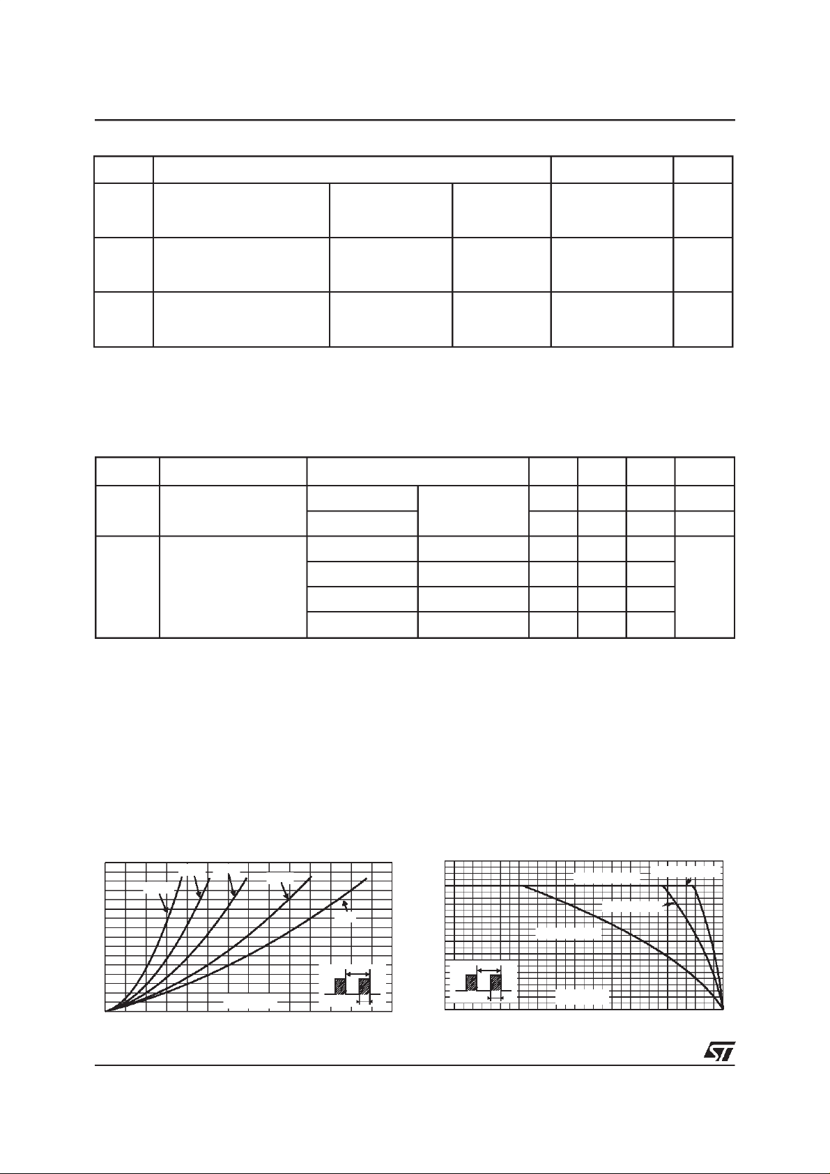
Fig. 1: Average forward power dissipation versus
averageforward current(perdiode).
F(AV)
+0.022 I
F2(RMS)
Fig. 2: Average forward current versus ambient
temperature(δ = 0.5, per diode).
PF(av)(W)
8
7
6
5
4
3
2
1
0
02468101214
2/6
δ= 0.05
δ = 0.1
δ = 0.2
IF(av) (A)
δ = 0.5
δ
δ =1
=tp/T
T
tp
IF(av)(A)
12
11
10
9
8
7
6
5
4
3
2
1
0
0 25 50 75 100 125 150
δ
=tp/T
T
tp
Rth(j-a)=Rth(j-c)
ISOWATT220AB
Rth(j-a)=15°C/W
Tamb(°C)
TO-220AB/TO-247
 Loading...