

SGS Thomson Microelectronics STPS2045CF, STPS2045CG, STPS2045CT Datasheet
MAINPRODUCTCHARACTERISTICS
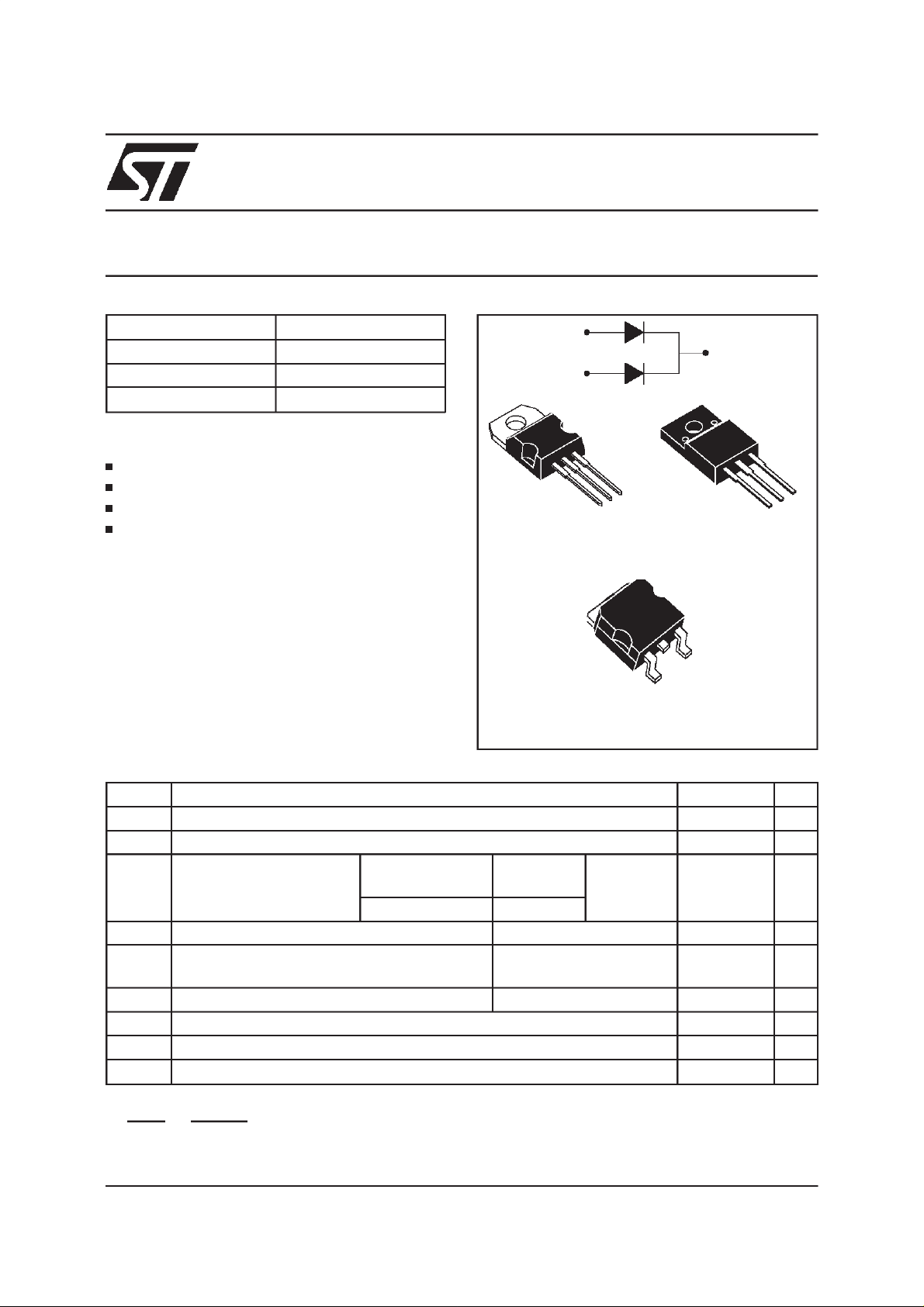
STPS2045CT/CF/CG
POWER SCHOTTKY RECTIFIER
I
F(AV)
V
RRM
2 x 10 A
45 V
Tj (max) 175 °C
(max) 0.57 V
V
F
FEATURESAND BENEFITS
VERYSMALLCONDUCTION LOSSES
NEGLIGIBLESWITCHINGLOSSES
EXTREMELYFAST SWITCHING
INSULATEDPACKAGE:ISOWATT220AB
Insulatingvoltage= 2000VDC
Capacitance= 12pF
DESCRIPTION
DualcentertapSchottkyrectifiersuited forSwitchModePowerSupplyandhighfrequencyDC to DC
converters.
Packaged either in TO-220AB, ISOWATT220AB
2
PAK, this device is especially intended for
or D
use in low voltage, high frequency inverters, free
wheelingand polarityprotectionapplications.
ABSOLUTE RATINGS(limitingvalues, per diode)
A1
A2
A1
TO-220AB
STPS2045CT
K
STPS2045CG
K
A2
K
A1
A2
K
ISOWATT220AB
STPS2045CF
A2
A1
2
PAK
D
Symbol Parameter Value Unit
V
RRM
I
F(RMS)
I
F(AV)
Repetitivepeak reversevoltage 45 V
RMSforward current 30 A
Averageforwardcurrent
δ
=0.5
TO-220AB
2
PAK
D
Tc = 155°C Per diode 10 A
ISOWATT220AB Tc = 125°C Per device 20
I
FSM
I
RRM
Surgenon repetitive forwardcurrent tp = 10 ms sinusoidal 180 A
Repetitivepeak reversecurrent tp = 2 µs square
1A
F = 1kHz
I
RSM
Nonrepetitivepeak reversecurrent
tp = 100 ms square
2A
Tstg Storagetemperaturerange -65 to +175 °C
Tj Maximumoperatingjunction temperature* 175 °C
dV/dt Criticalrateof rise of reversevoltage 10000 V/µs
<
1
Rth(j−a
thermal runawayconditionfor a diode on its own heatsink
)
dPtot
*:
dTj
June 1999 - Ed: 3B
1/7

STPS2045CT/CF/CG
THERMALRESISTANCES
Symbol Parameter Value Unit
R
R
th (j-c)
th (c)
Junctionto case TO-220AB/ D2PAK Perdiode
Total
ISOWATT220AB Perdiode
Total
TO-220AB/ D2PAK Coupling 0.3
2.2
1.3
4.5
3.5
°
ISOWATT220AB 2.5
Whenthe diodes1 and 2 are used simultaneously:
∆ Tj (diode1) = P (diode1)x R
STATICELECTRICAL CHARACTERISTICS
(perdiode) + P (diode2) x R
th(j-c)
(Per diode)
th(c)
Symbol Parameter Tests Conditions Min. Typ. Max. Unit
I
* Reverseleakage current Tj= 25°CV
R
R=VRRM
100
Tj= 125°C715mA
* Forwardvoltagedrop Tj= 125°CI
V
F
Tj= 25°CI
Tj= 125°CI
= 10 A 0.5 0.57 V
F
= 20 A 0.84
F
= 20 A 0.65 0.72
F
C/W
µ
A
Pulse test : * tp = 380 µs,δ <2%
Toevaluate the conductionlossesuse the followingequation:
P= 0.42x I
2/7
F(AV)
+ 0.015I
F2(RMS)
STPS2045CT/CF/CG
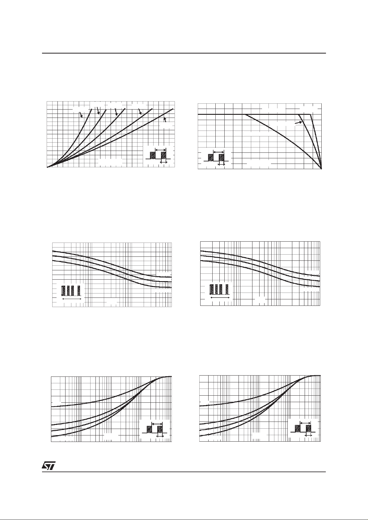
Fig. 1:
Average forward power dissipation versus
averageforwardcurrent(per diode).
PF(av)(W)
8
7
6
5
4
3
2
1
0
0123456789101112
Fig.3-1:
Nonrepetitivesurgepeak forwardcurrent
versus overload duration (maximum values, per
diode)(TO-220ABandD
IM(A)
140
120
100
80
60
40
IM
20
0
1E-3 1E-2 1E-1 1E+0
δ=0.5
t
δ = 0.05
δ = 0.1
δ = 0.2
IF(av)(A)
2
PAK).
t(s)
δ= 0.5
δ
=tp/T
δ =1
T
tp
Tc=75°C
Tc=100°C
Tc=125°C
Fig. 2:
Average current versus ambient
temperature(δ=0.5,perdiode).
IF(av)(A)
12
10
Rth(j-a)=Rth(j-c)
8
6
4
T
2
=tp/T
δ
0
0 25 50 75 100 125 150 175
Fig.3-2:
tp
Nonrepetitivesurgepeak forwardcurrent
Rth(j-a)=15°C/W
Tamb(°C)
ISOWATT220AB
TO-220AB
D PAK
versus overload duration (maximum values, per
diode)(ISOWATT220AB).
IM(A)
100
80
60
40
IM
20
0
1E-3 1E-2 1E-1 1E+0
δ=0.5
t
t(s)
Tc=75°C
Tc=100°C
Tc=125°C
Fig. 4-1:
impedancejunction to case versus pulse duration
(TO-220ABandD
Relative variation of thermal transient
2
PAK).
Zth(j-c)/Rth(j-c)
1.0
0.8
δ= 0.5
0.6
0.4
δ = 0.2
0.2
δ = 0.1
Single pulse
0.0
1E-4 1E-3 1E-2 1E-1 1E+0
tp(s)
T
=tp/T tp
δ
Fig. 4-2:
Relative variation of thermal transient
impedancejunction to case versus pulse duration
(ISOWATT220AB).
Zth(j-c)/Rth(j-c)
1.0
0.8
δ = 0.5
0.6
0.4
δ= 0.2
0.2
δ = 0.1
Single pulse
0.0
1E-3 1E-2 1E-1 1E+0 1E+1
tp(s)
δ
=tp/T
T
tp
3/7
 Loading...