

SGS Thomson Microelectronics STPS10L40CT, STPS10L40CG, STPS10L40CF Datasheet
STPS10L40CT/CG/CF
LOW DROP POWER SCHOTTKY RECTIFIER
MAINPRODUCTSCHARACTERISTICS
I
F(AV)
V
RRM
2x5A
40 V
Tj (max) 150°C
(max) 0.46 V
V
F
FEATURESAND BENEFITS
LOW FORWARD VOLTAGE DROP MEANING
VERYSMALLCONDUCTIONLOSSES
LOW DYNAMIC LOSSES AS A RESULT OF
THESCHOTTKYBARRIER
AVALANCHERATED
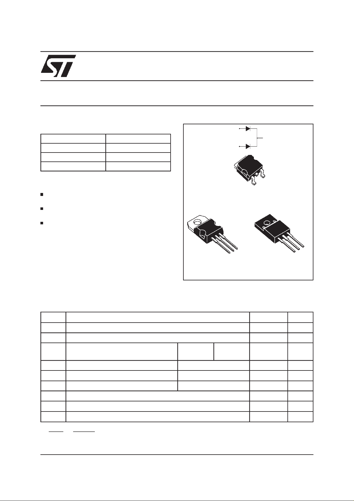
DESCRIPTION
Dual center tap Schottky rectifiers suited for
Switched Mode Power Supplies and high
frequencyDC to DCconverters.
Packaged in TO-220AB, ISOWATT220AB and
2
D
PAK, thesedevicesare intended for use in low
voltage, high frequency inverters, free-wheeling
and polarityprotectionapplications.
A1
TO-220AB
STPS10L40CT
A1
K
A2
K
A2
A1
2
PAK
D
STPS10L40CG
A2
K
ISOWATT220AB
STPS10L40CF
A2
K
A1
ABSOLUTE RATINGS(limiting values,per diode)
Symbol Parameter Value Unit
V
RRM
I
F(RMS)
I
F(AV)
I
FSM
I
RRM
I
RSM
T
stg
Tj
dV/dt
dPtot
*:
dTj
July 1999- Ed:4A
Repetitivepeak reversevoltage
RMSforward current
Averageforwardcurrent Tc= 135°C
Surgenon repetitiveforwardcurrent tp= 10 ms Sinusoidal
Repetitivepeak reversecurrent tp=2µs squareF=1kHz
Nonrepetitive peak reversecurrent tp= 100 µs square
Storagetemperaturerange
Maximumoperating junctiontemperature *
Criticalrate of riseof reverse voltage
<
Rth(j
δ = 0.5
1
thermal runawaycondition for a diodeon its own heatsink
−
a
)
Per diode
Per device
40 V
20 A
5
10
150 A
1A
2A
- 65 to + 150 °C
150 °C
10000 V/µs
A
1/6
STPS10L40CT/CG/CF
THERMAL RESISTANCES
Symbol Parameter Value Unit
R
R
th (j-c)
th (c)
Junctionto case TO-220AB
D
2
PAK
Perdiode
Total
Coupling 0.35
3
1.7
°C/W
R
R
th (j-c)
th (c)
Junctionto case
ISOWATT220AB
Perdiode
Total
3.8
Coupling 2.5
5
°C/W
Whenthe diodes1 and 2 areused simultaneously:
∆ Tj(diode1) = P(diode1)x R
(Per diode)+ P(diode2) x R
th(j-c)
th(c)
STATICELECTRICALCHARACTERISTICS(perdiode)
Symbol Parameter TestsConditions Min. Typ. Max. Unit
*
I
R
V
*
F
Reverseleakage
current
Forwardvoltagedrop Tj= 25°CI
Tj= 25°CV
R=VRRM
Tj= 100°C
=5A
F
Tj= 125°CI
Tj= 25°CI
Tj= 125°CI
=5A
F
=10A
F
=10A
F
825mA
0.36 0.46
0.49 0.59
0.2 mA
0.53 V
0.67
Pulsetest : * tp= 380µs, δ <2%
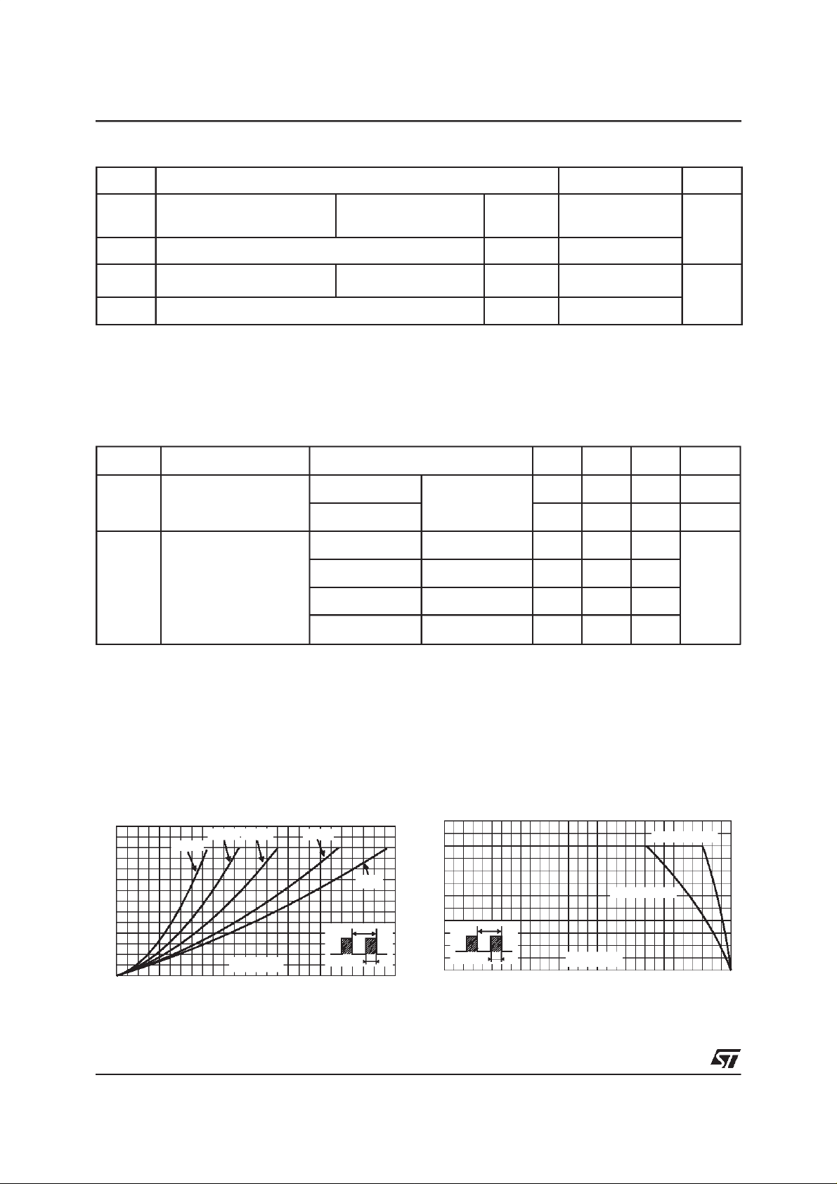
To evaluatethe conductionlossesuse the followingequation :
P = 0.33x I
Fig. 1:
Averageforward power dissipationversus
averageforwardcurrent(per diode).
PF(av)(W)
3.5
3.0
2.5
2.0
1.5
1.0
0.5
0.0
0.0 0.5 1.0 1.5 2.0 2.5 3.0 3.5 4.0 4.5 5.0 5.5 6.0 6.5
2/6
F(AV)
δ= 0.05
+0.026 I
δ = 0.1
δ = 0.2
IF(av) (A)
F2(RMS)
δ = 0.5
δ
=tp/T
δ =1
T
Fig. 2:
temperature(δ=0.5, per diode).
IF(av)(A)
6
5
4
3
2
1
tp
0
0 25 50 75 100 125 150
Average forward current versus ambient
Rth(j-a)=Rth(j-c)
Rth(j-a)=15°C/W
T
δ
=tp/T
tp
Tamb(°C)
 Loading...