

SGS Thomson Microelectronics STM7E1AR, STM7E1A Datasheet
STM7E1A
7 E 1 CHANNELS SWITCH ARRAY
■ MAIN SWITCHES MAX. R
■ PROVIDES 7 AUXILIARY SWITCHES WITH
R
<75Ω
ON
■ 6V
AMPLITUDE OF ANALOG INPUT
PP
LESS THAN 2Ω
ON
SIGNAL
■ DIGITAL INPUTS ARETTL LEVELS
COMPATIBLE
DESCRIPTION
The STM7E1 consists in 7 identical ISDN E1
channels, each channel corresponding to 4 main
low-resistant switches (a and b) and 2 auxiliary
switches (c and d). The switches posi tion s in all
the channels are identical and c ontrolled by a
unique control resource driven by the digital inputs
Lm, Ls and Sc.
In each c hannel, t he TX and RX lines can be
switched bet ween a Main port or a Spare-port by
the main switches: if both "a" switches are closed
and both "b" switches are open, the Main port is
connected to the line, while if both "a" switches
are open and both "b' switches are clo se d, the
spare port is connected to the line.
The 2 auxiliary switches enable to close a local
loop between the TX and RX a ccess of a port: if
"c" is closed, the Spare port RX and TX access is
connected between each other to fo rm a local
loop, while if "d" is closed, the Main port RX and
TX access is connected between each other to
form a local loop.
TQFP64
The Spare port is only used for test purpose on the
system board while the Main port is the
communication channel. Consequently, a
switching from the Main port to the Spare port
occurs very rarely (<10 times a day).
The power sup plies of the chip need to be de
coupled properly. This means that at least one
external capacitor C1 must be connected in
between GND and VPOS, one external c apac it or
C2 between GND and VNE G, and one external
capacitor C3 between each pair of VNEG and
VPOS.
ORDERING CODES
Type
STM7E1A -40 to 85 °C TQFP64 (Tray) 160 parts per Tray
STM7E1AR -40 to 85 °C TQFP64 (Tape & Reel) 1000 parts per reel
Temperature
Range
Package Comments
1/10December 2002
STM7E1A
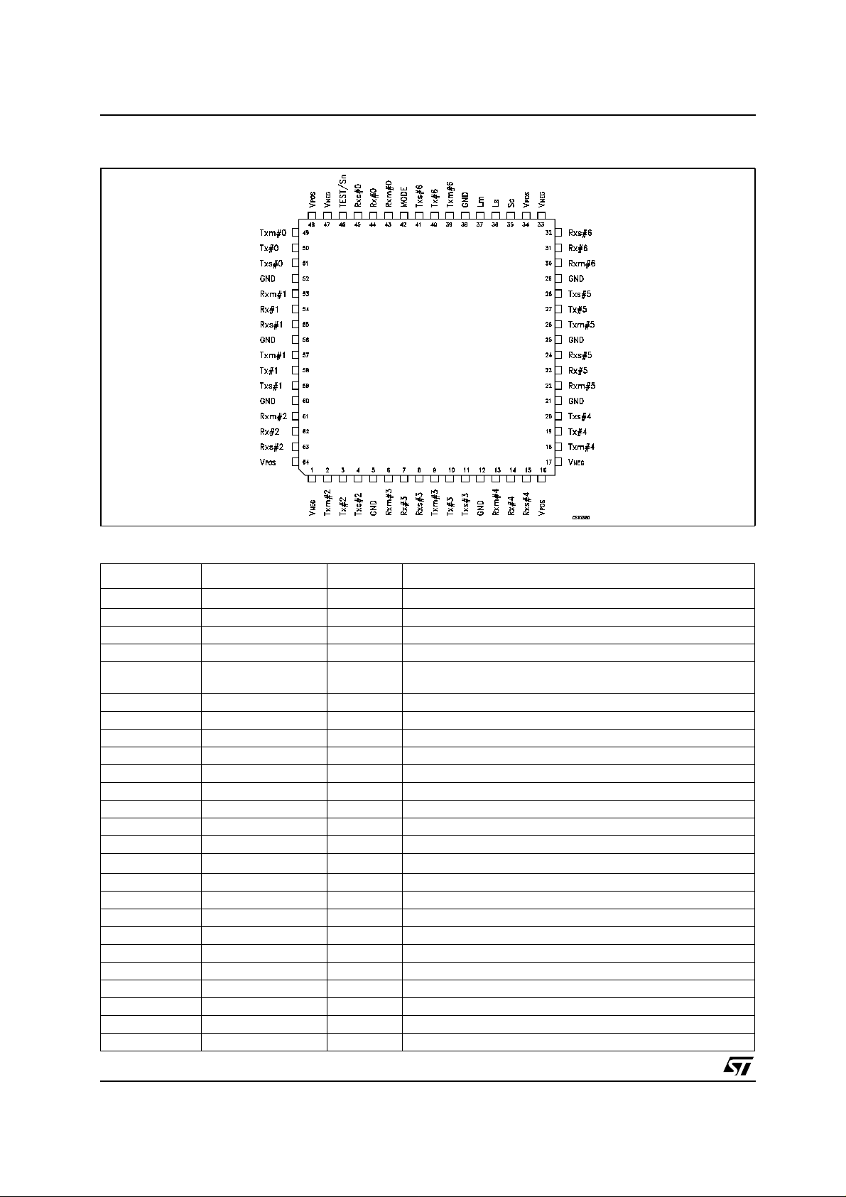
PIN CONFIGURATION
PIN DESCRIPTION
PlN N° SYMBOL TYPE NAME AND FUNCTION
1, 17, 33, 47 V
2 Txm#2 IOA Channel 2: TX main port
3 Tx#2 IOA Channel 2: TX line
4 Txs#2 IOA Channel 2: TX spare port
5, 12, 21, 25, 29,
38, 52, 56, 60
6 Rxm#3 IOA Channel 3: RX main port
7 Rx#3 IOA Channel 3: RX line
8 Rxs#3 IOA Channel 3: RX spare port
9 Txm#3 IOA Channel 3: TX main port
10 Tx#3 IOA Channel 3: TX line
11 Txs#3 IOA Channel 3: TX spare port
13 Rxm#4 IOA Channel 4: RX main port
14 Rx#4 IOA Channel 4: RX line
15 Rxs#4 IOA Channel 4: RX spare port
16, 34, 48, 64
18 Txm#4 IOA Channel 4: TX main port
19 Tx#4 IOA Channel 4: TX line
20 Txs#4 IOA Channel 4: TX spare port
22 Rxm#5 IOA Channel 5: RX main port
23 Rx#5 IOA Channel 5: RX line
24 Rxs#5 IOA Channel 5: RX spare port
26 Txm#5 IOA Channel 5: TX main port
27 Tx#5 IOA Channel 5: TX line
28 Txs#5 IOA Channel 5: TX spare port
30 Rxm#6 IOA Channel 6: RX main port
(1)
NEG
GND G
V
(2)
POS
P
P
Negative Power Supply
Voltage Reference for digital inputs
Positive Power Supply
2/10
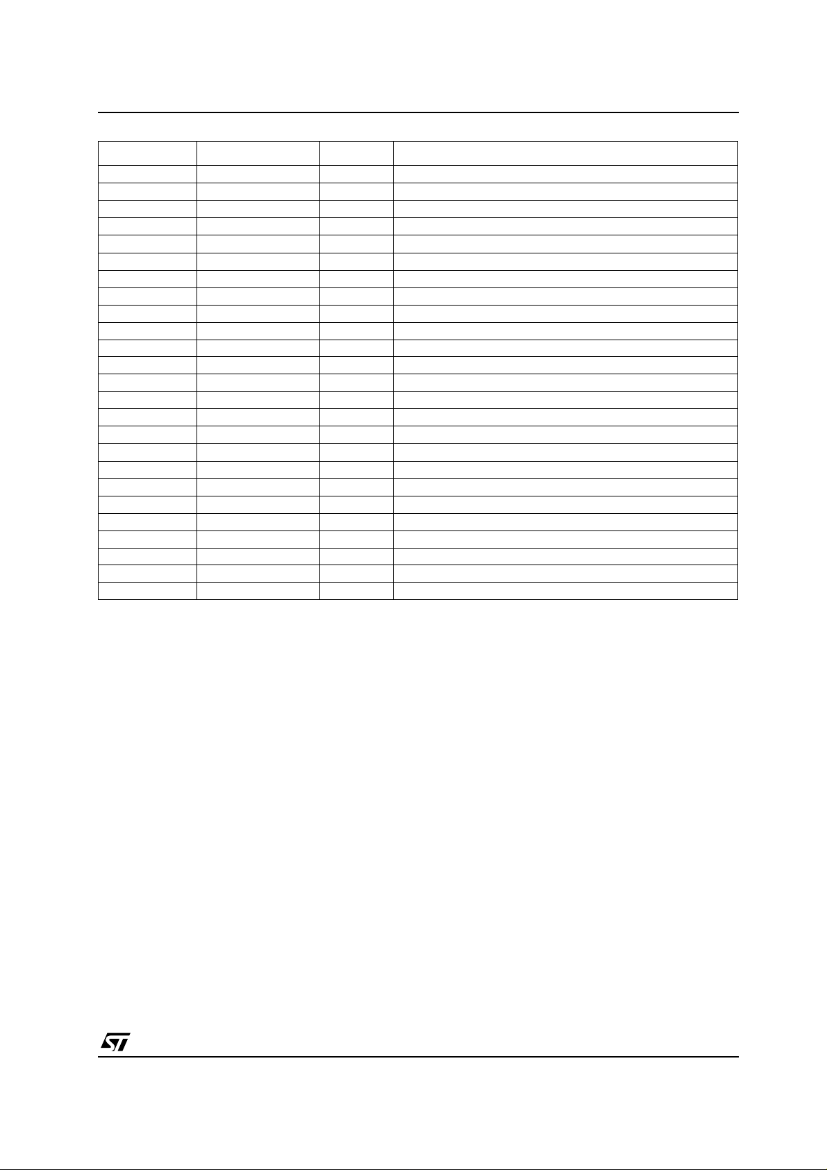
PlN N° SYMBOL TYPE NAME AND FUNCTION
31 Rx#6 IOA Channel 6: RX line
32 Rxs#6 IOA Channel 6: RX spare port
35 Sc I Control digital input
36 Ls I Control digital input
37 Lm I Control digital input
39 Txm#6 IOA Channel 6: TX main port
40 Tx#6 IOA Channel 6: TX line
41 Txs#6 IOA Channel 6: TX spare port
42 Mode I Control Digital Input
43 Rxm#0 IOA Channel 0: RX main port
44 Rx#0 IOA Channel 0: RX line
45 Rxs#0 IOA Channel 0: RX spare port
46 TEST/Sn I Channel 6: RX main port
49 Txm#0 IOA Channel 0: TX main port
50 Tx#0 IOA Channel 0: TX line
51 Txs#0 IOA Channel 0: TX spare port
53 Rxm#1 IOA Channel 1: RX main port
54 Rx#1 IOA Channel 1: RX line
55 Rxs#1 IOA Channel 1: RX spare port
57 Txm#1 IOA Channel 1: TX main port
58 Tx#1 IOA Channel 1: TX line
59 Txs#1 IOA Channel 1: TX spare port
61 Rxm#2 IOA Channel 2: RX main port
62 Rx#2 IOA Channel 2: RX line
63 Rxs#2 IOA Channel 2: RX spare port
NOTE 1: All VNEG pins to be connected together on board.
NOTE 2: All VPOS pins to be connected together on board.
STM7E1A
3/10
 Loading...