

February 2000 1/4
ST7MDTx-EMU2B
REAL-TIME DEVELOPMENT TOOLS
FOR THE ST7 MCU FAMILY
FEATURES
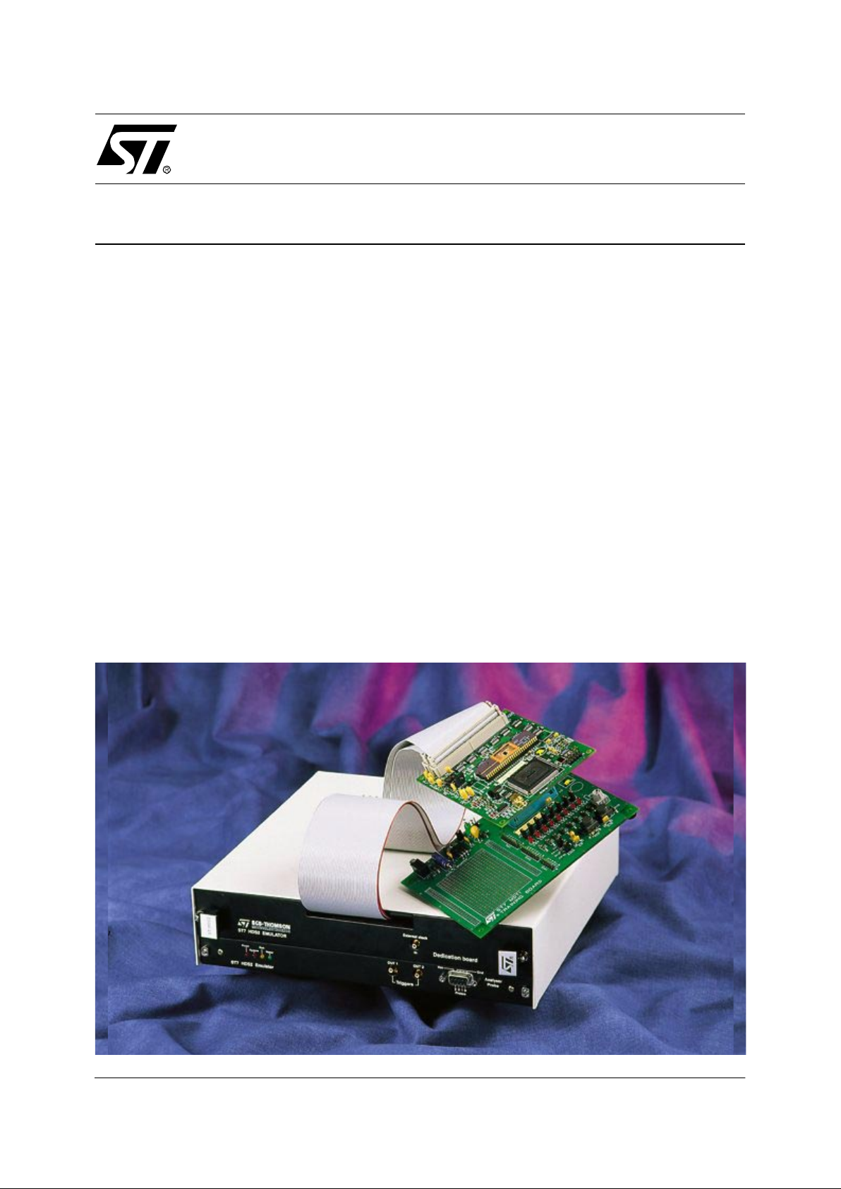
■ A common Hardware Development System
mainframe supports the entire ST7 family of
MCUs, in conjunction with the appropriate
ST7xxx-DBE Active Probe.
■ Real-time source level emulation allows viewing
and breakpoint setting on high level source
code rather than o n disassembled target code
for optimum user friendliness.
■ 64 KBytes of user modifiable and conf igurable
emulation RAM, allows memory mapp ing of all
ST7 family devices as well as modelling
hypothetical memory configurations.
■ Unlimited breakpoints may be set for any op-
code fetch or any address access, and
conditions may be defined for the generation of
2 external synchronization signals.
■ 1K by 32-bit wide t race memory allows complex
and sequential events to be defined on any
combination of address and data, as well as 3
internal and 5 external logic signals.
■ User defined events may trigger a breakpoint or
simply define data capture parameters, in
accordance with user preferences.
■ Simple connection of the emulator system to the
Host PC via parallel port.
■ Emulation syst em may be driven by a Windows-
based GNU debugger software or DOS
software running on host PC, allowing full
control and monitoring of hardware resources.
■ Multiple windows allow concurrent real-time
display of source code, MCU resources, internal
registers, trace data, etc.
■ Log files allow storage and subsequent
redisplay of any displayed screen for
subsequent analysis.
■ Command files can be used to execute a set of
debugger commands in batch mode.
■ Editable configuration files ensure tailoring of
working environment to user preferences.
■ Special Function Register window - symbolic
display of SFR
.
123

2/4
ST7MDTx-EMU2B
OVERVIEW
The ST7 real-time development tools consist of
various hardware and software components,
which together form a flexible and sophisticated
system designed to provide comprehensive development support for the ST7 family of MCUs.
The Hardware Development System (HDS) mainframe is common to all ST7 devices and, in conjunction with various active probes, allows em ulation and development of specific devices. Only the
probe needs to be changed to emulate a new ST7
family device.
The development system is controlled by a Host
PC on which a choice of Windows-based software
may be run. The Host PC is simply c onnected to
the Emulator Mainframe by means of a parallel
port. The STVD7 Windows Debugger software
suite is supplied as standard issue with the Emulator hardware, in addition to the conventional
DOS ST7 Software suite, which includes a macroassembler, a linker/loader. Third party C Toolchain and Debugger software is also available.
The Windows-based debugger provides a user
friendly and highly flexible interface which may be
configured to precisely match the u ser’s requirements. All emulator settings are accessible via the
control software.
Once assembled, and/or compiled and li nked, the
application software may be downloaded to the
real-time emulation memory, which can be configured, mapped and modified as required by the user. The device probe is then connected to the application target hardware in place of the MCU and
real-time emulation of the target application can
begin, thus allowing sophisticated testing and debugging of both application hardware and software.
User definable breakpoints allow t he MCU to be
halted when the application software accesses
specific addresses, and/or addresses within a selected range, and/or on data fetch cycles. The
user may then read and modify any register and
memory location. An on line assembler/disassembler is also available to ease debugging.
An important fe ature of the ST7 d e ve l opment system is that true source level debugging is possible,
meaning code may be v ie wed at sourc e level an d
breakpoints may be s et on high level c ode, rather
than on disasse mbled target code. This is muc h
more meaningful to the user and ensures a more
convivial and productive development environment.
A separate and concurrent Logic Analyzer function is available. This hardware implemented function features 1KByte of 32-bit wide trace memory
which allows events to be defined f or any combination of address (16 bits) and data (8 bits), as
well as according to the state of 3 internal and 5
external logic signals. Complex and sequential
conditions may be defined, and all bits are maskable. The external sig nals are input from 5 probes
which can be connected to the target hardware.
Trace memory events may be used as breakpoints or simply to trigger data acquisition according to user specified param eters, without halting
the target system. Such a powerfu l tool enables
the user to detect an d trap virtually any pattern,
and thus rapidly debug the target application.
Log files offer the ability to send any screen display to a text file. In pa rticular, log files are very
useful to save t he contents of the logic analyzer
and/or the contents of data registers to be subsequently analysed or printed.
Command files can be used to execute a set of
debugger commands in batch mode, to simplify
and speed up the emulation session.
The SFR window offers symbolic display of the
SFRs, showing the peripherals, sym bolic display
of the registers.
Finally, when the target program is fully debugged, the appropriate ST7 EPROM/OTP/
FLASH prog ramming board can be us ed to program the EPROM /OTP/FLAS H version of the target device to allow stand-alone testing and evaluation.
123

3/4
ST7MDTx-EMU2B
ORDERING INFORMATION
Please note that the customer can order either the
whole system with the Emulator or only the Active
probe, if he already has the HDS2 mainframe
DEVICE PACKAGE EMULATOR Active Probe
ST72C104 SDIP32/SO28 ST7MDT1-EMU2B ST7MDT1-DBE2B
ST72C215/C216 SDIP32/SO28 ST7MDT1-EMU2B ST7MDT1-DBE2B
ST72C254 SDIP32/SO28 ST7MDT1-EMU2B ST7MDT1-DBE2B
ST72C124 SDIP42/TQFP44 ST7MDT2-EMU2B ST7MDT2-DBE2B
ST72C334 SDIP42/TQFP44/SDIP56/TQFP64 ST7MDT2-EMU2B ST7MDT2-DBE2B
ST72E5XX/T5XX/E311R/T311R TQFP64 ST7MDT2-EMU2B ST7MDT2-DBE2B
ST72141K2 SDIP32/SO34 ST7MDT5-EMU2B ST7MDT5-DBE2B
ST72171K2 SDIP32/SO34 ST7MDT6-EMU2B ST7MDT6-DBE2B
ST72411R TQFP64 ST7MDT7-EMU2B ST7MDT7-DBE2B
123

4/4
ST7MDTx-EMU2B
Notes:
Information furnished is believed to be accurate and reliable. However, STMicroelectronics assumes no responsibility for the consequences
of use of such information nor for any infringement of patents or other rights of third parties which may result from its use. No license is granted
by implic ation or otherwise under any patent or patent ri ghts of STMicroelectronics . S pecificat i ons menti oned in thi s publication are subject
to change without notice. This publication supersedes and replaces all information previously supplied. STMicroelectronics products are not
authorized for use as cri tical comp onents in lif e support dev i ces or systems wi thout the e xpress written approv al of STMicroel e ctronics.
The ST logo is a registered trademark of STMicroelectronics
2000 STMicroelectronics - All Rights Reserved.
Printed in F rance by Impr i merie AGL
Purchase of I
2
C Components by STMicroelectronics conveys a license under the Philips I2C Patent. Rights to use the se compone nt s i n an
I
2
C system i s granted pro vi ded that the system con forms to the I2C Standard Specification as defined by Philips.
STMicroelectronics Grou p of Compan i es
Australia - Brazil - China - Finland - France - Germany - Hong Kong - India - Italy - Japan - Malaysia - Malta - Morocco - Singapor e - Spain
Sweden - Switzerland - United Kingdom - U .S .A.
http://www.st.com
123
 Loading...