

SGS Thomson Microelectronics ST72623F2, ST72622L4, ST72622L2, ST72622K2, ST72622K4 Datasheet
...
Rev. 0.4
January 2000 1/3
This ispreliminary information on anew product in development or undergoing evaluation. Details are subject tochange without notice.
ST7262
LOW SPEED USB 8-BIT MCU WITH 3 ENDPOINTS, FLASH
MEMORY, LVD, WDG, 10-BIT ADC, 2 TIMERS, SCI, SPI
DATA BRIEFING
■ 8K or 16K Program memory
(ROM, FASTROM or Dual voltage FLASH)
with read-write protection
■ 384 to 768 bytes RAM memory (128 bytes
stack)
■ In-Situ Programming for FLASH versions
■ Enhanced Reset System (Power On Reset)
■ Low Voltage Detector (LVD)
■ 3 Power saving modes
■ USB (Universal Serial Bus) Interface with DMA
for low speed applications compliant with USB
1.5 Mbs specification (v 1.1) and USB HID
specification (v 1.0):
– Integrated 3.3V voltage regulator and trans-
ceivers
– Suspend and Resume operations
– 3 Endpoints
■ Up to 31 multifunctional bidirectional I/O lines
with:
– Up to 12 External interrupts (2 vectors)
– 13 alternate function lines
– 8 high sink outputs (8mA@0.4 V/20mA@1.3)
– 2 true open drain pins (N buffer 8mA@0.4 V)
■ Clock-out capability
■ Configurable watchdog reset (8 to 500ms
timeout)
■ Two cascadable 8-bit timers:
– Auto Reload Timer with 2 Input Captures, 2
PWM outputs and External Clock Input
– Time Base Unit (TBU) for generating periodic
interrupts.
■ Asynchronous Serial Communication interface
■ Synchronous Serial Peripheral Interface
■ 10-bit A/D Converter with up to8 input pins.
■ 8-bit data manipulation
■ 63 basic instructions
■ 17 main addressing modes
■ 8 x 8 unsigned multiply instruction
■ True bit manipulation
■ Full hardware/software development package
Device Summary
PDIP32 shrinkSO34 shrink
TQFP44 PDIP42 shrink
SO20 PDIP20
Features ST72623F2 ST72622K2 ST72622K4 ST72622L2 ST72622L4 ST72621J4
Program memory - bytes 8K 8K 16K 8K 16K 16K
RAM (stack) - bytes 384 (128) 384 (128) 512 (128) 384 (128) 512 (128) 768 (128)
Peripherals USB, Watchdog, Low Voltage Detector, 8-bit Auto-Reload timer, Timebase unit, A/D Converter
Serial I/O - SPI SPI SPI SPI SPI + SCI
I/Os 11
21
21 23 23 31
Operating Supply 4.0V to 5.5V
Oscillator Frequency 6 or 12 MHz
Operating Temperature 0°C to +70°C
Packages PDIP20/SO20 PDIP32 SO34 PDIP42/TQFP44
1
ST7262
2/3
1 GENERAL DESCRIPTION
1.1 INTRODUCTION
The ST7262, ST72P62 and ST72F62 devices are
members of the ST7 microcontroller family designed for USB applications.
All devices are based on a common industrystandard 8-bit core, featuringan enhanced instruction set.
The ST7262 ROM and ST72P62 FASTROM devices are factory-programmed and are not reprogrammable.
The ST72F62 versions feature dual-voltage
FLASH memory with In-Situ Programming (ISP)
capability.
Under software control, all devices can be placed
in WAIT, SLOW, or HALT mode, reducing power
consumption when the application is in idle or
standby state.
The enhanced instruction set and addressing
modes of the ST7 offer both power and flexibilityto
software developers, enabling the design ofhighly
efficient andcompact application code. In addition
to standard 8-bit data management, all ST7 microcontrollers feature true bit manipulation, 8x8 unsigned multiplication and indirect addressing
modes.
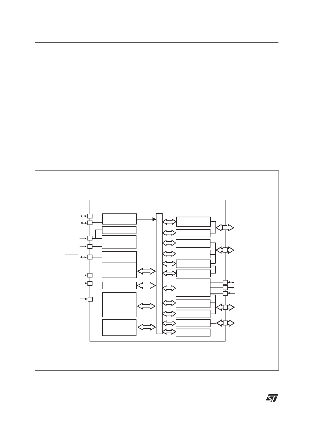
Figure 1. General Block Diagram
8-BIT CORE
ALU
ADDRESS AND DATA BUS
OSCIN
OSCOUT
RESET
PORT B
USB SIE
PORT A
SCI
PORT C
SPI
PB7:0
(8 bits)
PC7:0
(8 bits)
OSCILLATOR
Internal
CLOCK
CONTROL
RAM
(384, 512
PA7:0
(8 bits)
V
SS
V
DD
POWER
SUPPLY
PROGRAM
(8 or 16K Bytes)
LVD
10-BIT ADC
MEMORY
WATCHDOG
USBDP
USBDM
USBVCC
PWM ART
USB DMA
V
SSA
V
DDA
PORT D
PD6:0
(7 bits)
TIME BASE UNIT
V
PP
or 768 Bytes)
2
 Loading...