

SGS Thomson Microelectronics ST6203LM1, ST6203LB1, ST6203L, ST6201LM1, ST6201LB1 Datasheet
...
R
LOW VOLTAGE 8-BIT ROM MCUs WITH
■
2.4 to 3.9V Supply Operating Range
■ 4 MHz Maximum Clock Frequency
■
0to+70°C Operating Temperature Range
■
Run, Wait and Stop Modes
■
5 Interrupt Vectors
■ Look-up Table capability in Program Memory
■
Data Storage in Program Memory:
User selectable size
■
Data RAM: 64bytes
■ 9 I/O pins, fully programmable as:
– Input with pull-up resistor
– Input without pull-up resistor
– Input with interrupt generation
– Open-drain or push-pull output
– Analog Input (except ST6203L)
■
3 I/O lines can sink up to 12mA to drive LEDs
■
8-bit Timer/Counter with 7-bit programmable
prescaler
■ Digital Watchdog
■
8-bit A/D Converter with up to 4 analog inputs
■
On-chip Clock oscillatorcan be driven byQuartz
Crystal Ceramic resonator or RC network
■ Power-on Reset
■
One external Non-Maskable Interrupt
■
ST626x-EMU2 Emulation and Development
System (connects to an MS-DOS PC via an
RS232 serial line)
ST6200L/01L/03L
A/D CONVERTER,AND 16 PINS
PDIP16
PSO16
(See end of Datasheet for Ordering Information)
DEVICE SUMMARY
DEVICE
ST6200L 1036 9 4
ST6201L 1836 9 4
ST6203L 1036 9 None
ROM
(Bytes)
I/O Pins
Analog
inputs
Rev. 1.0
November 1997 1/10
1
ST6200L/01L/03L
1 GENERAL DESCRIPTION
1.1 INTRODUCTION
The ST6200L/01L and 03L are low voltage mask
programmed ROM version of ST62T00C,T01C
and T03C OTP devices.
They offer the same functionality as OTP devices,
selecting as ROM options the options defined in
the programmable option byte of the OTP version,
with the exception of the LVD Reset and the OSG
that are not available.
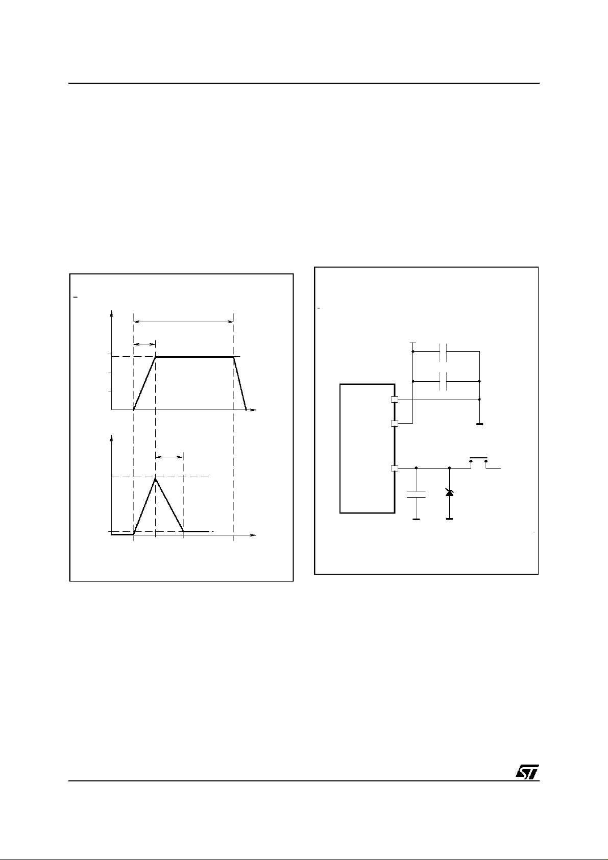
Figure 1. Programming wave form
TEST
100 s max
15
14V typ
10
5
TEST
0.5s min
150 s typ
t
1.2 ROM READOUT PROTECTION
If the ROM READOUT PROTECTION option is
selected, a protection fuse can be blown to prevent any access to the program memory content.
In case the user wants to blow this fuse, high voltage must be applied on the TEST pin.
Figure 2. Programming Circuit
5V
47 F
m
100nF
V
SS
V
DD
PROTECT
100mA
max
4mA typ
t
VR02001
TEST
100nF
ZPD15
15V
14V
VR02003
Note: ZPD15 is used for overvoltage protection
2/10
1

ST6200L/01L/03L
ST6200L/01L/03L MICROCONTROLLER OPTION LIST
Customer . . . ..........................
Address .............................
.............................
Contact . . . ..........................
PhoneNo .............................
Reference . . . ..........................
SGS-THOMSON Microelectronics references
Device: [ ] ST6200L [ ] ST6201L [ ] ST6203L
Package: [ ] Dual in Line Plastic[ ] Small Outline Plastic with conditionning:
[ ] Standard (Stick)
[ ] Tape & Reel
Temperature Range: [ ] 0°Cto+70°C
Special Marking: [ ] No [ ] Yes ”_ _ _ _ _ _ _ _ _ _ _ ”
Authorized characters are letters, digits, ’.’, ’-’, ’/’ and spaces only.
Maximum character count: DIP16: 9
SO16: 6
Oscillator Source Selection: [ ] Crystal Quartz/Ceramic resonator
[ ] RC Network
Watchdog Selection: [ ] Software Activation
[ ] Hardware Activation
ROM Readout Protection: [ ] Disabled (Fuse cannot be blown)
[ ] Enabled (Fuse can be blown by the customer)
Note: No part is delivered with protected ROM.
The fuse must be blown for protection to be effective.
External STOP Mode Control[ ] Enabled [ ] Disabled
NMI pin pull-up [ ] Enabled [ ] Disabled
Comments :
Supply Operating Range in the application:
Oscillator Fequency in the application:
Notes . . . ..........................
Signature . . . ..........................
Date .............................
3/10
1
 Loading...