

Datasheet SMP100-270, SMP100-65, SMP100-8, SMP100LC-35, SMP100-120 Datasheet (SGS Thomson Microelectronics)
...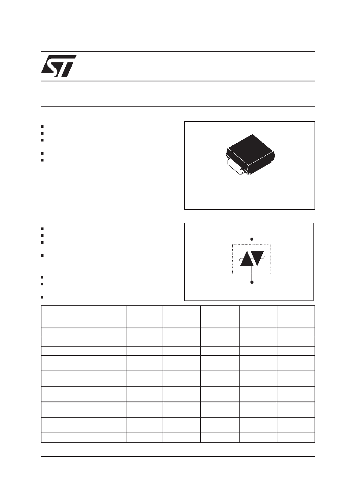
SMP100-xxx
COMMUNICATIONEQUIPMENT PROTECTION: TRISIL
FEATURES
BIDIRECTIONALCROWBARPROTECTION
VOLTAGERANGE: FROM 8V to 270V
REPETITIVEPEAK PULSECURRENT:
= 100 A (10/1000µs)
I
PP
HOLDINGCURRENT: I
LOWLEAKAGECURRENT:I
DESCRIPTION
The SMP100 series are transient surge arrestorsusedfortheprotection of sensitive telecomequipment.
MAINAPPLICATIONS
Any sensitive equipment requiring protection
againstlightningstrikes :
ANALOGAND DIGITALLINE CARDS
MAINDISTRIBUTIONFRAMES
TERMINALSAND TRANSMISSION
EQUIPMENT
GAS-TUBEREPLACEMENT
BENEFITS
= 150mAor 225mA
H
=2µA max
R
SMB
(JEDECDO-214AA)
SCHEMATICDIAGRAM
TM
NOAGEINGAND NO NOISE
IF DESTROYED, THE SMP100 FALLS INTO
SHORTCIRCUIT,STILLENSURINGPROTECTION
BOARDSPACESAVING
COMPLIESWITHTHE
FOLLOWINGSTANDARDS:
ITUK20 4000 10/700 5/310 100 VDE0433 4000 10/700 5/310 100 VDE0878
IEC-1000-4-5
FCCPart 68, lightning surge
type A
FCCPart 68, lightning surge
type B
BELLCORETR-NWT-001089
Firstlevel
BELLCORETR-NWT-001089
Secondlevel
CNETl31-24 4000 0.5/700 0.8/310 100 -
Peak Surge
Voltage
(V)
4000 1.2/50 1/20 100 -
level4
level4
1500
800
100 9/720 5/320 25 -
2500
1000
5000 2/10 2/10 500 -
Voltage
Waveform
(µs)
10/700
1.2/50
10/160
10/560
2/10
10/1000
Current
Waveform
(µs)
5/310
8/20
10/160
10/560
2/10
10/1000
Admissible
Ipp
(A)
100
100
200
100
500
100
Necessary
Resistor
(Ω)
-
-
-
-
-
-
August 1999-Ed : 8A
1/9
SMP100-xxx
THERMAL RESISTANCES
Symbol Parameter Value Unit
R
R
th(j-I)
th(j-a)
Junctionto leads 20 °C/W
Junctionto ambienton printedcircuit
100 °C/W
(withstandardfootprint dimensions)
ABSOLUTE MAXIMUMRATINGS
(T
amb
=
25°C)
Symbol Parameter Value Unit
I
pp
I
FS
I
TSM
T
L
T
stg
Tj
Peakpulse current:
10/1000µs (open circuitvoltagewaveform1 kV 10/1000µs)
5/310µs (opencircuitvoltage waveform4 kV, 10/700µs)
8/20µs (open circuit voltagewaveform4 kV 1.2/50 µs)
2/10µs (opencircuitvoltage waveform2.5kV 2/10 µs)
100
150
250
500
Fail-safemode 8/20 µs5kA
Nonrepetitivesurge peak on-statecurrent
Onecycle
Nonrepetitivesurge peak on-statecurrent
F= 50Hz
50Hz
60Hz
0.2s
2s
55
60
25
12
Maximumlead temperaturefor solderingduring 10s 260 °C
Storagetemperaturerange
Maximumjunction temperature
- 55 to+ 150
150
A
A
A
A
A
A
A
A
°C
°C
Note1:
2/9
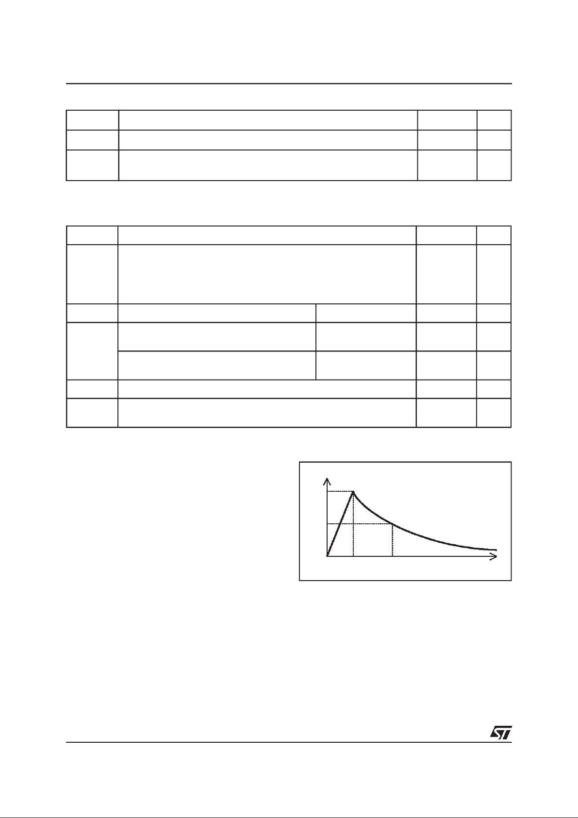
Pulsewaveform
10 / 1000µstr=10µs tp = 1000
µs
8/20µstr=8µstp=20µs
5 / 310µstr=5
1/20µstr=1
µ
s tp = 310µs
µ
stp=20
µ
s
2/10µstr=2µstp=10µs
100
50
0
%I
PP
t
r
t
p
t
SMP100-xxx
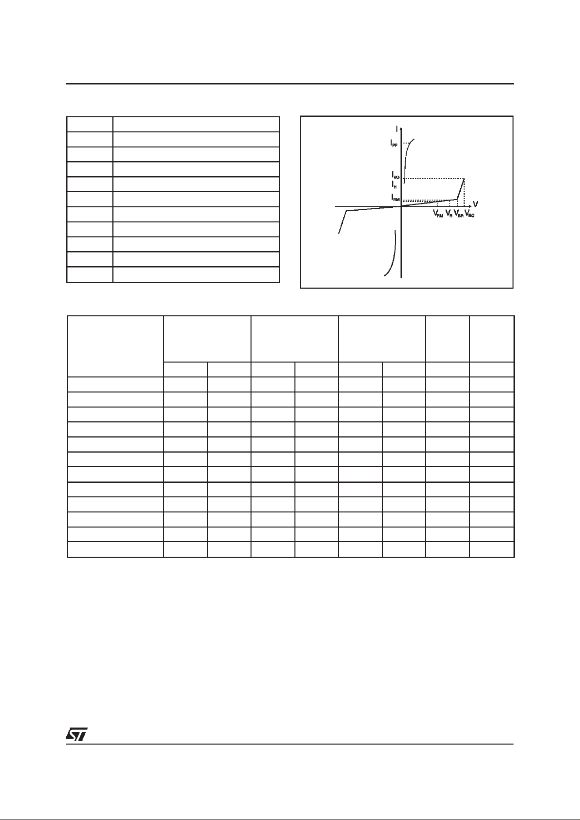
ELECTRICALCHARACTERISTICS(T
amb
=25°C)
Symbol Parameter
V
RM
I
RM
V
R
I
R
V
BR
V
BO
I
H
I
BO
I
PP
C
Stand-offvoltage
Leakagecurrent at stand-offvoltage
Continuousreversevoltage
Continuousreversecurrent
Breakdownvoltage
Breakovervoltage
Holdingcurrent
Breakovercurrent
Peak pulse current
Capacitance
STATICPARAMETERS
Type
@V
I
RM
RM
max.
AV
µ
I
@V
R
R
max.
note 1
AV VmAmApF
µ
V
BO
max.
note 2
@I
BO
I
H
min.
note 3
SMP100-8 2 6 50 8 20 800 50(typ) 100
SMP100LC-35 2 32 50 35 55 800 150 90
SMP100-65 2 55 50 65 80 800 150 160
SMP100-120 2 110 50 120 160 800 150 140
SMP100-140 2 120 50 140 200 800 150 140
SMP100-200 2 170 50 200 265 800 150 130
SMP100-230 2 200 50 230 300 800 150 120
SMP100-270 2 230 50 270 350 800 150 120
SMP100-140H225 2 120 50 140 200 800 225 140
SMP100-200H225 2 170 50 200 265 800 225 130
SMP100-230H225 2 200 50 230 300 800 225 130
SMP100-270H225 2 230 50 270 350 800 225 120
Note 1 : IRmeasured at VRguaranteesVBR>V
Note 2 : Measuredat 50Hz, see testcircuit1. In any caseV
Note 3 : See functional holdingcurrent test circuit 2.
Note 4 : VR=1Vbias, V
=1V,F=1MHz.
RMS
R
BOmin
≥ V
BR
C
typ.
note 4
3/9

SMP100-xxx
DYNAMICPARAMETERS
Symbol Test conditions(see note 5) Type Max. Unit
SMP100-8 25
SMP100LC-35 55
SMP100-65 95
SMP100-120 200
Testconditions1
dV/dt= 100 V/µs, di/dt< 10 A/µs,I
V
BO
= 100A
PP
Testconditions2
dV/dt= 1kV/µs, di/dt < 10A/µs, I
Note 5 : VBOparameters are given by a KeyTek ’System2’ generator with PN246I module.
Seetest circuits 3 forVBOdynamic parameters.
PP
=10A
SMP100-140 220
SMP100-200 285
SMP100-230 320
SMP100-270 370
SMP100-140H225 220
SMP100-200H225 285
SMP100-230H225 320
SMP100-270H225 370
V
TESTCIRCUIT1 FOR I
Transformer
TESTPROCEDURE:
PulseTest duration (tp = 20ms):
-For Bidirectionaldevices= Switch K is closed
-For Unidirectionaldevices = Switch K is open.
V
Selection
OUT
-Device with V
-V
- Devicewith V
-V
andVBOparameters:
BO
Auto
220V/2A
220V
Transformer
220V/800 V
5A
<
200 Volt
BO
= 250 V
OUT
OUT
BO
= 480V
RMS,R1
≥ 200 Volt
RMS,R2
static
relay.
V
out
=140Ω.
=240 Ω.
=20ms
tp
K
I
BO
measure
R1
140
R2
240
D.U.T
V
BO
measure
4/9

SMP100-xxx
TESTCIRCUIT2 for IHparameter.
R
-V
P
V
BAT
D.U.T.
= - 48 V
Surge generator
This is a GO-NOGO testwhich allows to confirmthe holdingcurrent (IH)level in a functionaltest circuit.
TESTPROCEDURE:
- Adjust the currentlevel at the I
- Firethe D.U.T. witha surgecurrent: I
- TheD.U.T. will comeback to the off-statewithin 50 ms max.
value by short circuiting the D.U.T.
H
=10A, 10/1000µs.
pp
TESTCIRCUITS3 FORVBODYNAMICPARAMETERS
100 V / µs, di/dt < 10 A / µs, Ipp = 100 A
2 Ω
U
KeyTek’System 2’ generator with PN246I module
10 µF
1kV/µs, di/dt < 10 A / µs, Ipp = 10 A
26 µH
U
KeyTek’System 2’ generator with PN246I module
60 µF
12 Ω
250 Ω
45 Ω
47 Ω
66 Ω
470 Ω
46 µH
83 Ω
0.36 nF
46 µH
5/9

SMP100-xxx
TYPICALAPPLICATIONS
1 - Primary protectionmodule
3 * SMP100
MDF
2 - Line card protection
Line
Card
-V
bat
LINE A
LINE B
PTC
PTC
3 * SMP100
3 - ISDN: U interfaceprotection
PTC
PTC
3 * SMP100
RING
RELAY
R3
R4
R5
R6
LCP1511D
1/2 DA108S1
+5V
R
Integrated
SLIC
220
nF
R
Internal
circuitry
6/9
Feeder

SMP100-xxx
Fig 1 :
versusoverloadduration(T
70
60
50
40
30
20
10
Fig 3 :
Non repetitivesurge peak on-state current
initial= 25 °C).
j
I (A)TSM
F=50Hz
0
1E-2 1E-1 1E+0 1E+1 1E+2 1E+3
t(s)
Relativevariation of holding currentversus
junctiontemperature.
IH[Tj] / IH[Tj=25°C]
2.0
1.8
1.6
1.4
1.2
1.0
0.8
0.6
0.4
0.2
0.0
-40 -20 0 20 40 60 80 100 120
T(°C)j
Fig 2 :
On-state voltage versus on-state current
(typicalvalues).
I (A)
T
50
Tj=25°C
10
1
2.0 2.2 2.4 2.6 2.8 3.0 3.2 3.4 3.6 3.8 4.0
Fig 4 :
Variation of thermal impedancejunction to
V (V)T
ambientversuspulse duration.
Zth(j-a)(°CW)
100
10
1
1E-3 1E-2 1E-1 1E+0 1E+1 1E+2 5E+2
t (s)p
Fig 5 :
Relative variation of junction capacitance
versusreversevoltageapplied (typicalvalues).
Note : For other types than SMP100-8, the curve can be
extrapolated(dotted line)
C[VR]/C[VR=1V]
1.0
F=1MHz
0.5
0.2
0.1
1 10 100 500
V (V)R
7/9

SMP100-xxx
MARKING
Type Marking Package Weight Baseqty Delivery mode
SMP100-8 PL8 SMB 0.107g 2500 Tape& Reel
SMP100LC-35 L35 SMB 0.107g 2500 Tape& Reel
SMP100-65 P06 SMB 0.107g 2500 Tape& Reel
SMP100-120 P12 SMB 0.107g 2500 Tape& Reel
SMP100-140 P14 SMB 0.107g 2500 Tape& Reel
SMP100-200 P20 SMB 0.107g 2500 Tape& Reel
SMP100-230 P23 SMB 0.107g 2500 Tape& Reel
SMP100-270 P27 SMB 0.107g 2500 Tape& Reel
SMP100-140H125 P16 SMB 0.107g 2500 Tape& Reel
SMP100-200H225 P22 SMB 0.107g 2500 Tape& Reel
SMP100-230H225 P24 SMB 0.107g 2500 Tape& Reel
SMP100-270H225 P29 SMB 0.107g 2500 Tape& Reel
EpoxymeetsUL94, V0
ORDERCODE
SURFACE
MOUNT
PROTECTION
SMP 100
IPP=100A
270 H225
-
VOLTAGE
H225: I
=225mA
H
:I
= 150mA
H
8/9

PACKAGEMECHANICAL DATA
SMB(Plastic)
SMP100-xxx
E1
E
C
L
FOOTPRINT (in millimeters)
DIMENSIONS
REF.
Millimeters Inches
Min. Max. Min. Max.
D
A1 1.90 2.45 0.075 0.096
A2 0.05 0.20 0.002 0.008
b 1.95 2.20 0.077 0.087
c 0.15 0.41 0.006 0.016
A1
A2
b
E 5.10 5.60 0.201 0.220
E1 4.05 4.60 0.159 0.181
D 3.30 3.95 0.130 0.156
L 0.75 1.60 0.030 0.063
2.3
1.52 2.75
Informationfurnishedis believed to be accurateand reliable.However, STMicroelectronicsassumes no responsibility for theconsequences of
use of such information nor forany infringementof patents or otherrights ofthird parties which may result from its use. No license is grantedby
implication or otherwise under any patent or patent rights of STMicroelectronics. Specifications mentioned in this publication are subject to
change without notice. This publicationsupersedes and replacesall informationpreviously supplied.
STMicroelectronics products are not authorized for use as critical components in life support devices or systems without express written
approvalof STMicroelectronics.
1.52
The ST logois a registeredtrademark of STMicroelectronics
1999 STMicroelectronics - Printed in Italy -All rights reserved.
STMicroelectronics GROUP OF COMPANIES
Australia - Brazil - China - Finland - France - Germany - Hong Kong - India - Italy - Japan - Malaysia
Malta - Morocco - Singapore - Spain - Sweden - Switzerland - United Kingdom - U.S.A.
http://www.st.com
9/9
 Loading...