

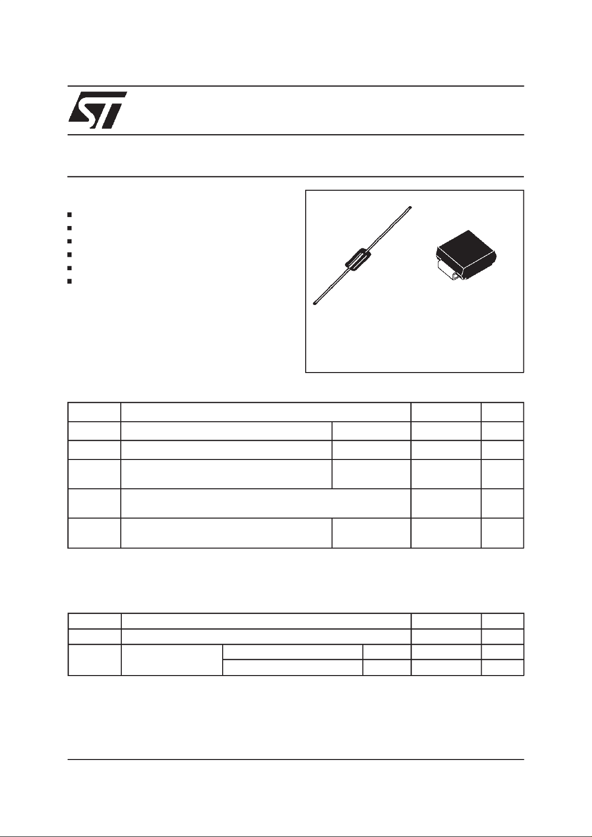
1N5908
SM5908
TRANSIL
FEATURES
UNIDIRECTIONALTRANSILDIODE
PEAKPULSEPOWER: 1500 W (10/1000µs)
REVERSESTANDOFFVOLTAGE: 5V
LOW CLAMPINGFACTOR
FASTRESPONSETIME
UL RECOGNIZED
DESCRIPTION
The1N5908and SM5908are dedicatedtothe5 V
logiccircuitprotecti on(TT LandCMOStechnologi es ).
Their low clamping voltage at high current level
guarantees excellent protection for sensitive
components.
ABSOLUTEMAXIMUMRATINGS (T
amb
=25°C).
Symbol Parameter Value Unit
CB429 SMC
TM
P
PP
P Powerdissipationon infiniteheatsink T
I
FSM
T
stg
Tj
T
L
Note 1 : For a surge greater than themaximum values, the diodewill failin short-circuit.
Peakpulse powerdissipation(see note1) Tj initial = T
=75°C5W
amb
Nonrepetitivesurgepeakforwardcurrent
for unidirectionaltypes
tp=10ms
T
initial= T
j
Storagetemperaturerange
Maximumjunction temperature
Maximumlead temperaturefor soldering
during10s (at 5mm from case for CB429)
CB429
SMC
amb
amb
1500 W
200 A
- 65 to +175
175
230
260
THERMALRESISTANCES
Symbol Parameter Value Unit
R
R
th (j-l)
th (j-a)
Junctionto leads 20 °C/W
Junctionto ambient
on printedcircuit.
L lead= 10 mm
Onrecommendedpadlayout
CB429 75 °C/W
SMC 75 °C/W
°C
°C
°C
°C
August 1999 Ed : 2A
1/6
1N5908/SM5908
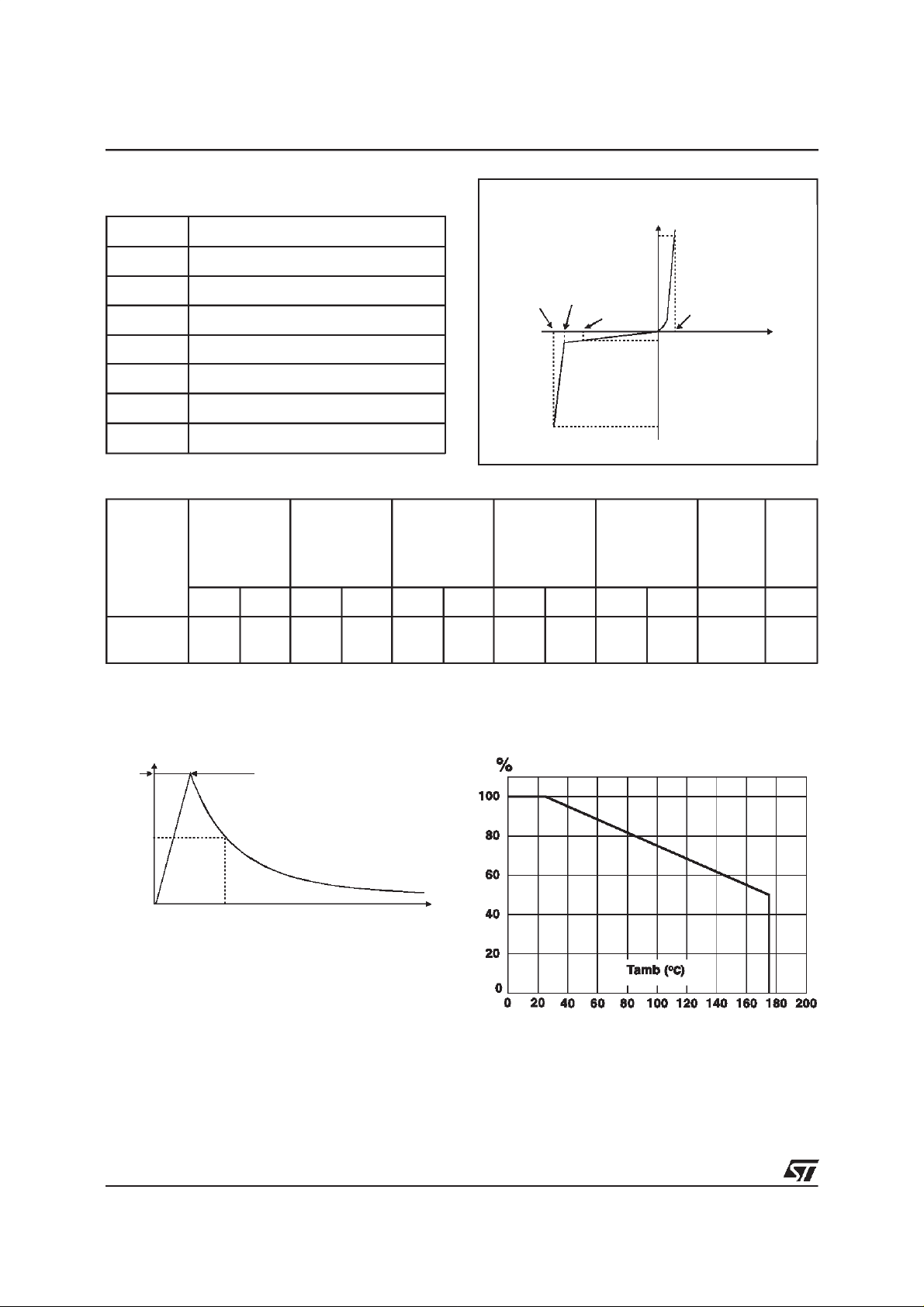
ELECTRICALCHARACTERISTICS(T
Symbol Parameter
V
RM
V
BR
V
CL
I
RM
I
PP
α
T Voltagetemperaturecoefficient
V
F
Types
Stand-offvoltage
Breakdownvoltage
Clampingvoltage
Leakagecurrent @ VRM
Peakpulse current
Forwardvoltage
I
RM
@V
VBR@IRVCL@I
RM
max min max max max max typ
note2 10/1000µs 10/1000µs 10/1000µs note3 note4
µAVVmAVAVAVA10
1N5908
300 5 6 1 7.6 30 8 60 8.5 120 5.7 9500
SM5908
amb
=25°C)
V
BR
V
CL
VCL@IPPVCL@I
PP
I
I
F
V
V
RM
F
V
I
RM
I
PP
PP
αTC
-4
/°CpF
%I
PP
100
10
sµ
50
0
s
µ
1000
Note 2 : Pulse test: tp < 50ms
Note 3 : ∆V
Note 4 :V
2/6
=αT*(T
BR
= 0V,F = 1 MHz
R
-25)* VBR(25°C).
amb
Fig. 1: Peakpulse powerdissipationversus
initial junction temperature (printedcircuitboard).
t

Fig. 2 : Peakpulsepower versusexponentialpulseduration.
1N5908/SM5908
Fig.3 : Clampingvoltage versuspeak pulse current.
Exponentialwaveform t
= 10ms...............
p
= 1ms-------------
t
p
=20µs________
t
p
Note : The curves of thefigure3 are specifiedfora junctiontemperatureof 25 °C before surge.
Thegiven resultsmay beextrapolatedfor otherjunction temperaturesby using the following formula:
∆V
BR
= αT*(T
- 25)*VBR(25°C).
amb
3/6

1N5908/SM5908
Fig. 4 : Capacitance versus reverse applied
voltage (typical values).
Fig. 5 : Peak forward voltage drop versus peak
forward current.
Fig. 6a/6b : Transientthermalimpedancejunction-ambientversus pulseduration.
Fig.6a :
CB429Package.
(ForFR4 PCBoard withL
=10 mm)
lead
Fig.6b :
SMCPackage.
Mounting on FR4 PC Board with recommended
padlayout.
Fig.7 :
Relative variation ofleakagecurrent
versus junction temperature.
4/6

ORDERCODE
1N5908/SM5908
1N5908 RL SM 5908
Devicecode
Packaging:
=Ammopack tape
RL = Tapeand reel
MARKING :Logo, typecodeandcathodeband
Package Type Marking
SMC SM5908 MDC
CB429 1N5908 1N5908
A white band indicates the cathode
PACKAGE MECHANICAL DATA
SMC
(Plastic)
E1
D
E
A1
C
L
E2
A2
b
Numericalcode
Surfacemount
DIMENSIONS
REF.
Millimeters Inches
Min. Max. Min. Max.
A1 1.90 2.45 0.075 0.096
A2 0.05 0.20 0.002 0.008
b 2.90 3.2 0.114 0.126
c 0.15 0.41 0.006 0.016
E 7.75 8.15 0.305 0.321
E1 6.60 7.15 0.260 0.281
E2 4.40 4.70 0.173 0.185
D 5.55 6.25 0.218 0.246
L 0.75 1.60 0.030 0.063
FOOTPRINT (in millimeters)
2.0 4.2 2.0
Packaging
:Standardpackagingis intapeandreel.
3.3
Weight
=0.25 g.
5/6

1N5908/SM5908
PACKAGEMECHANICALDATA
CB429(Plastic)
DIMENSIONS
REF.
Millimeters Inches
Min. Typ. Max. Min. Typ. Max.
A 9.45 9.50 9.80 0.372 0.374 0.386
B 26 1.024
∅ C 4.90 5.00 5.10 0.193 0.197 0.201
∅ D 0.94 1.00 1.06 0.037 0.039 0.042
L1 1.27 0.050
Packaging
:Standardpackagingis intapeandreel.
Weight= 0.85 g.
Note: Theleadisnot controlledwithin zoneL
1
Informationfurnished is believedto be accurate and reliable. However, STMicroelectronics assumes no responsibilityfor the consequences of
use ofsuch information nor forany infringementof patentsor other rights of thirdparties which mayresult fromits use. No license is grantedby
implication or otherwiseunder any patent or patent rights of STMicroelectronics. Specifications mentioned in this publication are subject to
change withoutnotice. This publication supersedes and replacesall information previously supplied.
STMicroelectronics products are not authorized for use as critical components in life support devices or systems without express written approval of STMicroelectronics.
The ST logo is a registered trademark of STMicroelectronics
1999STMicroelectronics - Printed in Italy- All rights reserved.
STMicroelectronics GROUP OF COMPANIES
Australia - Brazil - China - Finland - France - Germany - Hong Kong - India -Italy - Japan - Malaysia
Malta - Morocco - Singapore - Spain -Sweden - Switzerland - United Kingdom - U.S.A.
http://www.st.com
6/6
 Loading...