

.50 MHz
.12.5 VOLTS
.EFFICIENCY 55%
.COMMON EMITTER
.GOLD METALLIZATION
.P
OUT
70 W MIN. WITH 10 dB GAIN
=
SD1446
RF & MICROWAVE TRANSISTORS
HF/VH F APPLICA TIONS
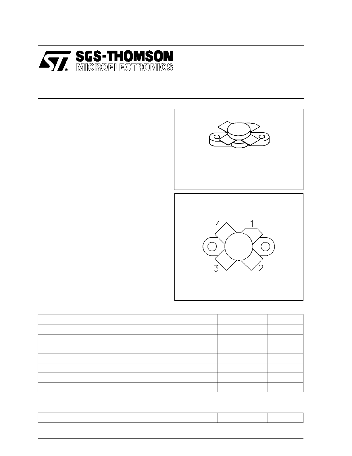
.380 4LF L (M113)
epoxy sealed
ORDER CODE
SD1446
PIN CONNECTION
BRANDING
SD1446
DESC RI PT ION
The SD1446 is a 12.5 V Class C epitaxial silicon
NPN planar transistor designed primarily for land
mobile transmitter applications. Thisdevice utilizes
emitter ballasting and is extremely stable and capable of withstanding high VSWR under operating
conditions.
ABSOLUTE MAXIMUM RATINGS (T
Symbol Parameter Value Uni t
V
CBO
V
CEO
V
EBO
I
C
P
DISS
T
J
T
STG
THERMA L DA TA
R
TH(j-c)
Collector-Base Voltage 36 V
Collector-Emitter Voltage 18 V
Emitter-Base Voltage 3.5 V
Device Current 12.0 A
Power Dissipation 183 W
Junction Temperature +200
Storage Temperature
Junction-Case Thermal Resistance 1.05 °C/W
case
= 25°C)
1. Collector 3. Base
2. Emitter 4. Emitter
65 to +150
−
°
C
°
C
November 1992
1/5

SD1446
ELECTRICAL SPECIFICA TIONS (T
case
= 25°C)
STATIC
Symbol Test Conditions
BV
BV
BV
BV
I
CES
h
CBO
CES
CEO
EBO
FE
IC= 50mA IE= 0mA 36 — — V
IC= 100mA VBE= 0V 36 — — V
IC= 50mA IB= 0mA 18 — — V
IE= 10mA IC= 0mA 3.5 — — V
VCE= 15V IE= 0mA — — 10 mA
VCE= 5V IC= 5A 10 — — —
Min. Typ. Max.
Value
DYNAMIC
Symbol Test Cond itions
P
OUT
G
P
η
cf=50 MHz PIN= 7W VCE= 12.5 V — 55 — %
C
OB
f = 50 MHz PIN= 7W VCE= 12.5 V 70 — — W
f = 50 MHz PIN= 7W VCE= 12.5 V 10 — — dB
f = 1 MHz VCB= 12.5V — — 300 pF
Value
Min. Typ. Max.
Unit
Unit
TYPICA L PERFO R MA NCE
POWER OUTPUT vs POWER INPUT
2/5

IMPEDA NCE DATA
TYPICAL INPUT
IMPEDANCE
SD1446
TYPICAL COLLECTOR
LOAD IMPEDANCE
FREQ. ZIN(Ω)Z
50 MHz 0.8 + j 0.9 1.2 + j 0.6
P
= 70W
OUT
VCE= 12.5V
CL
(Ω)
3/5

SD1446
TEST CIRCUIT
4/5
C1, C4 : 50 -380pF Arco 465
C2 : 110 - 580pF Arco 467
C3 : 140 - 680pF Arco 468
C5 : 9 - 180pF Arco 463
C6 : 10µF, 35Vdc, Electrolytic
C7 : .01µF Erie
C8 : 1000pF Unelco
L1 : 2 1/2 Turns, #14 Awg, Tinned, 1/4” I.D.
Loose Wound
L2 : 10 Turns, #28 AWG, Enameled on
L3 : 1 1/2 Turns, #12 AWG, Tinned, 3/8” I.D.
L4 : 8 Turns, #18 AWG on 1/4” I.D. Coil form 1/2”
L5 : 11 Turns, #16 AWG, Enameled on Torroid,
Board Material:Double Sided Copper 1/16” Thick
Ferroxcube Sleeve #3B
Loose Wound
Length with Ferrite Slug
Micrometals, T50-2
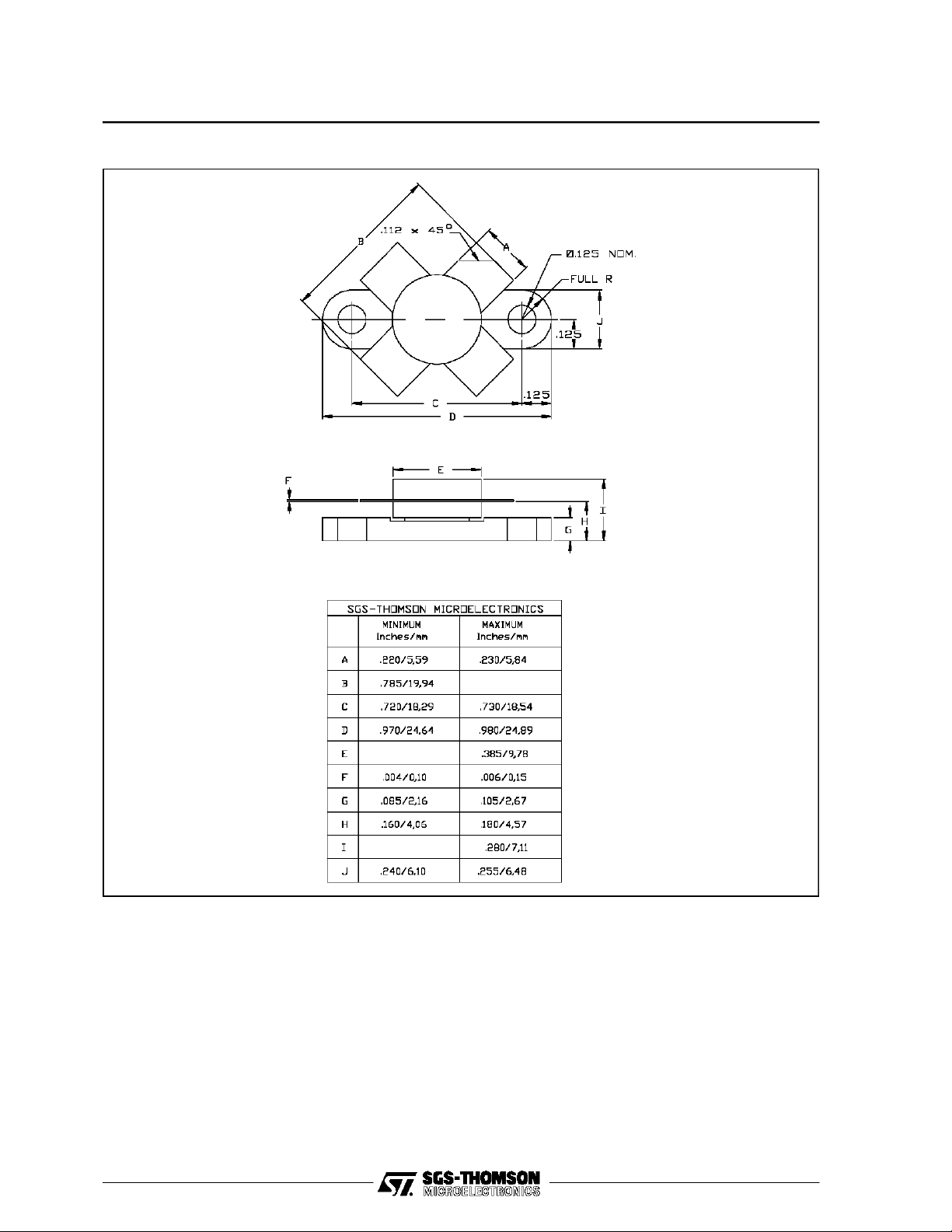
PACKAGE MECHANICAL DATA
Ref.: Dwg. No.12-0113
SD1446
Information furnished is believed to be accurate and reliable.However, SGS-THOMSON Microelectronicsassumes no responsability forthe
consequences of useof suchinformationnor for any infringementofpatents or other rights of third parties which mayresultsfromitsuse. No
license isgranted by implicationor otherwise underany patent orpatentrights ofSGS-THOMSON Microelectronics. Specificationsmentioned
in this publication aresubjectto changewithout notice.Thispublication supersedes and replaces allinformationpreviously supplied.
SGS-THOMSON Microelectronicsproducts arenotauthorized foruse ascritical componentsin lifesupport devicesorsystems withoutexpress
written approvalofSGS-THOMSONMicroelectonics.
1994 SGS-THOMSON Microelectronics- All RightsReserved
Australia - Brazil - France- Germany- HongKong - Italy-Japan - Korea - Malaysia - Malta - Morocco - The Netherlands -
Singapore - Spain - Sweden- Switzerland -Taiwan - Thailand - United Kingdom - U.S.A
SGS-THOMSON MicroelectronicsGROUP OF COMPANIES
5/5
 Loading...