

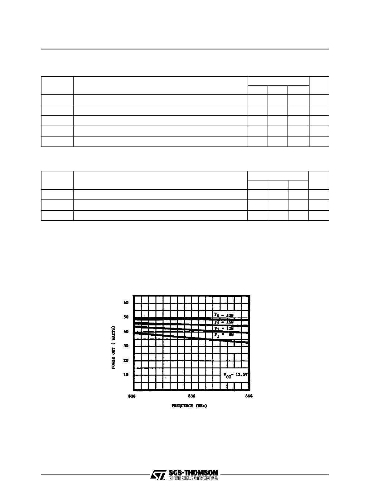
.836 MHz
.12.5 VOLTS
.COMMON BASE
.P
OUT
45 W MIN. WITH 4.7 dB GAIN
=
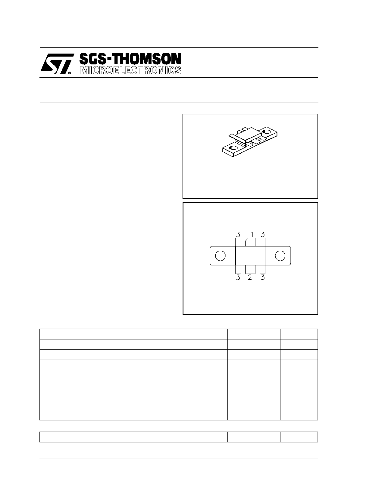
SD1414
RF & MICROWAVE TRANSISTORS
800-90 0 MHz APPLICAT IONS
.230 6LF L (M142)
epoxy sealed
ORDER CODE
SD1414
PIN CONNECTION
BRANDING
SD1414
DESCRIPTI ON
The SD1414 is a 12.5 V Class C epitaxial silicon
NPN planar transistor designed for amplifier applications in the 806 - 866 MHz frequency range.
Internal input matching and common base configuration assure optimum gain and efficiency
across the entire frequency band. The SD1414
withstands infinite VSWR at rated power output.
ABSOLUTE MAXIMUM RATINGS (T
Symbol Parameter Value Uni t
V
CBO
V
CEO
V
CES
V
EBO
I
C
P
DISS
T
J
T
STG
THERMA L DA TA
R
TH(j-c)
Collector-Base Voltage 36 V
Collector-Emitter Voltage 18 V
Collector-Emitter Voltage 36 V
Emitter-Base Voltage 4.0 V
Device Current 9.0 A
Power Dissipation 150 W
Junction Temperature +200
Storage Temperature
Junction-Case Thermal Resistance 1.2 °C/W
case
= 25°C)
1. Collector 3. Base
2. Emitter
65 to +150
−
°
C
°
C
March 1993
1/5
SD1414
ELECTRICAL SPECIFICATIO NS (T
case
= 25°C)
STATIC
Symbol Test Conditions
BV
BV
BV
I
CES
CEO
EBO
CBO
h
FE
IC= 50mA VBE= 0V 36 — — V
IC= 50mA IB= 0mA 18 — — V
IE= 10mA IC= 0mA 4.0 — — V
VCB= 15V IE= 0mA — — 5 mA
VCE= 5V IC= 1A 5 — 200 —
DYNAMIC
Symbol Test C ond itions
P
OUT
G
C
P
OB
f = 836 MHz PIN= 15 W VCE= 12.5 V 45 — — W
f = 836 MHz PIN= 15 W VCE= 12.5 V 4.7 — — dB
f = 1 MHz VCB= 12.5 V — 80 — pF
Value
Min. Typ. Max.
Value
Min. Typ. Max.
Unit
Unit
TYPICA L PERFO R MA NCE
POWER OU T PU T vs FREQ U ENCY
2/5

IMPEDA NCE DATA
SD1414
TYPICAL INPUT IMPEDANCE
TYPICAL COLLECTOR LOAD
IMPEDANCE
TYPICAL INPUT IMPEDANCE
TYPICAL COLLECTOR LOAD
IMPEDANCE
3/5

SD1414
TEST CIRCUIT
C1, C4 : 5pF ATC 100 mils Chip Capacitor
C2 : 1 - 12pFVariable Capacitor
C3 : .6 - 6pF Variable Capacitor
C5 : 2pF ”A” Size Chip Capacitor
C6, C7 : .6 - 12pF Voltronic Variable Capacitor
C8 : 480pF ATC 100 mils Chip Capacitor
C9 : 47µF, 63V, Electrolytic Capacitor
C10 : 1000pF Unelco Capacitor
L1, L2 : 5 Turns #24 AWG Enamel
Board Material: 3M-K-6098-1112.9mils Thick
4/5

PACKAGE MECHANICAL DATA
Ref.: Dwg. No.12-0142
SD1414
Information furnished is believed to be accurate and reliable.However, SGS-THOMSON Microelectronicsassumes noresponsability forthe
consequences of useof suchinformation nor for any infringementofpatents or other rights of third partieswhich mayresults from its use. No
license isgranted by implicationor otherwise underany patent orpatentrights ofSGS-THOMSON Microelectronics. Specificationsmentioned
in this publication aresubjectto changewithout notice. This publication supersedes andreplacesall information previously supplied.
SGS-THOMSON Microelectronicsproducts arenotauthorized foruse ascritical componentsin lifesupport devicesorsystems withoutexpress
written approvalofSGS-THOMSONMicroelectonics.
1994 SGS-THOMSON Microelectronics- All RightsReserved
Australia - Brazil - France- Germany- HongKong - Italy- Japan - Korea - Malaysia - Malta - Morocco -The Netherlands-
Singapore - Spain - Sweden- Switzerland-Taiwan - Thailand - United Kingdom -U.S.A
SGS-THOMSON MicroelectronicsGROUP OF COMPANIES
5/5
 Loading...