


HIGH VOLTAGE FAST-SWITCHING
■ STMicroelectronics PREFERRED
SALESTYPE
■ HIGH VOLTAGECAPABILITY
■ U.L.RECOGNISED ISOWATT218PACKAGE
(U.L. FILE # E81734(N).
APPLICATIONS:
■ HORIZONTAL DEFLECTIONFOR COLOUR
TV
DESCRIPTION
The S2000AFI is manufactured using
Multiepitaxial Mesa technology for cost-effective
high performance and uses a Hollow Emitter
structureto enhance switching speeds.
S2000AFI
NPN POWER TRANSISTOR
3
2
1
ISOWATT218
INTERNAL SCHEMATIC DIAGRAM
ABSOLUTE MAXIMUM RATINGS
Symb o l Parame t er Val u e Uni t
V
V
V
I
P
T
Collector-Emitter V oltage (VBE=0) 1500 V
CES
Collector-Emitter V oltage (IB= 0) 700 V
CEO
Emitter-Base Voltage (IC=0) 10 V
EBO
Collect or Current 8 A
I
C
Collect or Peak Cu rr ent (tp<5ms) 15 A
CM
Total Dis sipation at Tc=25oC50W
tot
Stora ge Temperat u re -65 to 15 0
stg
Max. O perati ng J unct ion T emperatu re 150
T
j
o
C
o
C
December 1999
1/6
S2000AFI
THERMAL DATA
R
thj-case
Ther mal Resistance J u nc tion-cas e Max 2.5
o
C/W
ELECTRICAL CHARACTERISTICS (T
=25oC unless otherwisespecified)
case
Symbol Parameter Test Cond itions Min. Typ. Max. Unit
I
CES
I
EBO
V
CEO(sus)
Collector Cut-off
Current (V
BE
=0)
Emit ter Cut-o f f Curr ent
=0)
(I
C
∗ Co llector-Emitter
V
=1500V TC=125oC
CE
=1500V
V
CE
V
=5V 100 µA
EB
I
= 100 mA 700 V
C
1
2
Sust aining Voltage
=0)
(I
B
V
V
CE(sat)
EBO
Emit ter Base Vo ltage
=0)
(I
C
∗ Collector-Emitter
I
=10mA 10 V
E
IC=4.5A IB=2A 1 V
Saturation Voltage
V
BE(sat)
∗ Base-Emitt er
IC=4.5A IB=2A 1.3 V
Saturation Voltage
INDUCTIV E LOAD
t
f
∗
Pulsed: Pulse duration =300 µs, duty cycle1.5 %
St orage Time
s
t
Fall Time
f
Tr ansition Frequency IC=0.1A VCE=5V f=5MHz 7 MHz
T
IC=4.5A hFE=2.5 VCC=140V
=0.9mH LB=3µH
L
C
7
0.55
mA
mA
µs
µs
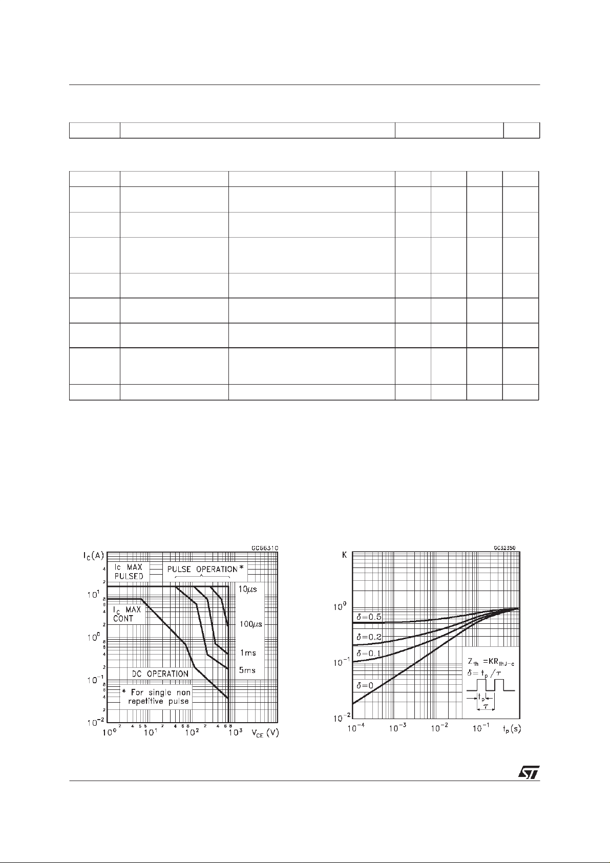
Safe OperatingArea. ThermalImpedance
2/6
S2000AFI
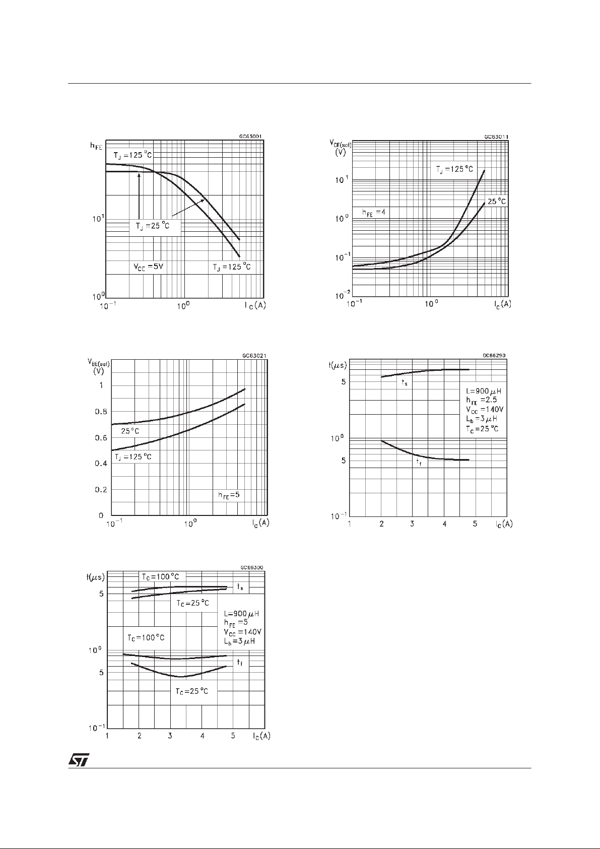
DCCurrent Gain
Base EmitterSaturationVoltage
Collector EmitterSaturationVoltage
SwitchingTimeInductiveLoad
SwitchingTime Inductive Load (see figure 1)
3/6

S2000AFI
Figure1: Inductive LoadSwitching TestCircuit.
4/6

ISOWATT218MECHANICALDATA
S2000AFI
DIM.
A 5.35 5.65 0.211 0.222
C 3.30 3.80 0.130 0.150
D 2.90 3.10 0.114 0.122
D1 1.88 2.08 0.074 0.082
E 0.75 0.95 0.030 0.037
F 1.05 1.25 0.041 0.049
F2 1.50 1.70 0.059 0.067
F3 1.90 2.10 0.075 0.083
G 10.80 11.20 0.425 0.441
H 15.80 16.20 0.622 0.638
L 9 0.354
L1 20.80 21.20 0.819 0.835
L2 19.10 19.90 0.752 0.783
L3 22.80 23.60 0.898 0.929
L4 40.50 42.50 1.594 1.673
L5 4.85 5.25 0.191 0.207
L6 20.25 20.75 0.797 0.817
N 2.1 2.3 0.083 0.091
R 4.6 0.181
DIA 3.5 3.7 0.138 0.146
MIN. TYP. MAX. MIN. TYP. MAX.
mm inch
- Weight : 4.9 g (typ.)
- Maximum Torque(applied to mountingflange) Recommended: 0.8 Nm; Maximum:1 Nm
- The side of thedissipator must beflat within 80µm
P025C/A
5/6

S2000AFI
Information furnished is believed tobe accurate andreliable. However, STMicroelectronics assumes no responsibility for the consequences
of use of such information nor for any infringement of patents or other rights of third parties which may result from its use. No license is
granted by implication orotherwise under any patent or patent rights of STMicroelectronics. Specification mentioned in thispublication are
subject tochange without notice. This publication supersedes and replaces allinformation previously supplied. STMicroelectronics products
are notauthorized for use as critical components in lifesupport devices or systems without express written approval of STMicroelectronics.
The ST logo is a trademark of STMicroelectronics
1999 STMicroelectronics – Printedin Italy – AllRights Reserved
STMicroelectronicsGROUP OFCOMPANIES
Australia - Brazil- China - Finland- France - Germany- Hong Kong - India- Italy - Japan - Malaysia - Malta - Morocco -
Singapore- Spain - Sweden - Switzerland -United Kingdom -U.S.A.
http://www.st.com
.
6/6
 Loading...