

Datasheet PFR850S, PFR851S, PFR852S, PFR854S, PFR856S Datasheet (SGS Thomson Microelectronics)
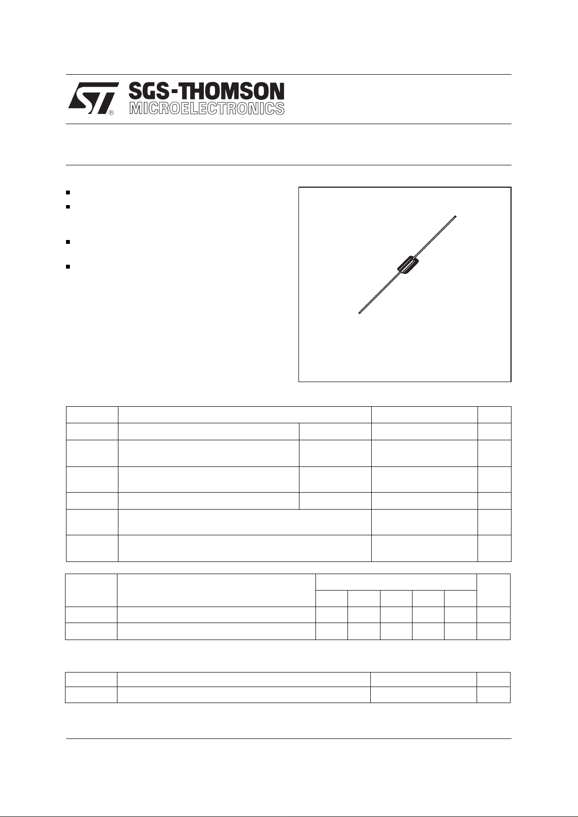
FAST RECOVER Y RECTIFIER DIODES
LOW FORWARD VOLTAGE DROP
HIGH SURGE CURRENT CAPABILITY
APPLICATIONS
AC-DC POWER SUPPLIES AND CONVERTERS
FREE WHEELING DIODES, etc.
PFR 850S → 856S
PRELIMINARY DATASHEET
DESCRIP TION
Their high efficiency and high reliability combined
with small size an d low cost m ak e thes e f ast reco-
DO-201AD
(Plastic)
very rectifier diodes v ery attractive c omponents for
many demanding applications.
ABSOLUTE MAXIMUM RATINGS (limiting values)
Symbol Parameter Value Unit
I
FRM
I
F (AV)
I
FSM
P
tot
T
stg
T
T
L
Symbol Parameter
Repetitive Peak Forward Current
Average Forward Current* T
Surge non Repetitive Forward Current tp = 10ms
Power Dissipation*
Storage and Junction Temperature Range - 40 to + 175
j
Maximum Lead Temperature for Soldering during 10s at 4mm from
case
≤ 20µs
t
p
90°C
a =
δ = 0.5
Sinusoidal
90°C
T
a =
PFR
850S 851S 852S 854S 856S
100 A
3A
100 A
3.5 W
- 40 to + 175
230
°C
°C
Unit
V
V
RRM
RSM
Repetitive P eak Re v erse Voltage 50 100 200 400 600 V
Non Repetitive Peak Reverse Voltage 75 150 250 450 650 V
THERMAL RES ISTANCE
Symbol Parameter Value Unit
R
th (j - a)
* On infinite heatsink with 10mm lead length.
August 1996 - Ed: 1
Junction-ambient* 25
°C/W
1/3
PFR 850S → 856S
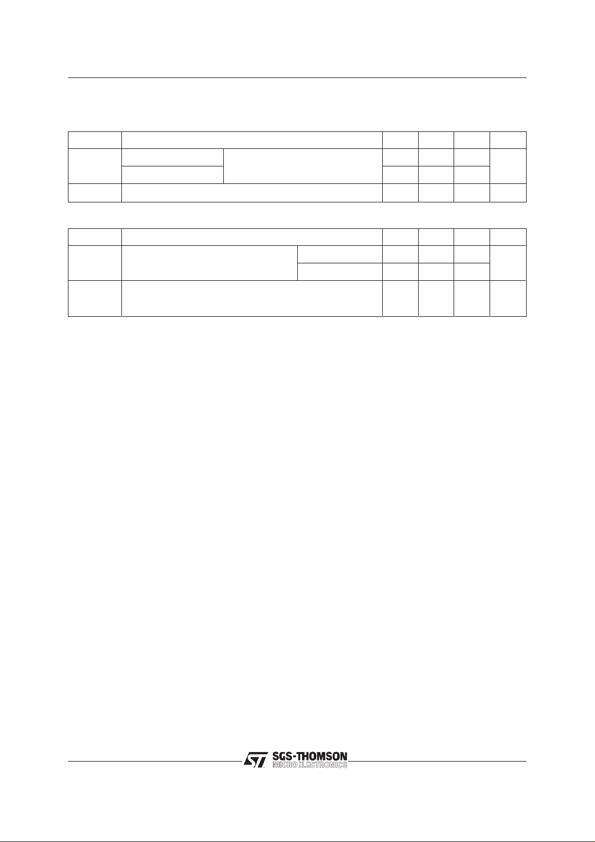
ELECTRICAL CHARACTERISTICS
STATIC CHARACTERISTICS
Synbol Test Conditions Min. Typ. Max. Unit
I
R
V
F
Tj = 25°C
= 100°C
T
j
Tj = 25°C
V
R
= V
RRM
10
250
I
= 3A 1.25 V
F
RECOVERY CHA R ACTERISTICS
Symbol Test Conditions Min. Typ. Max. Unit
t
rr
I
RM
Tj = 25°C I
= 30V diF/dt = - 25A/µs
V
R
Tj = 25°C I
V
= 30V diF/dt = - 25A/µs
R
= 1A PRF 850S →854S
F
= 1A
F
PRF 856S 200
150 ns
2A
µA
2/3

PACKAGE MECHANICAL D ATA
DO-201AD
PFR 850S → 856S
BA
note 1
E
B
note 1
E
ØD ØD
note 2
REF. DIMENSIONS NOTES
Millimeters Inches
Min. Max. Min. Max.
A 9.50 0.374
B 25.40 1.000
∅ C
∅ D
5.30 0.209
1.30 0.051
E 1.25 0.049
Weight : 1 g
Marking : Type number
White band indicates cathode
cooling method : by con v e rtion (method A)
Date code
1 - The lead diameter ∅ D is not controlled ov er z one E
2 - The minimum axial lengh within which the device may be
placed with its leads bent at right angles is 0.59"(15 mm)
ØC
Information furnished is believed to be accurate and reliable. However, SGS-THOMSON Microelectronics assumes no responsability for the
consequences of use of such information nor for any infringement of patents or other rights of third parties which may result from its use. No
license is granted by implication or otherwise under any patent or patent rights of SGS-THOMSON Microelectronics. Specificatio ns mentioned
in this publication are subject to change without notice. This public ation supersedes an d replaces all information pre vi ously supplied.
SGS-THOMSON Microelectronics products are not authorized for use as critical components in life support devices or systems without express
written approval of SGS-THOMSON Microelectronics.
© 1996 SGS-THOMSON Microelectronics - Printed in Italy - All rights reserved.
Australia - Brazil - Canada - China - France - Germany - Hong Kong - Italy - Japan - Korea - Malaysia - Malta - Morocco -
The Netherlands - Singapore - Spain - Sweden - Switzerland - Taiwan - Thailand - United Kingdom - U.S.A.
SGS-THOMSON Microelectronics GROUP OF COMPANIES
3/3
 Loading...