

SGS Thomson Microelectronics MSC1004M Datasheet
.1025 - 1150 MHz
.RUGGEDIZED VSWR ∞:1
.INTERNAL INPUT MATCHING
.LOW THERMAL RESISTANCE
.P
OUT
4.0 W MIN. WITH 9.0 dB GAIN
=
MSC1004M
RF & MICROWAVE TRANSISTORS
AVIONICS APPLIC ATIONS
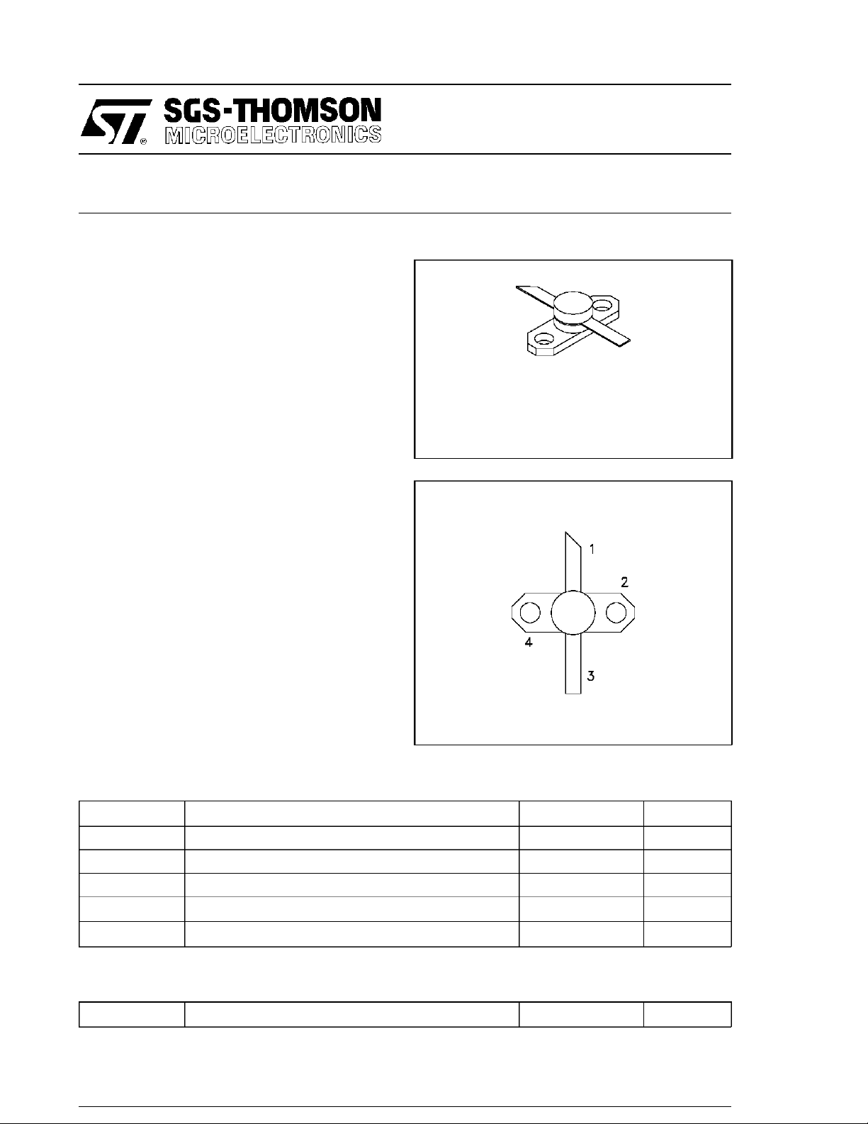
.280 2LFL (SO68)
epoxy sealed
ORDER CODE
MSC1004M
PIN CONNECTION
DESCRIPTION
The MSC1004M is a low-level Class C pulsed
transistor specifically designedfor DME/IFF driver
or output applications.
case
∞:1
1. Collector 3. Emitter
2. Base 4. Base
= 25°C)
18 W
− 65 to +150
These devices are capable of withstanding a
load VSWR at any phase angle under full rated
conditions. Low RF thermal resistance and automatic bonding techniques ensure high reliability
and product consistency.
The MSC1004M is housed in the IMPAC package with internal input matching.
ABSOLUT E MAXI MUM RATING S (T
Symbol Parameter Valu e Unit
P
T
DISS
I
V
T
STG
C
CC
J
Power Dissipation* (TC≤ 100°C)
Device Current* 650 mA
Collector-SupplyVoltage* 32 V
Junction Temperature 200
Storage Temperature
BRAND I NG
1004M
°
C
°
C
THERMAL DATA
R
TH(j-c)
*Appliesonly to ratedRF amplifier operation
June 12, 1995 1/3
Junction-CaseThermal Resistance* 5
°
C/W
MSC1004M
ELECTRICAL SPECIFICATIONS (T
case
= 25°C)
STATIC
Symbol T est Conditions
BV
CBO
BV
CER
BV
EBO I
I
CES V
h
FE V
IC= 1mA IE=0mA
IC= 5mA RBE= 10 Ω 45 — — V
= 1mA IC=0mA
E
= 28 V
CE
= 5V IC=200 mA
CE
DYNAMIC
Symbol Test C onditi ons
P
OUT
η
G
Note: Pulse Width=10µSec
f = 1025 − 1150 MHz P
cf=1025 − 1150 MHz P
f=1025 − 1150 MHz P
P
Duty Cycl e
1%
=
500 mW V
=
IN
500 mW V
=
IN
500 mW V
=
IN
CC
CC
CC
=
=
=
28 V
28 V
28 V
Value
Min. Typ. Max.
Unit
45 — — V
3.5 — — V
— 1.0 mA
30 — 300 —
Value
Min. Typ. Max.
4.0
35
9.0
Unit
—W
—%
—dB
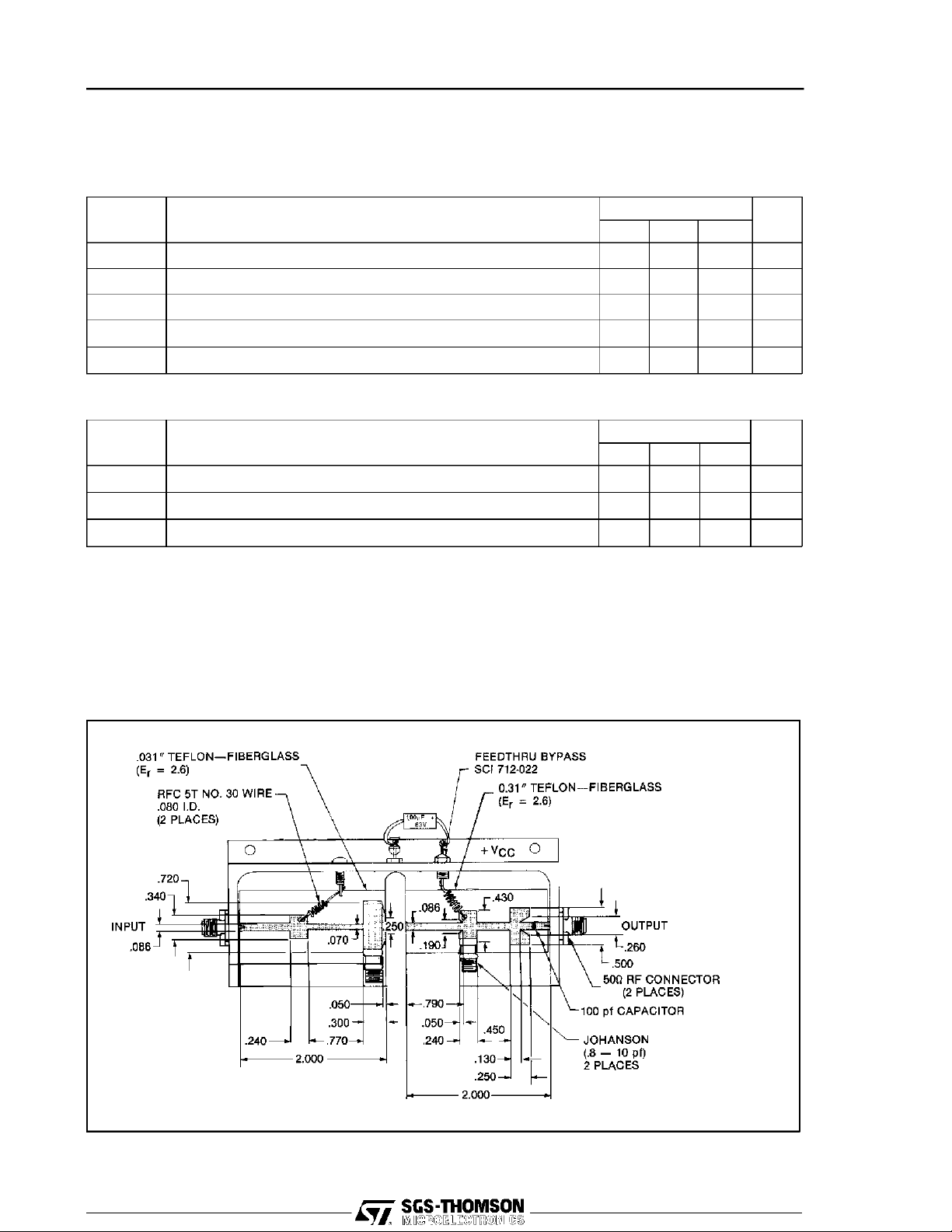
TEST CIRCUIT
Ref.: Dwg. No. C127299
All dimensions are in inches.
June 12, 1995 2/3
 Loading...