

MK50H25
HIGH SPEED
LINK LEVEL CONTROLLER
ADVANCE DATA
SECTION1 - FEATURES
System clock rate up to 33 MHz (MK50H25 -
33), 25 MHz (MK50H25 - 25), or 16 MHz
(MK50H25- 16).
Data rate up to 20 Mbps continuous
(MK50H25- 33) or up to51 Mbps bursted
On chip DMA control with programmableburst
length.
DMA transferrate of up to 13.3 Mbytes/secusing optional 5 SYSCLKDMA cycle (150 nS)at
33 MHz SYSCLK.
Complete Level 2 implementation compatible
with X.25 LAPB, ISDN LAPD, X.32, and X.75
Protocols.
Handles all error recovery, sequencing, and S
and U frame control.
Pin-for-pin and architecturally compatible with
MK5025 (X.25/LAPD), MK5027 (CCS#7) and
MK5029(SDLC).
BufferManagement includes:
- InitializationBlock
- SeparateReceive and TransmitRings
- VariableDescriptorRing and WindowSizes.
Separate64-byte Transmit andReceive FIFO.
Programmable Transmit FIFO hold-off water-
mark.
Handlesall HDLC frameformatting:
- Zero bit insertionand deletion
- FCS(CRC) generationand detection
- Framedelimitingwith flags
Programmable Single or Extended Address
and Control fields.
Five programmable timer/counters: T1, T3,
TP,N1, N2
Programmable minimum frame spacing on
transmission (number of flags between
frames).
- Programmable from 1 to 62 flags between
frames
Selectable FCS (CRC) of 16 or 32 bits, and
passingof entire FCSto buffer.
TestingFacilities:
- InternalLoopback
- SilentLoopback
- OptionalInternal DataClock Generation
- SelfTest.
Programmablefor full or halfduplexoperation
Programmable Watchdog Timers for RCLK
and TCLK(to detect absence ofdata clocks)
Option causing received data to effectively be
odd-byte aligned, in addition to standard evenbyte alignment.
Availablein 52 pin PLCC, 84 pin PLCC(foruse
with externalROM), or 48 pin DIP packages.
SECTION 2- INTRODUCTION
The SGS - Thomson MK502H5 Link Level Controller is a VLSI semiconductor device which provides complete link level data communications
control conforming to the 1984 and 1988 CCITT
versions of X.25. The MK50H25 will perform
frame formating including: frame delimiting with
flags, transparency (so-called ”bit-stuffing”), error
recovery by retransmission, sequence number
control, S (supervisory) and U (unnumbered)
frame control, plus FCS (CRC) generation and
detection. The MK50H25 also supports X.75 and
X.32 (with its XID frame support), as well as single channel ISDN LAPD (with its support of UI
frames andextended addressingcapabilities).
July 1994
DIP48
PLCC 52
1/64
For added flexibility a transparent mode provides
an HDLC transport mechanism without link layer
support. This flexible transparent mode may be
easily entered and exited without affecting the
X.25 link status or the link statevariables kept by
the MK50H25. In this mode no protocolprocessing is done and it is up to the user to takecare of
the upper level software. Single or extended Address field filtering and Control field handling are
optionallysupported withinthe transparentmode.
One of the outstanding features of the MK50H25
is its buffer management which includes on-chip
dual channel DMA. This feature allows users to
receive and transmit multiple data frames at a
time. (A conventionalserial communications control chip plus a separate DMA chip would handle
data for only a single block at a time.) The
MK50H25 will move multiple blocks of receive
and transmit data directly into and out of memory
through the Host’s bus. A possible system configurationfor the MK50H25 is shown in figure1.
The MK50H25 may be used with any of several
popular 16 and 8 bit microprocessors, such as
68020, 68000, 6800, Z8000, Z80, 8086, 8088,
80186, 80286,80386SX, etc.
The MK50H25 may be operated in either full or
half duplex mode. In half duplex mode, the RTS
and CTSmodem control pinsare provided. In full
duplex mode, these pins become user programmable I/O pins. All signal pins on the MK50H25
are TTL compatible. This has the advantage of
making theMK50H25 independentof the physical
interface. As shown in figure 1, line drivers and
receivers are used for electrical connectionto the
physicallayer.
DESCRIPTION (Continued)
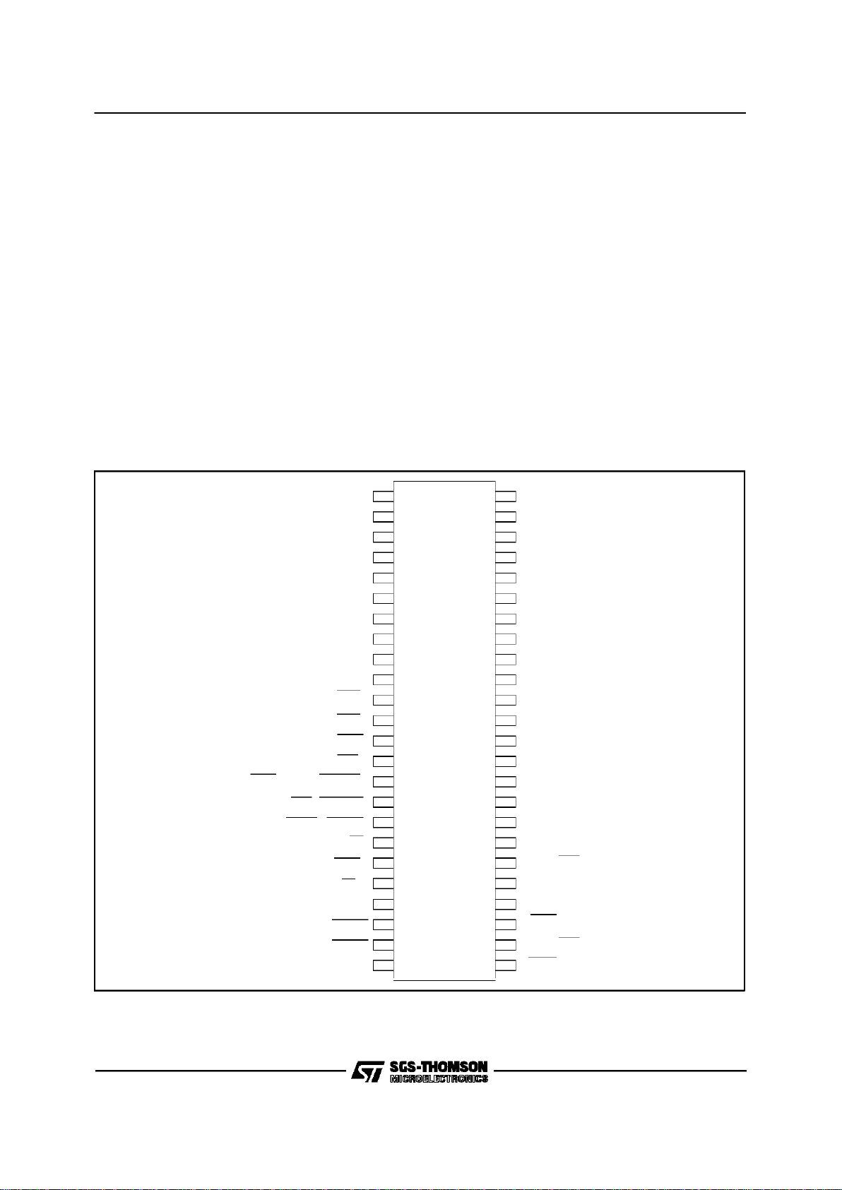
VSS-GND
DAL07
DAL06
DAL05
DAL04
DAL03
DAL02
DAL01
DAL00
READ
INTR
DALI
DALO
DAS
BMO, BYTE,BUSREL
BMI, BUSAKO
HOLD, BUSRQ
ALE, AS
CS
ADR
READY
RESET
VSS-GND
24
HLDA
1
2
3
4
5
6
7
8
9
10
11
12
13
14
48
47
46
45
44
43
42
41
40
39
38
37
36
23
22
21
20
19
18
17
16
15
35
34
33
32
31
30
29
28
27
26
25
TCLK
A18
A19
A20
A21
A22
A23
RD
DSR, CTS
TD
SYSCLK
RCLK
DTR, RTS
VCC (+5V)
DAL08
DAL09
DAL10
DAL11
DAL12
DAL13
DAL14
DAL15
A16
A17
M
K
5
0
H
2
5
DIP48 PIN CONNECTION (Topview)
MK50H25
2/64

VSS
DAL07
DAL06
DAL05
DAL04
DAL03
DAL02
DAL01
DAL00
READ
INTR
DALI
DALO
DAS
8
7 1 52 47
46
34
33
21
20
BMO/BYTE/BUSREL
No Connect
BM1/BUSAKO
HOLD/BUSRQ
ALE/AS
HLDA
CS
ADR
READY
RESET
VSS(GND)
TCLK
No Connect
DTR/RTS
RCLK
SYSCLK
TD
DSR/CTS
RD
A23
No Connect
A22
A21
A20
A19
A18
A17
A16
DAL15
DAL13
DAL14
VCC
DAL08
DAL09
DAL10
DAL11
DAL12
No Connect
MK50H25Q
PLCC52PIN CONNECTION (Top view)
MK50H25
3/64

SIGNAL NAME PIN(S) TYPE DESCRIPTION
DAL<15:00> 2-9
40-47
[2-10
44-51]
IO/3S The timemultiplexed Data/Address bus. During the address portion of a
memory transfer, DAL<15:00> contains the lower16 bits of the memory
address.
During the data portion of a memory transfer, DAL<15:00> contains the read
orwrite data, depending on the type of transfer.
READ 10
[11]
IO/3S READ indicatesthe type of operation that thebus controller is performing
during a bus transaction. READ is driven by the MK50H25 onlywhile it is the
BUS MASTER. READ is valid duringthe entirebus transaction and is
tristatedat all other times.
MK50H25 as a Bus Slave :
READ = HIGH - Data is placed on the DAL lines by the chip.
READ = LOW - Data is taken offthe DAL lines by the chip.
MK50H25 as a Bus Master :
READ = HIGH - Data is taken off the DAL lines by the chip.
READ = LOW - Data is placedon the DAL lines by the chip.
INTR 11
[12]
O/OD INTERRUPT is an attention interruptline that indicatesthat one or more of
thefollowing CSR0 status flagsis set: MISS, MERR, RINT, TINT or PINT.
INTERRUPT is enabled by CSR0<09>, INEA=1.
DALI 12
[13]
O/3S DAL IN is anexternal bus transceiver control line. DALI isdriven by the
MK50H25 onlywhile it isthe BUS MASTER. DALIis asserted by the
MK50H25 when it reads from the DAL linesduring the dataportion of a
READ transfer. DALIis not asserted during a WRITE transfer.
DALO 13
[14]
O/3S DAL OUT is an externalbus transceivercontrol line. DALO is driven by the
MK50H25 onlywhile it isthe BUS MASTER. DALOis asserted bythe
MK50H25 when it drives the DAL linesduring the address portionof a READ
transferor for the durationof a WRITE transfer.
DAS 14
[15]
IO/3S DATA STROBE defines thedata portion of a bus transaction. By definition,
datais stable and valid at thelow to high transition of DAS. This signalis
drivenby the MK50H25 whileit is the BUS MASTER. During theBUS
SLAVEoperation, this pin is used as an input. At allother times the signalis
tristated.
BMO
BYTE
BUSREL
15
[16]
IO/3S I/O pins 15 and 16 are programmable throughCSR4. If bit 06 ofCSR4 is set
to a one, pin 15becomes input BUSREL and is used by the host to signal
theMK50H25 to terminate a DMAburst afterthe current bus transfer has
completed. If bit 06 isclear then pin15 is an output and behaves as
described below for pin 16.
BM1
BUSAKO
16
[18]
O/3S Pins15 and 16 are programmable throughbit 00 ofCSR4 (BCON).
If CSR4<00> BCON = 0,
I/O PIN 15= BMO (O/3S)
I/O PIN 16 = BM1(O/3S)
BYTE MASK<1:0> Indicates the byte(s) on the DAL to be reador written
during this bus transaction. MK50H25 drives these lines onlyas a Bus
Master. MK50H25 ignoresthe BM lineswhen it is a Bus Slave.
Byte selection is done as outlined in the following table.
BM1 BM0 TYPE OF TRANSFER
LOW LOW ENTIRE WORD
LOW HIGH UPPER BYTE
(DAL<15:08>)
HIGH LOW LOWER BYTE
(DAL<07:00>)
HIGH HIGH NONE
TAble 1: PIN DESCRIPTION
LEGEND:
I Inputonly O Outputonly
IO Input / Output 3S 3-State
OD Open Drain(no internalpull-up)
Note: Pin out for 52 pin PLCCis shownin brackets.
MK50H25
4/64
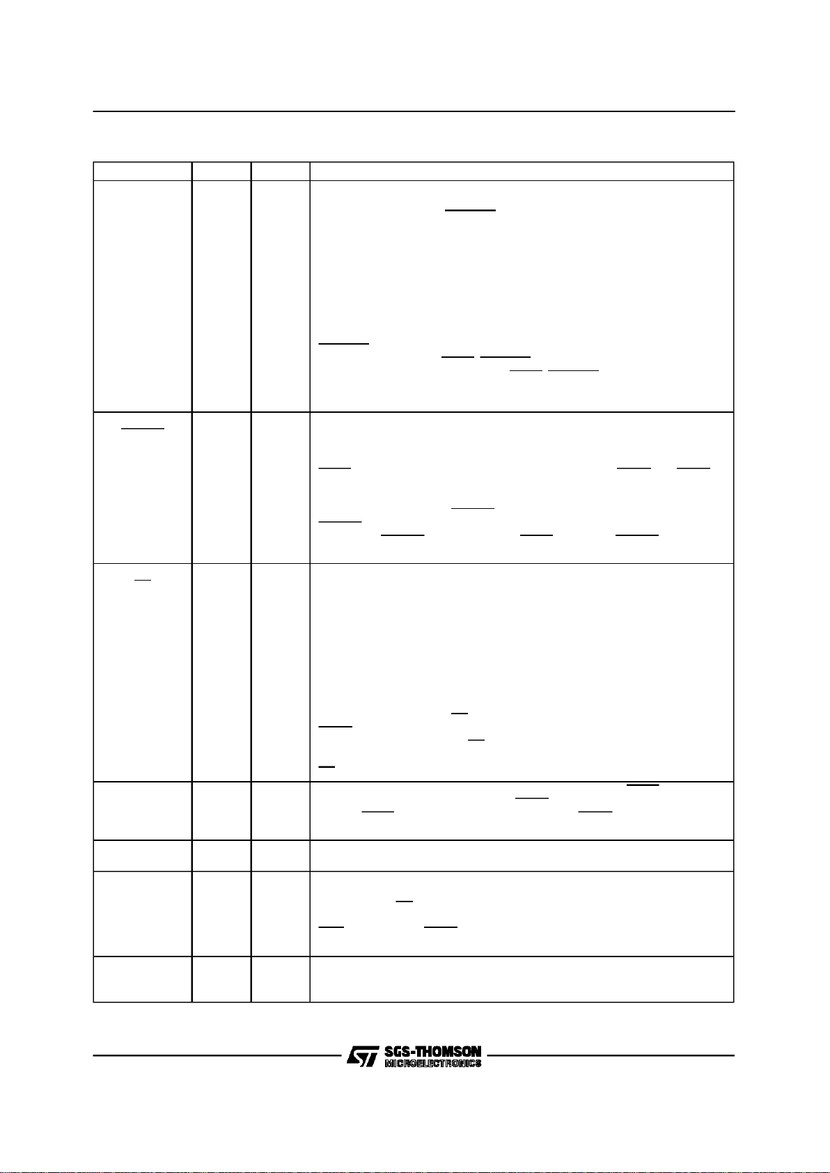
Table 1: PIN DESCRIPTION (continued)
SIGNAL NAME PIN(S) TYPE DESCRIPTION
If CSR4<00> BCON = 1,
I/O PIN 15 = BYTE (O/3S)
I/O PIN 16 = BUSAKO(O)
Byte selection is done using the BYTE lineand DAL<00> latched during the
addressportion of the bus transaction. MK50H25 drives BYTE only as a Bus
Master andignores it when a Bus Slave. Byte selectionis done as outlined
in the following table.
BYTE DAL<00> TYPE OF TRANSFER
LOW LOW ENTIRE WORD
LOW HIGH ILLEGAL CONDITION
HIGH LOW LOWER BYTE
HIGH HIGH UPPER BYTE
BUSAKOis a bus request daisy chainoutput. If MK50H25 isnot requesting
thebus and it receivesHLDA, BUSAKOwill be driven low. If MK50H25 is
requesting the bus when it receives HLDA, BUSAKOwill remain high
Note: Alltransfers areentire word unless the MK50H25 is configuredfor 8 bit
operation.
HOLD
BUSRQ
17
[19]
IO/OD Pin 17 is configured through bit 0 of CSR4.
If CSR4<00> BCON = 0,
I/O PIN 17= HOLD
HOLD request is asserted by MK50H25 when it requires a DMA cycle, if
HLDA is inactive, regardless of the previous state of the HOLDpin. HOLDis
heldlow for the entireensuing bus transaction.
If CSR4<00> BCON = 1,
I/O PIN 17 =BUSRQ
BUSRQ is asserted by MK50H25 whenit requires a DMA cycle if the prior
state of the BUSRQ pin was high andHLDA is inactive. BUSRQ is held low
for the entire ensuing bus transaction.
ALE
AS
18
[20]
O/3S The active level of ADDRESS STROBE is programmable through CSR4.
The addressportion of a bus transfer occurswhile this signal is at its
asserted level. This signal is driven by MK50H25 while it is the BUS
MASTER. At allother times, the signalis tristated.
If CSR4<01> ACON = 0,
I/O PIN 18 =ALE
ADDRESS LATCH ENABLE is used to demultiplex the DAL linesand define
theaddress portion of the transfer. As ALE, the signal transitions from high
to low during the address portion of thetransfer and remains low duringthe
dataportion.
If CSR4<01> ACON = 1,
I/O PIN 18 =AS
As AS, thesignal pulses low during the address portion of the bus transfer.
The lowto high transition of AScan be used by a slave device to strobe the
addressinto a register.
AS is effectively the inversionof ALE.
HLDA 19
[21]
I HOLD ACKNOWLEDGE is the response to HOLD. When HLDA is low in
response to MK50H25’s assertion of HOLD, the MK50H25 is the Bus
Master. HLDA should be deasserted ONLY after HOLD has been released
by theMK50H25.
CS 20
[22]
I CHIP SELECT indicates,when low, that the MK50H25 is the slave device
for the data transfer. CS must be validthroughout the entiretransaction.
ADR 21
[23]
I ADDRESS selects the Register Address Portor the Register Data Port. It
must be valid throughout the data portion of the transfer and is onlyused by
thechip when CS is low.
ADR PORT
LOW REGISTER DATA PORT
HIGH REGISTER ADDRESS PORT
READY 22
[24]
IO/OD When the MK50H25 is a Bus Master, READY is an asynchronous
acknowledgement from the bus memory thatmemory will accept data in a
WRITE cycle or that memory hasput data on the DAL linesin a READ cycle.
MK50H25
5/64
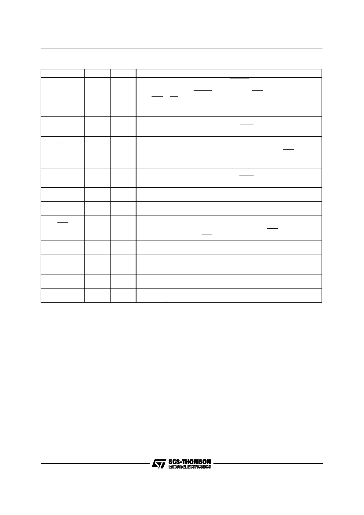
Table1: PINDESCRIPTION (continued)
SIGNAL NAME PIN(S) TYPE DESCRIPTION
As a Bus Slave, the MK50H25 asserts READY whenit has put data on the
DAL lines during a READ cycle or is about to take data from theDAL lines
during aWRITE cycle. READY is a response to DAS and it will be released
after DAS or CS is negated.
RESET 23
[25]
I RESET is the Bus signalthat will causeMK50H25 to cease operation, clear
its internal logic and enter an idlestate with thePower Off bit ofCSR0 set.
TCLK 25
[28]
I TRANSMIT CLOCK. A1x clock inputfor transmitter timing. TD changes on
the fallingedge of TCLK. The frequency of TCLK may not be greater than
the frequency of SYSCL
DTR
RTS
26
[29]
IO DATA TERMINAL READY, REQUEST TO SEND. Modem controlpin. Pin
26 is configurable throughCSR5. This pin can be programmed to behave as
output RTS or as programmable IO pin DTR. Ifconfigured as RTS, the
MK50H25 will assert this pin if it has data to send and throughout the
transmission of a signal unit.
RCLK 27
[30]
I RECEIVE CLOCK. A 1xclock input for receiver timing. RD issampled on
the risingedge of RCLK. The frequency of RCLK may not be greater than
the frequency of SYSCLK.
SYSCLK 28
[31]
I SYSTEM CLOCK. System clock used for internal timing of the MK50H25.
SYSCLK should be a square wave, of frequency up to 33 MHz.
TD 29
[32]
O TRANSMIT DATA. Transmit serial data output.
DSR
CTS
30
[33]
IO DATA SET READY, CLEAR TO SEND.Modem Control Pin.Pin 30 is
configurablethrough CSR5. This pin can be programmed to behave as input
CTS or as programmable IO pin DSR. If configured as CTS,the MK50H25
will transmitall ones whileCTS is high.
RD 31
[34]
I RECEIVE DATA. Received serial data input.
A<23:16> 32-39
[37-43]
o/3s Address bits <23:16>used in conjunction with DAL<15:00> toproduce a 24
bit address. MK50H25 drives these lines only as a Bus Master. A23-A20
may be driven continuously as describedin the CSR4<7>BAE bit.
VSS-GND 1,24
[1,26]
Ground Pins
VCC 48
[52]
Power Supply Pin
+5.0 VDC + 5%
SECTION3
OPERATIONALDESCRIPTION
The SGS-Thomson MK50H25 Multi-Logical Link
CommunicationsControllerdevice isa VLSIproduct intended for high performancedata communication applications requiring X.25 link level control. The MK50H25 will perform all frame
formatting, such as: frame delimiting with flags,
FCS (CRC) generation and detection, and zero
bit insertion and deletion for transparency. The
MK50H25 also handles all supervisory (S) and
unnumbered (U) frames (see Tables A & B). The
MK50H25 also includes a buffer management
mechanismthat allowsthe user totransmit and/or
receive multiple frames for each active channel
or DLCI. Contained in the buffer management is
an on-chip dual channel DMA:one channel for receiveand one channelfor transmit.
The MK50H25 can be used with any popular 16
or 8 bit microprocessor. A possible system configuration for the MK50H25 is shown in Figure 1.
This document assumesthat the processorhas a
byte addressablememoryorganization.
The MK50H25 will move multiple blocks of receive and transmit data directly in and out of
memory throughthe Host’sbus.
The MK50H25 may be operated in full or half duplex mode. In half duplex mode the RTS and
CTS modem control pins are provided. In full duplex mode, these pins become user programmable I/O pins.
All signalpins on the MK50H25 are TTL compatible. This has the advantage of making the
MK50H25 independent of the physical interface.
As shown in Fig. 1, line drivers and receiversare
used for electrical connection to the physical
layer.
MK50H25
6/64
HOST PROCESSOR
(68000, 80186, Z8000, ETC)
16-BIT DATA BUS INCLUDING
24-BIT ADDRESS AND BUS CONTROL
MEMORY
(MULTIPLE
DATA BLOCKS)
MK50H25
RD
TD
LINE DRIVERS
AND RECEIVERS
(SUCH AS RS-449, RS-232C, V.35)
DATA COMM. CONNECTOR
ELECTRICAL I/O
(SUCH AS RS-232C, RS-423, RS-422)
TCLK
RCLK
DSR, CTS
DTR, RTS
Figure1: Possible System Configurationfor thr MK50H25
MK50H25
7/64

DALI
DALO
HLDA
HOLD
ALE, AS
BM0
BM1
DAS
READ
INTR
ADR
READY
DTR, RTS
DSR, CTS
CS
FIRMWARE
ROM
MICRO
CONTROLLER
TIMERS
DMA
CONTROLLER
CONTROL / STATUS
REGISTERS 0 - 5
SYSCLK
INTERNAL BUS
RECEIVER
FIFO
TRANSMITTER
FIFO
RECEIVER TRANSMITTER
LOOPBACK
TEST
RD
RCLK
TCLK
TD
VSS - GND
RESET
VCC
DAL<15:00>
A <23:16>
Figure2: MK50H25Simplified BlockDiagram
MK50H25
8/64

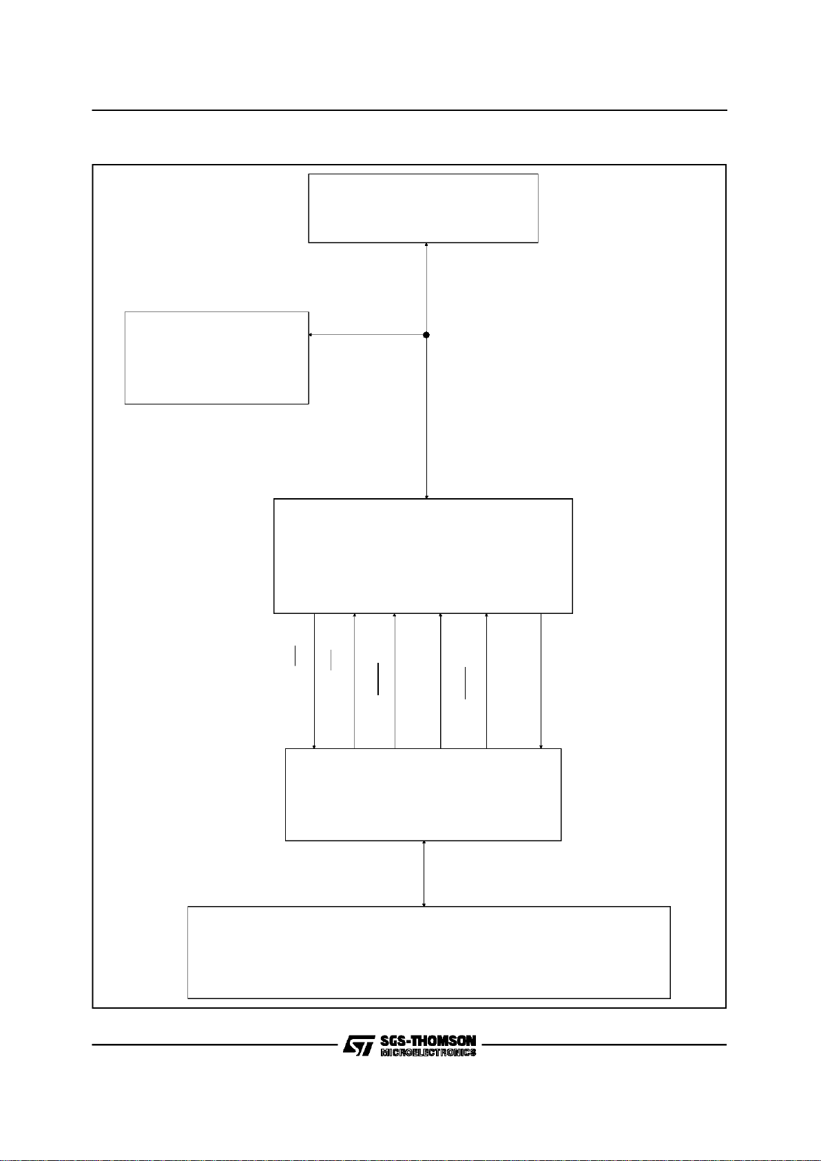
3.1 FunctionalBlocks
Refer tothe blockdiagram in Figure2.
The MK50H25 is primarily initialized and control-
led through six 16-bit Control and Status Registers (CSR0 thru CSR5). The CSR’s are accessed
through two bus addressable ports, the Register
Address Port (RAP), and the Register Data Port
(RDP). The MK50H25 may also generate an interrupt(s) to the Host. These interrupts are enabledand disabled throughCSR0.
The on-chip microcontroller is used to control the
movement of parallel receive and transmit data,
and to handle the Addressfield filtering.
3.1.1 Microcontroller
Themicrocontroller controlsall of the otherblocks
of the MK50H25. The microcontroller performs
frame processing and protocol processing. All
primitive processing and generation is also done
here. The microcode ROM contains the control
programof the microcontroller.
3.1.2 Receiver
Serial receive data comes into the Receiver (Figure 2). The Receiver is responsiblefor:
1.Leading and trailingflag detection.
2.Deletion of zeroesinserted for transparency.
3.Detection of idle and abort sequences.
4.Detection of good and bad FCS (CRC).
5. MonitoringReceiverFIFO status.
6.Detection of ReceiverOver-Run.
7. Oddbyte detection.
NOTE: If framesare receivedthat have an odd
numberof bytes then thelast byteof the
frame is said to be anodd byte.
8.Detection of non-octet aligned frames.Such
framesare treated as invalid (CCITT X.25 sec
2.3.5.3)
3.1.3 Transmitter
The Transmitteris responsiblefor:
1. Serializationof outgoingdata.
2. Generatingand appendingthe FCS(CRC).
3. Framing outgoingframe with flags.
4. Zerobit insertion fortransparency.
5. TransmitterUnder-Run detection.
6. Transmissionof odd byte.
7.RTS/CTScontrol.
3.1.4 Frame Check Sequence orCyclic
Redundancy Check
The FCS (CRC) on the transmitter or receiver
may be either 16 bit or 32 bit, and is user selectable. For full duplex operation, both the receiver
and transmitter have individual FCS computation
circuits. The characteristics ofthe FCS are:
TransmittedPolarity: Inverted
TransmittedOrder: High OrderBit First
Pre-setValue: All 1’s
Polynomial16 bit:
X
16+X12+X5
+1
Remainder16 bit (if received correctly):
Highorder bit-->0001 11010000 1111
Polynomial32 bit:
X
32+X26+X23+X22+X16+X12+X11+X10
+
X
8+X7+X5+X4+X2
+X+1
Remainder32 bit (if received correctly):
high order bit-->1100 0111 00000100
1101 11010111 1011
3.1.5 Receive FIFO
The Receive FIFO buffers the data received by
the receiver. This performs two major functions.
First, it resynchronizes the data from the receive
clock to the system clock. Second, it allows the
microcontroller time to finish whatever it may be
doing beforeit has to processthe receiveddata.
The receiveFIFO holds the data from the receiver
without interrupting the microcontroller for service
until it contains enough data to reach the watermark level, or an end of frame is received. This
watermark level can be programmed in CSR4
(FWM) to occur when the FIFO contains at least
18 or more bytes; 34 or more bytes; or 50 or
more bytes. This programmability, along withthe
programmableburst length of the DMAcontroller,
enables the user to definehow often and for how
long the MK50H25 must use the host bus. For
more information,see CSR4.
For example, if the watermark level is set at 34
bytes and the burst length is limited to 8 word
transfers at a time, the MK50H25 will request
control of the host bus as soon as 34 bytes are
received and again after every 16 subsequent
bytes.
3.1.6 Transmit FIFO
The Transmit FIFO buffers the data to be transmitted by the MK50H25. This also performs two
major functions. First, it resynchronizesthe data
from the systemclock to the transmitclock. Second, it allows the microcontroller and DMA controller to burst read data from the host’s memory
buffers; making both the MK50H25 and the host
bus more efficient.
The transmit FIFO hasa watermarkscheme similar to the one described for the receive FIFO
above, and uses the sameFWM value selections
in CSR4 for the watermark. Once filled to within
MK50H25
9/64

FWM of being full (by DMA from TX buffer in
shared memory), the transmit FIFO will not interrupt the microcontroller until it emptiesenough to
fall below the watermarklevel.
The transmit FIFO also has a selectableTransmit
Hold-Off watermark mechanism to determine
when data transmission will begin once data has
been put in the transmit FIFO. The Transmit
Hold-Off watermark is enabled by setting bit 10
(XHOLD) in CSR4. The selection of FWM (FIFO
WaterMark) also in CSR4 determines corresponding appropriate values of TransmitHold-Off
so that the device cannot be inadvertently programmed to have conflicting watermarks. For
FWM settings of 9, 17, and 25 words, the Transmit Hold-Off watermarks are 19, 11, and 3 words
respectively.
For example, if FWM is set at 9 words and the
Transmit Hold-Off watermark is enabled, the
MK50H25 will not begin transmitting until more
than 19 words have been placed in the Transmit
FIFO or an end-of-frame has been transmitted.
This greatly reduces the chances of Transmitter
Underrunthat could be possible at highdata rates
(ie: TCLK > 0.15 x SYSCLK) if Transmit Hold-Off
is not selected (causing transmission to begin as
soonas 1byte is transferredto the TX FIFO).
3.1.7 DMA Controller
TheMK50H25 has an on-chip DMAControllercircuit. This allows it to access memory without requiring host software intervention. Wheneverthe
MK50H25 requires access to the host memory it
will negotiate for mastership of the bus. Upon
gainingcontrol of thebus the MK50H25 willbegin
transferring data to or from memory. The
MK50H25 will perform memory transfers until
either it has nothing more to transfer, it has
reached its DMA burst limit (user programmable),
or the BUSREL pin is driven low. In any case, it
will complete all bus transfers before releasing
bus mastership back to the host. If during a
memory transfer, the memory does not respond
within 256 SCLK cycles, the MK50H25 will release ownership of the bus immediately and the
MERR bit will be set in CSR0. The DMA burst
limit can be programmed by the user through
CSR4. In 16 bit mode the limit can be set to 1
word, 8 words, or unlimited word transfers. In 8
bit mode,it can be set to 2 bytes, 16 bytes, or unlimited byte transfers. For high speed data lines
(i.e. > 1 Mbps)a burst limit of 8 words or 16 bytes
issuggested to allow maximumthroughput.
The byte ordering of the DMA transfers can be
programmedto account for differencesin processor architectures or hostprogramming languages.
Byte ordering can be programmed separately for
data and control information. Data information is
defined as all contents of data buffers; control information is defined as anything else in the
shared memoryspace (i.e. initialization block,descriptors, etc). For more information see section
4.1.2.5 on control statusregister 4.
3.1.8 Bus Slave Circuitry
The MK50H25 contains a bank of internal control/status registers (CSR0-5) which can be accessed by the hostas a peripheral. The host can
read or write to these registers like any other bus
slave. The contents of these registers are listed
in Section4 and bus signal timing is described in
Figures 9and 10.
3.2 Buffer ManagementOverview
Refer to Fig.3.
3.2.1 Initalization Block
Chip initialization information is located in a block
of memory called the Initialization Block. The Initialization Block consists of 25 contiguous words
of memory starting on a word boundary. This
memory is assembled by the HOST, and is accessed by the MK50H25during initialization. The
InitializationBlock iscomprised of:
A. Modeof Operation.
B. FrameAddress Values.
C. N1 Counter (Max FrameLength) Value.
D. Timer Preset Values
E. Locationand size ofReceive and TransmitDe-
scriptor Rings.
F. Locationand size ofXID/TEST Buffers.
G. Location ofStatus Buffer.
H. ErrorCounters.
3.2.2 The Circular Queue
The basic organization of the buffer management
is a circular queue of tasks in memory called descriptor rings. There are separate rings to describe the transmit and receive operations. Up to
128 buffers may be queued-up on a descriptor
ring awaiting execution by the MK50H25. The
descriptor ring has a descriptor assignedto each
buffer. Each descriptor holds a pointer for the
starting address of the buffer, and holds a value
for the lengthof the bufferin bytes.
Each descriptor also contains two control bits
called OWNA and OWNB, which denote whether
the MK50H25, the HOST, or the I/O ACCELERATION PROCESSOR( if present ) ”owns” the buffer. For transmit, when the MK50H25 owns the
buffer, the MK50H25 is allowed and commanded
to transmit the buffer. When the MK50H25 does
not own the buffer, it will not transmit that buffer.
For receive, when the MK50H25owns a buffer, it
may place received data into that buffer. Conversely, when the MK50H25 does not own a receive buffer, it will not place received data into
that buffer.
The MK50H25 buffer management mechanism
will handle frames which are longer than the
length of an individual buffer. This is done by a
chaining method which utilizes multiple buffers.
The MK50H25 tests the next descriptor in the de-
MK50H25
10/64
scriptor ring in a ”look ahead” manner. If the
frame is too long for one buffer, the next buffer
will be used after filling the first buffer; that is,
”chained”. The MK50H25 will then ”look ahead”
to the next buffer, and chain that buffer if necessary, and so on.The operational parameters for
the buffer managementare defined by the user in
the initialization block. The parameters defined
include the basic mode of operation, the number
of entries for the transmitter and receiver descriptor rings, frame Address field, etc. The starting
address for the Initialization block, IADR, is defined in the CSR2 and CSR3 registers inside the
MK50H25.
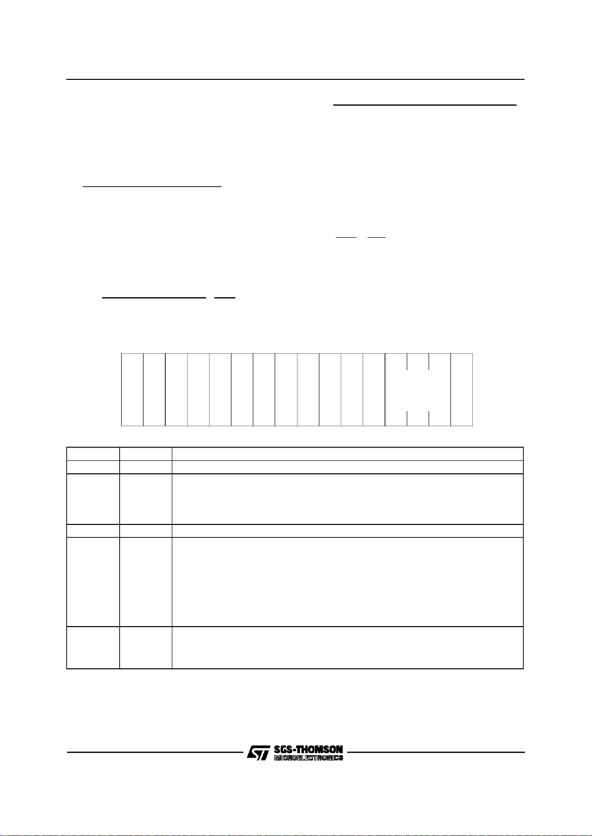
3.2.3 FrameFormat
The frame format supported by the MK50H25 is
shown below. Each frame may consistof a programmable number of leading flag patterns
(01111110), an address field, a control field, an
informationfield, an FCS (CRC) ofeither 16 or 32
bits, and a trailing flag pattern. The number of
leading flags transmitted is programmable
through the Mode Register in the Initialization
Block. Received frames may have as few as one
flagbetween adjacentframes
TRANSMITTED FIRST
3.2.4 TheCommand/ResponseRepertoire
The command/response repertoire of the
MK50H25 is shown in Tables A and B. This set
conforms to the 1984 & 1988 CCITT X.25, plus
supportof XID, Test,and UI frames conformingto
ISDN LAPD. The MK50H25 will process the Information, Supervisory, and Unnumbered frames
shown in Tables A and B, and will handle the A
and C fieldsfor all I and UIframes.
The symbols and definitions for the frame types
are:
Name Definition
I Information frame
UI Unnumbered Information frame
RR ReceiverReady
RNR Receiver Not Ready
REJ Reject
FRMR Frame Reject
UA Unnumbered Acknowledge
SABM Set Asynchronous Balance Mode
DISC Disconnect
DM Disconnect Mode
TEST Link Test Frame
XID Exchange Identification
AC
INFO
F
8/16 8/16
8*n
8
F FCS
8
16/32
MK50H25
11/64

Table A - MK50H25Command/Response Repertoire
Modulo 8 Operation
FORMAT COMMAND RESPONSE ENCODING
LSB MSB
12345678
InformationTransfer I I 0 ← N(S)
→ P ← N(R) →
Supervisory RR RR 1 0 0 0 P/F ← N(R) →
RNR RNR 1 0 1 0 P/F ← N(R) →
REJ REJ 1 0 0 1 P/F ← N(R) →
Unnumbered
*
UI
*
UI 1100P/F000
SABM 1 1 1 1 P 1 0 0
DM 1111F000
DISC 1 1 0 0 P 0 1 0
UA 1100F110
FRMR 1 1 1 0 F 0 0 1
*
XID
*
XID 1 1 1 1 P/F 1 0 1
TEST TEST 1 1 0 0 P/F 1 1 1
Table B - MK50H25Command/Response Repertoire
Modulo128 Operation
FORMAT COMMAND RESPONSE ENCODING
LSB MSB
1 2 3 4 5 6 7 8 9 10-16
Information
Transfer
I I 0 N(S) P N(R)
Supervisory RR RR 1 0 0 0 0 0 0 0 P/F N(R)
RNR RNR 1 0 1 0 0 0 0 0 P/F N(R)
REJ REJ 1 0 0 1 0 0 0 0 P/F N(R)
Unnumbered SABME 1 1 1 1 P 1 1 0 N/A
All Others AllOthers
Same Repertoire and Encoding as forModulo 8
Notes:
1. N(S) = Transmitter Send Sequence Number
2. N(R) =Transmitter Receive Sequence Number
3. P/F = Poll bit when issued as acommand. Final bit when issued as a response.
4. N/A = Not Applicable. All Unnumbered frames have only an 8 bitControl Field for Modulo 128 orModulo 8 operation.
*XID and UI frames can be enabled individually by setting the appropriate bits in CSR2.
MK50H25
12/64

RECEIVER DESCRIPTOR RINGS
DESCRIPTOR 0
BUFFER STATUS
BUFFER ADDRESS
BUFFER SIZE
BUFFER MSG COUNT
DESCRIPTOR 1
DESCRIPTOR M
TRANSMIT DESCRIPTOR RINGS
DESCRIPTOR 0
BUFFER STATUS
BUFFER ADDRESS
BUFFER SIZE
BUFFER MSGCOUNT
DESCRIPTOR 1
DESCRIPTOR N
BUFFER
N
BUFFER
1
BUFFER
0
TRANSMIT BUFFER
BUFFER
M
BUFFER
1
BUFFER
0
RECEIVE BUFFER
CSR 2, CSR3
POINTER TO
INITIALIZATI ONBLOCK
INITIALIZATI ONBLOCK
MODE
TIMER VALUES
RX DESCRIPTOR
TX DESCRIPTOR
POINTER
POINTER
FRAME ADDRESS
FIELDS
STATUS
BUFFER ADDRESS
STATUS BUFFER
ERROR COUNTERS
XID/TEST TRANSMIT
DESCRIPTOR POINTER
XID/TEST RECEIVE
DESCRIPTOR POINTER
RECEIVE BUFFER
TRANSMIT BUFFER
XID/TEST
XID/TEST
Figure3: MK50H25Memory ManagementStructure
MK50H25
13/64
SECTION4
PROGRAMMING SPECIFICATION
This section defines the Control and Status Registers and the memory data structuresrequired to
programthe MK50H25.
4.1 Control andStatus Registers
There are six Control and Status Registers
(CSR’s) resident within the MK50H25. The
CSR’s are accessed through two bus addressable ports, an address port (RAP), and a data
port (RDP), thus requiring only two locations in
the system memory orI/O map.
4.1.1 Accessin gthe Control &StatusRegiste rs
The CSR’s are read (or written) in a two step operation. Theaddress of theCSR is written into the
address port (RAP) during a bus slave transaction. During a subsequentbus slave transaction,
the data being read from (or written into) the data
port (RDP) is read from (or written into) the CSR
selected in the RAP. Once written, the addressin
RAP remains unchanged until rewritten or upon a
bus reset. A control I/O pin (ADR) is provided to
distinguishthe addressport from the data port.
ADR Port
L RegisterData Port(RDP)
H Register AddressPort (RAP)
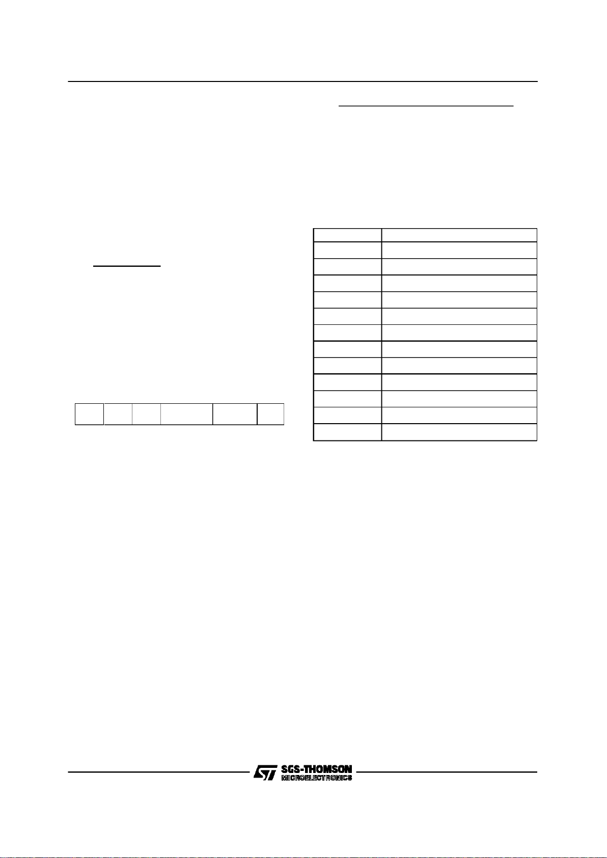
4.1.1.1 Register Address Port (RAP)
00000000
B
M
8
000
CSR
<2:0>
15141
3
0
7
0
8
1
0
1
1
1
2
0
1
0
2
0
3
0
4
0
5
0
0
0
9
0
6
H
B
Y
E
T
BIT NAME DESCRIPTION
15:08 RESERVED Must be written as zeroes
07 BM8 When set, places chip into 8 bitmode. CSR’s, Init Block, and data transfersare all 8bit
transfers; this providescompatibility with 8 bitmicroprocessors. When clear, alltransfers
are 16 bit transfers. This bit must be set to the same value each time it is written,
changing this bit during normal operation will achieve unexpected results. BM8 is
READ/WRITE and cleared on Bus RESET.
06:04 RESERVED Must be written as zeroes
03:01 CS3<2:0> CSR address selectbits. READ/WRITE. Selects the CSR to be accessed through the
RDP. RAP is cleared by Bus RESET.
CSR<2:0> CSR
0 CSR0
1 CSR1
2 CSR2
3 CSR3
4 CSR4
5 CSR5
00 HBYTE Determines which byte is addressed for 8 bit mode. If set, the high byteof the register
referred to byCSR<2:0> is addressed,otherwise the low byte is addressed. This bit is
only meaningful in8 bit mode and must be writtenas zero if BM8=0. HBYTE is
READ/WRITE and cleared on bus reset.
MK50H25
14/64

CSR DATA
1
5
1
0
1
4
0
9
121
1
0
8
0
3
0
7
0
2
06050
4
010
0
1
3
4.1.1.2 Register Data Port (RDP)
BIT NAME DESCRIPTION
15:00 CSR DATA Writing data tothe RDP loadsdata into the CSR selectedby RAP. Reading the data from
RDP reads the data from the CSR selected inRAP.
MK50H25
15/64

4.1.2 Control and Status Register Definition
4.1.2.1 Controland Status Register 0 (CSR0)
RAP<3:1> =0
BIT NAME DESCRIPTION
15 TDMD TRANSMITDEMAND, when set, causes the MK50H25 access the
Transmit Descriptor Ring without waiting for the Transmit poll time interval to lapse. TDMD need not be set to transmit a frame, it merely
hastens the MK50H25’s response to a Transmit Descriptor Ring entry
insertion by the host. TDMD is written with ONE ONLY and cleared by
the MK50H25 microcode after it is used. It may read as a ”1” for a
short time after it is written because the microcode may have been
busy when TDMDwas set. Itis also cleared byBus RESET. Writing a
”0” in this bithas no effect.
14 STOP STOP,when set, indicatesthat MK50H25 is operatingin theStopped
phase of operation. All externalactivity is disabled and internallogic is
reset. MK50H25 remainsinactive except for primitive processing until
a START primitive is issued. STOP IS READ ONLY and set by Bus
RESET ora STOP primitive. Writing to thisbit has no effect.
13 DTX DisableTransmitter ring prevents the MK50H25from furtheraccess to
the Transmitter Descriptor Ring. No transmissions are attempted after
finishing transmission of any frame in transmission at the time of DTX
being set. TXON acknowledgeschanges to DTX, see below. DTX is
READ/WRITE.
12 DRX Disable theReceiver prevents the MK50H25 fromfurther access tothe
Receiver Descriptor Ring. No received frames are accepted after finishing receptionof any frame in receptionat the time of DRX being set.
If DRX is set while a data link is established, the MK50H25 will go into
the Local Busy state and will send an RNR response frame to the remote station. Upon clearing DRX the MK50H25 will send a RR response frame. RXON acknowledges changes to DRX, see description
of RXON. DRX is READ/WRITE.
11 TXON TRANSMITTER ON indicates that thetransmit ring accessis enabled.
TXON is setas the Startprimitive is issuedif theDTX bit is ”0” or afterward as DTX is cleared. TXON is clearedupon recognition of DTXbeing set, by sending a Stop primitive in CSR1, or by a Bus RESET. If
TXON is clear, the host may modify the Transmit Descriptor Ring entries regardless of the state of the OWNA bits. TXON is READ ONLY;
writing to thisbit has no effect.
10 RXON RECEIVERON indicates that the receive ring access is enabled.
RXON isset as the Startprimitive isissued if the DRX bit is ”0” or afterward as DRX is cleared. RXON is cleared upon recognition of DRX
being set, by sendinga Stop primitive in CSR1, or by a Bus RESET. If
RXON is clear, the host may modify the Receive Descriptor Ring entries regardless of the state of the OWNA bits. RXON is READ ONLY;
writing to thisbit has no effect.
15141
3
0
7
0
8
1
0
1
1
1
2
0
1
0
2
0
3
0
4
0
5
0
0
0
9
0
6
0
R
I
N
T
T
I
N
T
P
I
N
T
T
U
R
M
I
S
S
M
E
R
R
R
O
R
I
N
T
R
R
X
O
N
T
X
O
N
I
N
E
A
S
T
O
P
D
T
X
D
R
X
P
T
D
M
D
MK50H25
16/64

09 INEA INTERRUPT ENABLEallows the INTRI/O pin to be driven lowwhen
the InterruptFlag is set. If INEA = 1 and INTR = 1 the INTR I/Opin will
be low. If INEA = 0 the INTR I/O pin will be high, regardless of the
state of the Interrupt Flag. INEA is READ/WRITE set by writinga
”1” into this bit and is cleared by writing a ”0” into this bit, by Bus RESET, or by issuing a Stop primitive. INEA may not be set while in the
Stopped phase.
08 INTR INTERRUPT FLAGindicatesthat one or moreof the following interrupt
causing conditions has occurred: MISS, MERR, RINT, TINT, PINT,
TUR or ROR. If INEA = 1 and INTR = 1 the INTR I/O pin will be low.
INTR is READ ONLY,writing this bithas no effect.INTR is cleared as
the specific interrupting condition bits are cleared. INTR is also
cleared byBus RESETor byissuing a Stopprimitive.
07 MERR MEMORYERROR is set when theMK50H25is the Bus Masterand
READY has not been asserted within 256 SYSCLKs (25.6 usec @
10MHz) after assertingthe address on the DAL lines. When a Memory Error is detected, the MK50H25releases the bus, the receiver
and transmitter are turned off, and an interruptis generated if INEA =
1. MERR is READ/CLEARONLY and is set by the chipand clearedby
writing a ”1” into the bit. Writing a ”0” has no effect. It is cleared by
Bus RESETor by issuinga Stop primitive.
06 MISS MISSEDframe is set when the receiverloses a framebecause it does
not own a receive buffer indicating loss of data. When MISS is set,
RXON is cleared and an interrupt will be generated if INEA = 1. If
MISS is set while a data link is established, the MK50H25 will go into
the Local Busy state and will send an RNR response frame to the remote station. Upon clearing MISS the MK50H25 will send a RR response frame. MISS is READ/CLEAR ONLY and is set by MK50H25
and cleared by writing a ”1” into the bit. Writing a ”0” has no effect. It
is also cleared by Bus RESETor by issuinga Stop primitive.
05 ROR RECEIVEROVERRUNindicates that the Receiver FIFOwas full when
the receiver was ready to input data to the Receiver FIFO. When ROR
occurs, the receive FIFO will be flushed and the buffer(s) containing
any part of the frame already received will be re-used by the next incomming frame. Therefore, the framebeing received is lost, but is typically recoverable through the protocol used. When ROR is set, an interrupt is generated if INEA = 1. ROR is READ/CLEAR ONLY and
is set by MK50H25 and clearedby writing a ”1” into the bit. Writing a
”0” has no effect. It is also clearedby Bus RESET or by issuing a Stop
primitive.
04 TUR TRANSMITTERUNDERRUN indicates that the MK50H25 has aborted
a frame since data was late from memory. This condition is reached
when the transmitter and transmitter FIFO both become empty while
transmitting a frame. The frame in transmission at the time will be
aborted. When TUR is set, an interruptis generatedif INEA = 1. TUR
is READ/CLEARONLY and is set by MK50H25 and cleared by writing
a ”1” into the bit. Writing a ”0” has no effect. It is also cleared by Bus
RESET orby issuing a Stop primitive.
03 PINT PRIMITIVE INTERRUPT is set after the chip updates the primitive
register to issue a provider primitive. When PINT is set, an interrupt is
generated if INEA =1. PINT is READ/CLEAR ONLY and is set by
MK50H25 andcleared by writinga ”1” into the bit. Writing a ”0” has no
effect. It isalso clearedby BusRESETor by issuing a Stop primitive.
02 TINT TRANSMITTERINTERRUPT is setafter thechip updatesan entryin
the Transmit Descriptor Ring. This occurrs when a transmitted I frame
has been acknowledged by the remote station. When transmitting UI
frames, or in TransparentMode, TINTis set upon completingtransmission of the frame. When TINT is set, an interruptis generatedif INEA
= 1. TINT is READ/CLEAR ONLY and is set by the MK50H25 and
MK50H25
17/64

cleared by writing a ”1” into the bit. Writing a ”0” has no effect. It is
also clearedby Bus RESET or by issuinga Stop primitive.
01 RINT RECEIVERINTERRUPT is set afterthe MK50H25updates an entryin
the ReceiveDescriptor Ring. This occurswhen the MK50H25has successfuly received an I, UI, or FRMR frame, and any good frame in
Transparent Mode. When RINT is set, an interrupt is generated if
INEA = 1. RINT is READ/CLEAR ONLY and is set by the MK50H25
and clearedby writing a ”1” into the bit.Writing a ”0” has no effect. Itis
cleared byBus RESETor byissuing a Stopprimitive.
00 0 This bit isREAD ONLYand will alwaysread as a zero.
4.1.2.2 Controland Status Register 1 (CSR1)
RAP <3:1> = 1
BIT NAME DESCRIPTION
15 UERR USERPRIMITIVEERROR isset bythe MK50H25 when a primitive is
issued by the user which is in conflict with the current status of the
chip. UERR is READ/CLEAR ONLY and is set by MK50H25 and
cleared by writing a ”1” into the bit. Writing a ”0” in this bit has no
effect. It isalso clearedby Bus RESET.
14 UAV USERPRIMITIVEAVAILABLE is set by the user whena primitiveis
written into UPRIM. It is cleared by the MK50H25 after the primitive
has been processed. This bit is also clearedby a Bus RESET.
13 UPARM USER PARAMETERis writtenby the host inconjunction with the user
primitivesin UPRIM. ThisUser Parameter field provides information to
the MK50H25 concerning the corresponding user primitive. For connect and reset primitives this field determines what the MK50H25 will
do with frames in the transmit descriptor ring which have previously
been sent but not acknowledged. If UPARM= 0, these frames will be
resent when the new link is established. If UPARM = 1, these frames
will be discarded and their OWNA bits cleared, releasing ownership
back to the host. For other primitives UPARM = 0 unless otherwise indicated.
12:08 UPRIM USER PRIMITIVEis written by the user,in conjunctionwith setting
UAV, to controlthe MK50H25link procedures. The followingprimitives
are available:
0 Stop: Causes MK50H25to enter theStopped modeor phase. All DMA
activity ceases,the transmitter transmits all ones,and all received data
is ignored. A Stop primitive issued during transmission of a frame will
cause the frame to be aborted as the Transmitter outputs 1’s. A Stop
primitive issued with UPARM=1 will cause a software Reset of the
MK50H25(equivalent to assertingthe RESETpin).
1 Start: Instructsthe MK50H25to exit the StoppedMode and enterthe
Disconnected phase, if UPARM = 0. The descriptor Rings are reset.
The transmitter begis to output flags. If issued with UPARM = 1 the
MK50H25 will directly enter the Information Transfer phase (link connected).Validonly in StoppedMode or TransparentMode.
1
5
1
0
1
4
0
9
121
1
0
8
0
3
0
7
0
2
06050
4
010
0
1
3
UPRIM
< 3:0 >
PPRIM
< 3:0 >
U
E
R
R
U
A
V
P
A
V
P
L
O
S
T
P
P
A
R
M
1
:
0
UPARM
<1:0>
MK50H25
18/64

2 Init: Instructs the MK50H25 to readthe InitializationBlock from memory.
Valid only in the Stopped mode or phase. This should be performed
prior to theStart primitiveafter a bus resetor power-up.
3 Trans: InstructsMK50H25to enterthe TransparentMode of operation.
Data frames are transmitted and received out of the descriptor rings
with no Address and Control fields prepended to the frames. If the
PROM bit is set in the Protocol Parameters register, then no address
filtering is performed on received frames. Transparent Mode may be
exited with a Stop primitive or by a bus reset. Exiting from Transparent
Mode to the informationtransfer phase (link connected) is possible by
issuing a Start primitive withUPARM= 1, or to the Disconnectedphase
by issuingStart with UPARM = 0.
4 Status Request: Instructs the MK50H25to write thecurrent chipstatus
into the STATUS BUFFER. Valid in all states, but only after the Init
primitivehas been previouslyissued.
5 Self-Test Request:Instructsthe MK50H25 toperform the built in internal
self test. Validonly in the Stopped phase. A Self Test primitiveissued
with UPARM=3 will cause the device to identify itself by returning a
Provider primitive of 5 (or 7 for the MK50H27, etc). See section 4.4.12
for the selftest procedure.
6 Connect Request:Instructs theMK50H25 to attempt to establisha logical
link with theremote station.Valid only inDisconnectedphase .
7 Connect Response:Indicates willingness to establisha logical link with
the remote station. Valid only in Disconnected phase after receiving a
Connect Indicationprimitive.
8 Reset Request:If a logical link has been established,it instructsthe
MK50H25 to attempt toreset the current link with the remote station.In
TransparentMode or Disconnected Phase,it instructs the MK50H25to
start the T1 timer (to beused as a generalpurpose timer).
9 Reset Response: If a logical link has been established, it indicates
willingness to reset the current logical link with remote station. Valid
only after receiving Reset Indication primitive. In Transparent Mode or
DisconnectedPhase, it instructs the MK50H25 to stop the T1timer.
10 XID Request: Instructsthe MK50H25 tosend a XID frame tothe remote
station. Data in the XID/TestTransmit buffer is used for the Data Field.
Invalid in StoppedMode.
11 XID Response:Instructsthe MK50H25to send an XIDresponse frameto
the remote station. Data in the XID/TEST Transmit buffer is used for
the data field.Valid onlyafter receivingan XIDIndicationprimitive.
12 TEST Request: InstructsMK50H25 tosend a TESTcommand to the
remote station. Data in the XID/TEST Transmit buffer is used for the
data field. Invalid inStopped mode.
13 TEST Response: InstructsMK50H25to send a TESTresponse frameto
the remote station. Data in XID/TEST Transmit buffer is used for the
data field. Valid onlyafter receivingTEST Indicationprimitive.
14 DisconnectRequest:Instructs the MK50H25to disconnectthe current
logical linkand enter the NormalDisconnected phase. If the linkis currently disconnected, issuing Disconnect Request with UPARM=0 will
cause a DM/F=0 frameto be sent; issuingit with UPARM=1will cause
a DISC/P=0 frame to be sent.
07 PLOST PROVIDERPRIMITIVE LOST is set by the MK50H25when a provider
primitive cannotbe issued because thePAV bit is still set from the previous provider primitive. PLOST is cleared when PAV is cleared or by
a Bus RESET. Writing to thisbit has no effect.
06 PAV PROVIDERPRIMITIVEAVAILABLEis set by theMK50H25 whena new
provider primitive has been placed in PPRIM. PAV is READ/CLEAR
MK50H25
19/64

ONLY and is setby the chip and clearedby writing a ”1” to the bit orby
Bus RESET. Under normaloperation thehost should clear thePAV bit
after PPRIM is read.
05:04 PPARM PROVIDERPARAMETERprovides additionalinformationabout the
reason for the receipt of certain primitives. The following table shows
the parametersfor the applicableproviderprimitives. This field is undefined for otherprovider primitives.
PPRIM
PPARM
Disconnect
Indication
Disconnect
Confirmation
Reset
Indication
Error
Indication
Remote Busy
Indication
0 Remotely
Initiated
UA or DMF=1
Received
Remotely
Initiated
Unsolicited
DM/F=0 Rcvd
RemoteBusy
RNRReceived
1 SABM Timeout DISC Timeout Timer
Recovery
Timeout
RemoteUnBusyRR or
REJRcvd.
2 FRMRSent the
DISC or DM
Rcvd.
FRMR Sent
then SABM/E
Received
FRMR
Received
3 T3Timeout T3 Timeout Unsolicited Ua
or F bit
Received
03:00 PPRIM PROVIDERPRIMITIVE iswritten by theMK50H25, in conjunctionwith
with setting the PAV bit, to inform the user of link control conditions.
Valid ProviderPrimitivesare as follows:
2 Init Confirmation:IndicatesMK50H25 Init Block readinghas completed.
3 Watchdog Timer Expiry Indication: Indicates expirationof TCLKor RCLK
watchdog timeras determined by the value ofPPARM. (PPARM=1indi-
cates TCLK, PPARM=2 indicates RCLK If PLOST is set it indicates
both RCLKand TCLK watchdogtimer expiry). Issuedonly if enabled.
4 Error Indication:Indicatesan Error conditionhas occurredduring the
Information Transfer phase that requires instruction by the Host for re-
covery. See the PPARM table for specificerror conditions. Appropriate
Host responsesare ConnectResponse or Disconnect Request.
5 Remote BusyIndication: Indicateschange in theRemote Busystatus of
the MK50H25. SeePPARM table for specific conditions. This primitive
is only generatedif RBSY(bit 11 of IADR+16)is set= 1.
6 Connect Indication:Indicatesattempt by the Primarystation to establish
a logical link (SABM received). Appropriate user responses are Con-
nect Responseor DisconnectRequest.
7 Connect Confirmation: Indicates sucessof a previousConnect Request
by the user. A logicallink is nowestablished.
8 Reset Indication:If a logicallink has beenestablished,it indicates an
attempt by the Primary station to reset the current logical link (SABM
received). Appropriateuser responses are Reset Response or Discon-
nect Request. In Transparent Mode or Disconnected Phase, it indi-
cates expiryof timer T1.
9 Reset Confirmation: Indicatessucess of a previousReset Requestby
the user. Thecurrent logical link has nowbeen reset.
10 XID Indication:Indicatesthe receipt of an XIDcommand.The data field
MK50H25
20/64

of the XIDcommand is locatedin the XID/TESTReceive buffer.
Valid onlyif XIDE bit in CSR2 is set.
11 XID Confirmation: Indicatesthe receiptof anXID response.The data
field of the XID command is located in the XID/TEST Receive buffer.
Valid onlyif XIDE bit in CSR2 is set.
12 TEST Indication: Indicatesthe receiptof TEST command. The data field
of the TESTcommand islocated in the XID/TESTReceive buffer.
13 TESTConfirmation:Indicatesthereceiptof anTESTresponse. Thedata
field of the XID command is located in the XID/TEST Receive buffer.
Valid onlyif XIDE bit in CSR2 is set.
14 Disconnec tIndication:Indicatesrequestby theremot estationto di s connect
the current logical link (DISC received), or the refusal of a previous
Connect or Reset Request. The chip is now in the Disconnected
phase.
15 DisconnectConfirmation:Indicates thecompletion of a previously
requestedlink disconnection.
4.1.2.3 Controland Status Register 2 (CSR2)
RAP<3:1> = 2
BIT NAME DESCRIPTION
15 CYCLE Settingthisbit selectsa shorterDMAcycle (5vs 6SYSCLKsforbursting
or 5 vs7 SYSCLKs forsingle DMA). SeeFigures7a and8a for details.
14 EIBEN ExtendedInitializationBlock Enable. Settingthis bit will causethe
MK50H25 to use an extended Initialization Block which uses all of
IADR+08 as a 16-bit scaler, moves N2 to the upper byte of IADR+40,
and extendsthe Init Block past IADR+55. Thisbit isREAD/WRITE.
13 FRMRD Setting thisbit disables thesending of FRMRframes (usedfor LAPD
applications); otherwise the MK50H25 behaves as specified for X.25.
This bitis READ/WRITE.
12 T203E If this bit is set,the T3 timer is reconfiguredto behave as specifiedfor
LAPD T203 timer; otherwise it behaves as specified for X.25. The op-
eration of the T203 timer is that it expires after T203 time of not having
received any type of frame, and causes a RR/P=1 polling (Timer Re-
covery) procedureto begin.This bit is READ/WRITE.
11 X75E X.75 modeof protocol operationis enabledif thisbit is set to 1;
otherwise X.25 mode isenabled. This bit isREAD/WRITE.
10 PROM Addressfiltering is disabledfor TransparentMode if thisbit is set. All
uncorrupted incomming frames are placed in the Receive Descriptor
Ring. This bit is READ/WRITE and should be set only in Transparent
Mode.
9 UIE UIframes are recognized only if thisbit is set. If UIE=0all receivedUI
frames willnot be recognized.This bit is READ/WRITE.
8 XIDE XID framesare recognizedonly if this bitis set. If XIDE=0 all received
XID frameswill not be recognized.This bit isREAD/WRITE.
1
5
1
0
1
4
0
9
121
1
0
8
0
3
0
7
0
2
06050
4
010
0
1
3
IADR<23:16>
E
I
B
E
N
F
R
M
R
D
T
2
0
3
E
X
7
5
E
P
R
O
M
U
I
E
X
I
D
E
C
Y
C
L
E
MK50H25
21/64

07:00 IADR The high order 8 bits ofthe address of the firstword (lowest address)
in the InitializationBlock. IADR must be written by the Hostprior to
issuing anINIT primitive.
4.1.2.4 Controland Status Register 3 (CSR3)
RAP<3:1> = 3
BIT NAME DESCRIPTION
15:00 IADR Thelow order 16 bits of the addressof thefirst word (lowest address)
in the Initialization Block. Must be written by the Host prior to issuing
an INIT primitive. The Initialization block must begin on an even byte
boundary.
4.1.2.5 Controland Status Register 4 (CSR4)
CSR4allows redefinitionof the bus master interface.
RAP<3:1> = 4
BIT NAME DESCRIPTION
15:12 XWD0/1, RWD0/1 These bitsenable and determinethe timervalues for theTransmit and
Receive Watchdog Timers. These timers are independently program-
mable and are reset by any transition on the TCLK and RCLK pins re-
spectively. The Watchdog timers will expire after approximately Wn
SYSCLK cycles (if not reset by transition on TCLK / RCLK pins) and
Provider Primitive 3 will be issued. The following table shows the se-
lections for Wn:
XWD1/RWD1 XWD0/RWD0 Wn
0 0 Disabled
012
18
102
19
112
20
11 ROBA Settingthis bit willcause the MK50H25to put the firstbyte of received
data into both the upper and lower bytes of the receivebuffer to effec-
tively cause the Receive data to be Odd-Byte Aligned. This feature is
particularly useful for extraction of odd-byte Level 3 headers from re-
ceived framesleaving the remaining dataeven byte aligned.
10 XHOLD Settingthis bit enablesthe Transmit FIFOHold-off mechansimof the
MK50H25. The Transmit FIFO Hold-off watermark is selected along
with the FIFO watermarkso as toavoid possible conflicts.
1
5
1
0
1
4
0
9
121
1
0
8
0
3
0
7
0
2
06050
4
010
0
1
3
0IADR <15:00>
1
5
1
0
1
4
0
9
121
1
0
8
0
3
0
7
0
2
06050
4
010
0
1
3
B
S
W
P
C
B
U
R
S
T
1
:
0
B
S
W
P
D
A
C
O
N
B
C
O
N
F
W
M
B
A
E
B
U
S
R
X
W
D
1
X
W
D
0
R
W
D
1
R
W
D
0
X
H
O
L
D
R
O
B
A
MK50H25
22/64

09:08 FWM Thesebits define the FIFOwatermarks. FIFO watermarksprevent the
MK50H25 from performingDMA transfers to/from the data buffers until
the FIFOs contain a minimum amount of data orspace for data. Forre-
ceive, data will only be transferred to the buffers after the FIFO has at
least N 16-bit wordsor end of framehas been reached.Conversely,for
transmit, data will only be transferred from the data buffers when the
transmit FIFO has room for at least N words of data. The Transmit
Threshold FIFO Watermarkis also defined by these bits. If enabled by
setting XHOLD=1, the transmitter will be held-off from transmitting a
new frame until the transmit FIFO has at least N words of data, or the
entire framehas been placedin the FIFO. The N isdefined as follows:
FWM<1:0> FWM N XHOLD N
11 Not Allowed Not Allowed
* Suggestedsetting 10* 9 words 19 words
01 17 words 11 words
00 25 words 3 words
07 BAE Bus AddressEnable: IfBAE is set,the A23-A20 pins are drivenby the
MK50H25 constantly providing the ability to use A23-A20 for memory
bus selection. If clear,A23-A20 behave identicallyto A19- A16.
06 BUSR If this bit isset, pin 15 becomes input BUSREL. If thisbit is clear
then pin 15 is eitherBM0 or BYTE depending on bit 00. For morein-
formation see the description for pin 15 in this document. BUSR is
READ/WRITEand cleared on busReset.
05 BSWPC Thisbit determines the byte ordering of all ”non-data” DMA transfers.
This transfers refers to any DMA transfers that access memory other
than the data buffers themselves. This includes the InitializationBlock,
Descriptors, and Status Buffer.It has no effect on data DMA transfers.
BSWPC allows the MK50H25 to operate with memory organizations
that have bits 07:00 at even addresses and with bits 15:08 at odd ad-
dressses or vice versa. BSWPCis Read/Write and cleared by BUS
RESET.
With BSWPC =1:
Address Address
With BSWPC= 0:
Address Address
04:03 BURST Thisfield determines the maximum numberof data transfers performed
each time control of the host bus is obtained. BURST is READ/WRITE
and clearedon bus Reset.
*
Suggested setting
02 BSWPD Thisbit determines the byte ordering of all data DMA transfers.
Data transfers are those to or from a data buffer. BSWPDhas no ef-
fect on non-data transfers. The effect of BSWPD on data transfers is
the same as that of BSWPC on non-data transfers (see
above). For most applications, this bitshould be set.
XX0 0 . . . 7
8...15XX0
XX1 0 . . . 7
8...15XX1
BURST <1:0> 8 bit mode 16 bitmode
00 2 bytes 1words
10* 16 bytes 8 words
01 unlimited unlimited
MK50H25
23/64

01 ACON ALE CONTROLdefines the assertivestate of pin 18 when the
MK50H25 is a Bus Master. ACON is READ/ WRITE and cleared by
Bus RESET.
00 BCON BYTECONTROL redefinesthe Byte Mask and Hold I/O pins.
BCON is READ/WRITEand clearedby Bus RESET.
4.1.2.6 Controland Status Register 5 (CSR5)
CSR5facilitatescontrol and monitoringof modem controls.
RAP<3:1> = 5
BIT NAME DESCRIPTION
15:06 0 Reserved,must be writtenas zeroes.
5 XEDGE Setting thisbit causes the TDoutput to changeon the risingedge of
TCLK rather than on the falling edge as indicatedin the descriptionof
pin 25. This may be useful at high TCLK rates where internal delays
may cause application required TD to TCLK setup times to otherwise
be violated.
4 RTSEN RTS/CTSENABLEis a READ/WRITE bit used to configure pins26
and 30. If this bit is set, pin 26 becomes RTS and pin 30 becomes
CTS. RTS is driven low whenever the MK50H25 has data to trans-
mit and is kept low during transmission. RTS will be driven high
afterthe closing flag of a signal unit is transmited if either no other
frames are in the FIFO or if the minimum signal unit spacing is higher
than 2 (see Mode Register). The MK50H25 will not begin transmission
and TD will remain HIGH if CTS is high. If RTSEN = 0 then pins 26
and 30 become programmable I/O pins DTR and DSR. The direction
and behaviorof DSRand DTR are controlledby thefollowing bits.
3 DTRD DTR DIRECTION isa READ/WRITE bitused to control thedirection
of the DTR/RTS pin. If DTRD = 0, the DTR/RTSpin becomesan input
pin and the DTR bit reflects the current value of the pin; if DTRD = 1,
the DTR/RTSpin is an outputpin controlledby the DTR bit below.
2 DSRD DSR DIRECTIONis a READ/WRITE bit used to control thedirection
of the DSR/CTSpin. If DSRD = 0, theDSR/CTS pin becomesan input
pin and the DSR bit reflects the current value of the pin; if DSRD = 1,
the DSR/CTSpin is an output pin controlledby the DSR bit below.
1 DTR DATA TERMINALREADY is usedto control orobserve the DTRI/O
pin depending on the value of DTRD. If DTRD = 0, this bit be-
comes READ ONLY and always equals the current value of the
DTR/RTS pin. If DTRD = 1, this bit becomes READ/WRITE and
any valuewritten to this bit appears on the DTR/RTS pin.
ACON PIN18 NAME
0 ASSERTED HIGH ALE
1 ASSERTED LOW AS
BCON PIN16 PIN15 PIN17
0 BM1 BM0 HOLD
1 BUSAKO BYTE BUSRQ
1
5
1
0
1
4
0
9
121
1
0
8
0
3
0
7
0
2
06050
4
010
0
1
3
000000000
D
T
R
D
D
S
R
D
D
T
R
D
S
R
R
T
S
E
N
X
E
D
G
E
0
MK50H25
24/64

0 DSR DATA SET READY is used to control or observe the DSR I/O
pin depending on the value of DSRD. If DSRD = 0, this bit be-
comes READ ONLY and always equals the current value of the
DSR/CTS pin. If DSRD = 1 this bit becomes READ/WRITE and
any value written to this bitappears on the DSR/CTSpin.
MK50H25
25/64

4.2 InitializationBlock
MK50H25initialization includes the reading of the InitializationBlock in the off-chip memory to obtain the
operatingparameters. The Initialization Block is defined below. Upon receivingan Init primitive,portions
of the Initializationblock are read by the MK50H25. The remainder of the Initializationblock will be read
asneeded by the MK50H25.
MODE
BASE ADDRESS
HIGHER ADDR
IADR+00
IADR+02
IADR+04
IADR+06
IADR+08
IADR+10
IADR+12
IADR+14
LOCAL STATION ADDRESS
REMOTE STATION ADDRESS
N1 - MAX FRAME LENGTH
IADR+16
IADR+18
IADR+20
IADR+22
IADR+40
IADR+44
THRU
IADR+57
ERROR COUNTERS
STATUS BUFFER
TDRA <15:00>
TLEN - TDRA <23:16>
RDRA <15:00>
RLEN - RDRA <23:16>
XID/TEST TX DESCRIPTOR
XID/TEST RX DESCRIPTOR
ADDRESS
N2 + SCALER
T1 TIMER
TP TIMER
T3 TIMER
IADR+24
IADR+32
Figure8: Initialization
MK50H25
26/64

4.2.1 Mode Register
TheMode Register allowsalteration ofthe MK50H25’soperatingparameters.
BIT NAME DESCRIPTION
15:11 MFS<4:0> Minimum FrameSpacingdefines the minimum number of flag
sequences transmitted between adjacent frames transmitted by the
MK50H25. This only affects frames transmitted by the MK50H25
and does not restrict the spacing of the framesreceived by the
MK50H25. When using RTS/CTS control this field defines the
number of flags transmitted at the beginning of the frame after
CTS is driven low (minus one for the trailingflag). Seethe following
table for encodingof thisfield.
10 EXTCF Extended Control Force. If setalong with EXTC,the receiverwill assume
the control field to be two octets long regardless of the first two bits of
the control field. SeeEXTC below.
09 EXTAF ExtendedAddress Force. If set along with EXTA, the receiver will
assume the address to be two otets long regardless of the first bit of
the address. SeeEXTAbelow.
08 DACE Addressand controlfield extraction are disabled when DACE is set
Address and control fields are treated as data and placed in memory
as such. DACE must be written with ”1” for normal transparent data
transfer operation, but can be set to ”0” for doing address and control
field filtering.
07 EXTC Extended Control Field filteringis enabledwhen EXTC= 1 if DACE= 0
and PROM = 0 (PROMis in CSR2).
06 EXTA ExtendedAddress Field filtering is enabledwhenEXTA = 1 if DACE = 0
and PROM = 0 (PROMis in CSR2).
05 DRFCS DisableReceiver FCS(CRC). When DRFCS= 0, the receiver will extract
and check the FCS field at the end of each frame. When DRFCS =1,
the receiver continues to extract the last 16 or 32 bits of each frame,
15141
3
0
7
0
8
1
0
1
1
1
2
0
1
0
2
0
3
0
4
0
5
0
0
0
9
0
6
LBACK
<2:0>
MFS
<4:0>
F
E
X
T
C
E
X
T
A
F
D
A
C
E
E
X
T
C
E
X
T
A
IADR + 00
C
S
S
F
D
R
F
C
S
D
T
F
C
S
NUMBER OF FLAGS MFS<4:0> NUMBER OF FLAGS MFS<4:0>
1
2
4
6
8
10
12
14
16
18
20
22
24
26
28
30
1
0
2
4
9
18
5
11
22
12
25
19
7
15
31
30
32
34
36
38
40
42
44
46
48
50
52
54
56
58
60
62
28
24
17
3
6
13
27
23
14
29
26
21
10
20
8
16
MK50H25
27/64

depending on FCSS, but no check is performed to determine
whether the FCSis correct.If the received frame has no FCS,then the
FCSEN bit (in IADR+16) should be set so that MCNT will reflect the
correctlength of the receivedframe.
04 DTFCS DisableTransmitter FCS.When DTFCS=0, thetransmitter will generate
and appendthe FCS to each signal unit. When DTFCS = 1, the FCS
logic is disabled, and noFCS is generated with transmittedframes.
SettingDTFCS = 1 isuseful in loopbacktesting forchecking theability
of the receiverto detect anincorrect FCS.
03 FCSS FCS Select. When FCSS = 1, a 16-bitFCS is selectedotherwisea 32-
bit FCSis used.
02:00 LBACK LoopbackControl puts MK50H25into one ofseveral loopback
configurations.
(Note: If RTSEN (CSR5<04>) = 1, then
RTS (pin 26)
must be connectedto CTS (pin 30) for properloopback operation.)
4.2.2 Station Addresses
The MK50H25 uses the values in Local and Remote Station Address fields of the Initialization Block for
filtering received frames and for the address field of transmitted frames. The MK50H25 transmits commands with the Remote Station Address in the frame address field, and it transmits responses with the
Local StationAddressin theframe address field.The MK50H25 compares the received frame address to
the Local and Remote Station Address fields. If the received frame address matches the Local Station
Address field the MK50H25 will treat the receivedframe as a command. If the received frame address
matchesthe Remote StationAddress field the MK50H25will treat the received frameas a response.The
MK50H25 also supports the reception of frames with a global address of all 1’s, if the XIDE bit
(CSR2<08>) is set =1. In this case, it will treat a frame received with a global address as a comand,
whether or not it is an XID/TEST frame. The MK50H25 however, will transmit a frame with a global address if all 1’s have been placed in the appropriate Local/RemoteAddress fields prior to an Init primitive
(UPRIM=2,CSR1) being issued.
LBACK DESCRIPTION
0 Normal operation. No loopback.
4 Simple loopback. Receivedata and clockare driven internally
by transmit dataand clock. Transmit clock must be supplied
externally
5 Clockless loopback. Receive datais driven internally by
transmit data. Transmit and receive clocks are driven by
SYSCLK divided by 8.
6 Silent loopback.Same as simple loopbackwith td pin forced to
all ones.
7 Silent clockless loopback. Combination of Silent and Clockless
loopbacks. Receive data is driven internallyby transmit data,
transmit and receiveclocks are drivenby SYSCLK divided by
8. The TD pin is forced to all ones.
MK50H25
28/64

4.2.3 Station Address and Control Field Filtering
The Local and Remote frame addresses may be either one or two octets according to the EXTA control
bit described in the MODE register. If extended address mode filtering is selected, bit zero of the address field should be set to a zero if adhereningto HDLCstandards. If extended address filtering is not
selected, frame adresses should be located in the lower order byte of of their respective fields. The address filteringis a one octet compareif the extended address bit, EXTA is 0 (Moderegister bit 06), or follows the HDLC rules for extended addressingif EXTAis 1. Frames not matching either addressare ignored.
In the MK50H25,address filtering and control fieldhandling appliesonly to octet aligned framesreceived
with good FCS. Any frame not meeting both of theseconditions is discardedand the ”Bad Frames Received”error counter (locatedat IADR + 38 of theInitializationBlock ) isincremented.
Extended control field filtering is also possible using the EXTC bit (Mode Register bit 07), as shown in
Table 2 and Table 3. If EXTC is 0 then the C-fieldis one octet for all frames. If howeverEXTC is set to
1,the MK50H25will look to see if either of the twoleast significantbits of the C-field is0. If so, the frame
is said to havean extended control field which is two octets. In addition, bits EXTAF and EXTCF (Mode
Registerbit 09 & 10) are usefulto force extended address and control. If EXTAFis set alongwith EXTA,
the receiver will assume the address field to be two bytes long regardless of the first bit of the address
field. IfEXTCF is set along with EXTC,the receiver willassume the contolfield to be two byteslong regardlessof the first two bits ofthat field.
The following table shows the MK50H25 address filtering options and handling of the received Address
field.
In Transparent Mode, address filtering is supported if the PROM bit (CSR2, bit 10) is 0. In this case,
frames are accepted if the received Address field matches either the Send Frame Address or the Receive Frame Address as specified in the InitializationBlock. The Send and Receive addresses may be
either one or two octets in length according to the EXTA control bit as described above. Frames not
matching either address are ignored. Bit RADR in the Receive Message Descriptor (RMD0 <09>)indicates which of the two programmable adressesthe frame matched. If addressfiltering isnot used, these
fields canjust bewritten as zeroes.
For global adresses, the XIDE bit is valid in transparentmode, depending upon the settings of the other
bits in the Mode Register, as shown in Table 3 below. If bit XIDE (CSR2, bit 08) is set to 1, then all
frameswith address ”11111111”are accepted.
The following table shows theMK50H25 address filtering options and the way in whichit handlesthe received Address andControl fieldsin Transparent Mode.
Table 2: MK50H25Address FilteringOptions
NOTES:
1. PROM isdefined in CSR2 bit 10. XIDE is defined in CSR2 bit 08.
2. DACE, EXTA, EXTAF, EXTC, and EXTCF are defined inthe Mode register. X = Do notcare.
3. DACE and PROM should be set =1 only in Transparent Mode operation.
EXTA
0
X
0
0
1
1
1
0
EXTAF
0
X
0
X
0
0
1
1
XIDE
0
X
1
X
0
0
0
X
PROM
0
1
0
X
0
0
0
X
DACE
0
1
0
1
0
1
0
0
ADDRESSFILTERING
Single octet filtering L&R (Local& Remote frame adresses)
No address filtering, all frames accepted
Single octet filtering L&R andglobal addresses
Not allowed
Double octet filteringL&R per HDLC rules
Double octet filteringL&R per HDLC rules
Double octet filteringL&R regardlessof A-field LSB
Not allowed
MK50H25
29/64

Table 3: Address and Control Field Handling By The MK50H25ReceiverIn TransparentMode
DACE
0
0
0
0
0
0
0
0
0
0
0
1
1
PROM
0
0
0
0
0
0
1
1
1
1
1
0
1
EXTA
0
0
1
1
1
1
0
0
1
1
1
X
X
EXTAF
0
0
0
1
0
1
0
0
0
1
0
X
X
EXTC
0
1
0
0
1
1
0
1
0
0
1
X
X
EXTCF
0
0
0
0
0
1
0
0
0
0
1
X
X
Address Field Handling
A filtered
A filtered
A or EA filtered
EA filtered
A or EA filtered
EA filtered
Not filtered,AA -> MEM1
Not filtered,AA ->MEM1
Not filtered,AA or EA -> MEM1
Not filtered,EA -> MEM1
Not filtered,AA or EA -> MEM1
First 2 octets always filtered
Total transparentmode
ControlField Handling
CC-> MEM1
CC or EC-> MEM1
CC -> MEM1
CC -> MEM1
CC or EC-> MEM1
EC ->MEM1
CC -> MEM2
CC or EC-> MEM2
CC-> MEM2
CC-> MEM2
EC-> MEM2
EC-> MEM1
All data after opening flag &
before FCS -> memory
NOTES:
1. MEM1 is the first location and MEM2 is the second location where received data is loaded. MEM1 and MEM2 are
each 16 bits wide.
2. C is the received, single octet, control field. CC ->MEMx means the single octet control field C is loaded into both
bytes of a 16 bit memory location. Similarly, A isa single octet address field, and AA ->MEMx means the single octet
address field A is loaded into both bytes ofa 16bit memory location.
3. EC is an extended control field (2 octets).If EXTC=1 and either of the 2 LSB’s of the controlfiled is 0, the control field
is considered extended, This determines whether CC or EC ->MEMx. However, when EXTCF is set to 1, the control
field is always extended
4. EA is an extended address field(2 octets). ”A or EA filtered” means that one octetof the A-fieldis filteredif the LSB=
1, or two octets are filtered if the LSB = 0. Similarly ”AA or EA -> MEM1” means that AA is loaded into memory if the
LSB = 0; else, EA is loaded. This conforms to HDLC rules for extended address. However, if EXTAF is set to 1, two
octets are filtered regardless of the LSB, and EA will be loaded into memory.
5. .PROM isdefined in CSR2 bit 10.
6. DACE, EXTA, EXTAF, EXTC, and EXTCF are as defined in the Mode register. X = Do not care.
MK50H25
30/64

4.2.4 Timer/Counters
Thereare 5 independentcounter-timers.The Host willwrite the valueof these to theInitializationBlock.
COUNTER DESCRIPTION
N1 MAXIMUMFRAME LENGTH. This field must contain the t wo’s complement of one
less than the maximum allowable frame length, in bytes. Any frame that exceeds this
count willbe discarded.
N2 MAXIMUMRETRANSMISSIONCOUNT. Thisfield must containthe two’s complement
of one less than the maximum number of retransmissions that will be made following
the expiration of T1. If CSR2<14>bit EIBEN=1then the MK50H25 will expect the value
for counterN2 to be locatedin the upper byteof IADR +40.
SCALER TIMER PRESCALER. Timers T1,T3, and TP are scaled by thisnumber. The prescaler is
incremented once every 32 system clock pulses. When it reaches the timers are incremented and the prescaler is reset. This field is interpreted as two’s complement of the
prescalerperiod. If CSR2<14>bit EIBEN=1then the MK50H25 will usethe entire 16-bit
value at IADR+08 as the prescaler value. This may be required to achieve long timer
values when operating a high SYSCLK speeds. Note: a prescale value of 1 gives the
smallest amount of scalling to the timers (64 clock pulses); zero gives the largest (8224
clockpulses if EIBEN=0,or 2,097,184clockpulses if EIBEN=1).
T1 RETRANSMISSIONTIMER.Link control frameswill be retransmitteduponexpiration of
the T1 timer if the appropriateresponse isnot received.This fieldmust contain the two’s
complement of the period of timer T1. The scaled value of T1 should be made large
enough toallow the remotestation to receivethe controlframe and sendits response.
T3/T203 LINKIDLE TIMER. The linkidle timer determines the amount of link idle time necessary
to considerthe link disconnected. IfCSR2<12> bit T203E=1it determinesthe amount of
linkidle timeor timewithout receiving a validframe beforeit begins a RR/P=1polling sequence to determine if the link is still connected. This field must contain the two’s complement of the period of T3 or T203. T3 is disabled if CSR5<04> RTSEN = 1 or if the
MK50H25is in Transparentmode.
1
5
0
0
0
1
1413121110090807060504030
2
IADR + 06
IADR + 08
IADR + 10
IADR + 12
COUNTER N1
TIMER T1
TIMER T3
IADR + 14
TIMER TP
SCALERCOUNTER N2
MK50H25
31/64

TP TRANSMIT POLLINGTIMER. This scaledtimer determinesthe length of timebetween
polls of the Transmit Descriptor Ring to determine if there is a frame awaiting transmission (i.e.OWNA bit has been setplus other appropriateinformationplaced in the current
TransmitDescriptor). Unless TDMD (see CSR0) is set, or a frame is received (in protocol mode) on the link, no attempt is made to transmit a frame in the TransmitDescriptor
Ring until TP expires. At TP expiration all frames available in the Transmit Descriptor
Ring will be sent. This field must contain the two’s complement of the period of timer
TP.
MK50H25
32/64

4.2.5 Receive Descriptor Ring Pointer
BIT NAME DESCRIPTION
15 RINTD RECEIVE INTERRUPTDISABLE. Settingthis bit will causeno Receive
Interrupt (RINT) to be generatedupon the receptionof any frame.
14:12 RLEN RECEIVERING LENGTHis the number of entries in the Receive
Ring expressedas a powerof two.
11 RBSY RemoteBusy indicationenable. Settingthis bit willenable the issuance
of Remote Busy Indication primitives (PPRIM=5) upon reception of
RNR or RR frame indicatinga changein the busystatus of the remote.
10 RBFCS Receive frames with BadFCS. Setting thisbit causesthe MK50H25to
receive frames with bad FCS when in TransparentMode. The FRMRR
bit in RMD0 will be set to indicate the received frame had a bad FCS.
This bitshould be set onlyfor TransparentMode
09 FCSER FCSER.Setting this bitenables a separateError Counter at IADR +56
that willcount aborted frames separatelyfrom Bad Frames Received.
08 FCSEN Settingthis bitwill cause theMK50H25 to appendthe entire FCSof
received frames to the receive data buffer, and MCNT will reflect the
additionalFCS bytes.
07:00/15:00 RDRA RECEIVE DESCRIPTORRING ADDRESS is the base address
(lowest address) of the Receive Descriptor Ring. The ReceiveDescriptor Addressmust beginon a word boundary.
4.2.6 Transmit Descriptor Ring Pointer
BIT NAME DESCRIPTION
15 0 Reserved, must be written as azero.
15141
3
0
7
0
8
1
0
1
1
1
2
0
1
0
2
0
3
0
4
0
5
0
0
0
9
0
6
IADR + 16
IADR + 18
RDRA<15:00> 0
RLEN RDRA<23:16>
R
I
N
T
D
R
B
S
Y
R
B
F
C
S
F
C
S
E
R
F
C
S
E
N
15141
3
0
7
0
8
1
0
1
1
1
2
0
1
0
2
0
3
0
4
0
5
0
0
0
9
0
6
IADR + 20
IADR + 22
TDRA<15:00> 0
0 TLEN 0 TDRA<23:16>TWD
MK50H25
33/64

14:12 TLEN TRANSMIT RINGLENGTH is the number of entries in the Transmit
Ring expressedas a powerof two.
TLEN NUMBER
OF
ENTRIES
TWD WINDOWSIZE
EXTC = 0 EXTC= 1
0
1
2
3
4
5
6
7
1
2
4
8
16
32
64
128
0
1
2
3
4
5
6
7
NA
1
2
3
4
5
6
7
1
3
7
15
31
63
127
127
11 0 Reserved, must be written as a zero.
10:08 TWD Transmit Window is thewindow sizeof the Transmitterexpressedas a
power of twoless one. TWD is the maximumnumber of I frameswhich
may be transmitted without an acknowledgement. TWD is not allowed
to be greaterthan 127. ForTransparent Mode set TWD = 1 or more.
07:00/15:00 TDRA TRANSMITDESCRIPTORRING ADDRESS is the base address
(lowest address) of the Transmit Descriptor Ring. The Transmit Descriptor RingAddress must begin on aword boundary.
4.2.7 XID/TEST Descriptors
The XID/TEST Descriptors contain pointers to the buffers used to receive and transmit XID, and TEST
frames,as well as buffer lengths. The exact formatof these descriptorscan be seen in the followingReceiveand TransmitMessage DescriptorEntrydescriptions. They are used the sameas other descriptors
exceptthat no data chainingis allowed(i.e., SLFand ELFmust be setto 1).
4.2.8 Status Buffer Address
BIT NAME DESCRIPTION
15:08 0 Reserved,must be writtenas zeroes.
07:00/15:00 SBA STATUSBUFFER ADDRESSpoints to a 7 wordstatus
buffer into which status information is placed upon the issuance of the
Status Request primitive by the HOST. The status buffer must begin
on a wordboundary.
15141
3
0
7
0
8
0
0
1
1
1
2
0
1
0
2
0
3
0
4
0
5
0
0
0
9
0
6
IADR + 40
IADR + 42
SBA<15:00>
SBA<23:16>
0
N2
(If CSR2 EIBEN =1)
MK50H25
34/64

4.2.9 Error Counters Seven locations in the Initializationbuffer are reserved for use as error counters
which the MK50H25 will increment. These counters are intended for use by the host CPU for statistical
analysis. The MK50H25 will only increment the counters; it is up to the user to clear and preset them.
Theerror counters are:
Memory Address ErrorCounter
IADR + 44 Bad FramesReceived
- Bad FCS
- Non-Octet Aligned
IADR + 46 Number of FRMR frames received.
IADR + 48 Number of T1 timeouts.
IADR + 50 Number of REJframes received.
IADR + 52 Number of REJframes transmitted.
IADR + 54 Frames shorterthan minimumlength received.
IADR + 56 Number of Abortedframes received.Enabled onlyif FCSER= 1
IADR + 58 thru IADR+ 60 Reserved. Must be programmedas zeroesonly if EIBEN =1.
4.3 Receiveand TransmitDescriptorRings
Eachdescriptor ring in memory isa 4 word entry. The following is the formatof thereceive and transmit
descriptors.
4.3.1 Receive MessageDescriptorEntry
4.3.1.1 Receive Message Descriptor 0 (RMD0)
BIT NAME DESCRIPTION
15 OWNA When thisbit isa zero eitherthe HOST orthe I/O ACCELERATION
PROCESSOR owns this descriptor. When this bit is a one the
MK50H25 owns this descriptor. The chip clears the OWNA bit after filling the buffer pointedto by the descriptor entry provided a valid
frame has been received. The Host sets the OWNA bit after emptying the buffer. Once the MK50H25, Host, or I/O acceleration
processor has relinquished ownership of a buffer, it may not change
any fieldin the four wordsthat comprise the descriptorentry.
14 OWNB This bit determineswhether the HOST or a Slave Processoror Process
owns the buffer when OWNA is a zero. The MK50H25 never uses
this bit.
13 SLF Start ofLong Frameindicates that thisis thefirst bufferused by the
MK50H25 for this frame. It is used for data chaining buffers. SLF is
set by the MK50H25.
NOTE: A ”Long Frame” is any frame which
needs chaining.
12 ELF End of Long Frame indicates that thisthe last bufferused by MK50H25
for this frame. It is used for datachainingbuffers. If both SLF and ELF
were set, the frame would fit into one buffer and no data chaining
would be required. ELF is setby the MK50H25.
15141
3
0
7
0
8
1
0
1
1
1
2
0
1
0
2
0
3
0
4
0
5
0
0
0
9
0
6
RBADR<23:16>
A
R
D
R
O
W
N
A
O
W
N
B
F
R
M
R
R
R
P
F
S
L
F
E
L
F
U
I
R
MK50H25
35/64

11 UIR UI Receivedindicates a UI framehas been received andis in this buffer.
10 FRMRR FRMR Receivedindicatesthe I-fieldof a FRMRis stored in thisbuffer.
In Transparent mode with RBFCS=1 (IADR+16) it indicates received
frame referencedby this MessageDescriptorhas a bad FCS.
09 RADR Valid onlyin TransparentMode with addressfiltering enabled,RADR
indicates which of the 2 programmableaddresses the frame matched.
If set, the received address field matched the value in the Local Address field of the Initialization Block. Otherwise it matched the value in
the RemoteAddressfield.
08 RPF Validonly for UI, XID, and TEST frames. RPFequals the stateof the P
or F bit forthe received frame.
07:00 RBADR The High Order8 address bitsof the buffer pointedto by this descriptor.
This fieldis written by the Host and unchangedby MK50H25.
4.3.1.2 Receive Message Descriptor 1 (RMD1)
BIT NAME DESCRIPTION
15:01 RBADR The low order 16 addressbits of the receive buffer pointed to bythis
descriptor. RBADR is written by the Host CPU and unchanged by
MK50H25. The receivebuffers must be wordaligned.
4.3.1.3 Receive Message Descriptor 2 (RMD2)
BIT NAME DESCRIPTION
15:00 BCNT Buffer Byte Count is the length of the buffer pointed to by this
descriptor expressed in two’s complement. This field is written to by
the Host and unchanged by MK50H25. The value of BCNT must be
an even number.
15141
3
0
7
0
8
1
0
1
1
1
2
0
1
0
2
0
3
0
4
0
5
0
0
0
9
0
6
RBADR<15:00>
0
15141
3
0
7
0
8
1
0
1
1
1
2
0
1
0
2
0
3
0
4
0
5
0
0
0
9
0
6
BCNT<15:00> 0
MK50H25
36/64

4.3.1.4 Receive Message Descriptor 3 (RMD3)
BIT NAME DESCRIPTION
15:00 MCNT Message Byte Countis the length,in bytes, of thereceived frame
MCNT is valid only when ELF is set to a one. MCNT is written by
MK50H25 and read by the Host. If ELF is set to a zero the entire
buffer has been utilized and the message byte count is given in
BCNT above. The value of this field is expressed in two’s complement. MCNTalso reflects additionalFCSbytes if FCSEN= 1.
4.3.2 Transmit Message Descriptor Entry
4.3.2.1 Transmit Message Descriptor0 (TMD0)
BIT NAME DESCRIPTION
15 OWNA Whenthis bit is a zeroeither the HOSTor an I /OAccelerationProcessor
owns this descriptor. When this bit is a one the MK50H25 owns this
descriptor. The host sets the OWNA bit after filling the buffer pointed
to by the descriptorentry. The MK50H25releases the descriptor after
transmitting the buffer and receiving the proper acknowledgement
from the receiver. After the MK50H25, Host, or I/OAcceleration Processor has relinquished ownership of a buffer, it may not change any
field in the four words thatcomprise thedescriptor entry.
14 OWNB Thisbit determineswhetherthe HOST oran I /OAccelerationProcessor
owns the buffer when OWNA is a zero. The MK50H25never uses this
bit. This bitis provided to facilitateuse of I/O Accelerationprocessors.
13 SLF Startof Long Frame indicates that this is the firstbuffer used by the
MK50H25 for this frame. It is used for data chainingbuffers. SLF is set
by the Host.When not chaining,SLF shouldbe set to a one.
NOTE:A ”Long Frame” is any frame whichneeds data chaining.
12 ELF Endof Long Frameindicates that this is thelast bufferused by the
MK50H25 for this frame. It is used for data chaining buffers. If both
SLF and ELF were set the frame would fit into one buffer and no
data chaining would be required. ELF is set by the Host. When not
chaining,ELF should be setto a one.
15141
3
0
7
0
8
1
0
1
1
1
2
0
1
0
2
0
3
0
4
0
5
0
0
0
9
0
6
MCNT<15:00>
1
5
1
0
1
4
0
9
121
1
0
8
0
3
0
7
0
2
06050
4
010
0
1
3
0 TBADR<23:16>
O
W
N
A
O
W
N
B
S
L
F
E
L
F
T
U
I
T
I
N
T
D
X
P
F
MK50H25
37/64

11 TUI Transmita UI frameindicates that a UI frame is to be transmittedfrom
the transmit buffer instead of a normal I frame. This bit must be set
for anythingtransmitted in Transparent Mode.
10 TINTD Transmit Interrupt Disable. If thisbit is set, no transmitinterrupt is
generated when ownership of this descriptor is released back to the
host.
09 0 Reserved,must be writtenas zeroes.
08 XPF Transmit P/Fbit instructsthe MK50H25 to sendthe correspondingframe
with the respectivevalue for the P/F bit. This bit is valid is valid only for
UI, XID andTEST framesand should be writtenzero otherwise.
07:00 TBADR The High Order8 address bitsof the buffer pointed to bythis descriptor.
This fieldis written by the Host and unchangedby MK50H25.
4.3.2.2 Transmit Message Descriptor1 (TMD1)
BIT NAME DESCRIPTION
15:00 TBADR The Low Order16 addressbits of the bufferpointed to bythis descriptor.
TBADRis written by the Host and unchanged by MK50H25. The least
significant bitis zero sincethe descriptor must be word aligned.
4.3.2.3 Transmit Message Descriptor2 (TMD2)
BIT NAME DESCRIPTION
15:00 BCNT BufferByte Countis the usable length of the bufferpointed to bythis
descriptor expressed in two’s complement. This field is not used by
the MK50H25.
15141
3
0
7
0
8
1
0
1
1
1
2
0
1
0
2
0
3
0
4
0
5
0
0
0
9
0
6
TBADR<15:00> 0
15141
3
0
7
0
8
1
0
1
1
1
2
0
1
0
2
0
3
0
4
0
5
0
0
0
9
0
6
BCNT<15:00>
MK50H25
38/64

4.3.2.4 TransmitMessageDescriptor 3 (TMD3)
BIT NAME DESCRIPTION
15:00 MCNT Message byte count is the length, in octets, of the data containedin the
correspondingbuffer. The value of thisfieldis expressedin two’s complement.
4.3.3 Status Buffer
15141
3
0
7
0
8
1
0
1
1
1
2
0
1
0
2
0
3
0
4
0
5
0
0
0
9
0
6
MCNT<15:00>
1
5
0
0
0
1
1413121110090807060504030
2
SBA + 00
CURRD <15:00>
CURRD <23:16>Revision Indicator
Phase V(A)
Local State Remote State
V(r) V(s)
CURXD <23:16>
CURXD <15:00>
SBA + 02
SBA + 04
SBA + 06
Reserved
SBA + 08
SBA + 10
SBA + 12
MK50H25
39/64

MK50H25STATUS BUFFER
FIELD DESCRIPTION
V(r) Current valueof the Receive CountVariable. 0 < V(r)< 7
(0 < V(r) <127 for extendedcontrol).
V(s) Currentvalueof the Transmit CountVariable. 0 <V(s) < 7
(0 < V(s) <127 for extendedcontrol).
V(A) Currentvalueof TransmitAcknowledgeCount. This field containsthe
value of the N(r) of the most recently received S or I frame. The
modulo difference between V(A) and V(s) determines the number of
outstanding I frames that have not been acknowledged by the remote
station.
LOCALSTATE Indicates the current state of operation forthe local (secondary)station.
0: Normal Data TransferState
1: Local Busy State
2: REJ Sent State
3: DISC Sent State
4: Normal DisconnectedState
5: SABM/E sentfor link connection
6: FRMR Sent State
7: SABM/E sentfor link reset
8: Error Indication issued
REMOTE STATE Indicatesthe current stateof operationfor the remote station.
0: Remote Not Busy
1: Remote Busy
PHASE Indicatesthe currentphase of operation forthe localstation.
-1: Stopped,TD is held at1’s, RD is ignored
0: Information Transfer State
1: DisconnectedPhase, TD transmitsflags
2: ResettingPhase
3: Transparent Data TransferPhase
4: MERR resetphase
RevisionIndicator IndicatesFirmware Revision of thedevice. Thisclosely corresponds
to the ”REVXXX” label brandedon the packageof the device.
CURRD<23:0> Current Receive Descriptor.This pointerindicates theposition of the
descriptorfor the next receivebuffer to be filled.
CURRXD<23:0> CurrentTransmit Descriptor. Thispointer indicatesthe positionof the
descriptorfor the next transmitbuffer tobe transmitted.
4.4 DetailedProgrammingProcedures
4.4.1 Initialization(Reading of InitializationBlock)
The followingprocedure should be followed to intializethe MK50H25:
1. Setupbus control informationin CSR4.
2. Setupthe InitializationBlock andDesciptorRings.
3. Loadthe addressof the initialization block informationinto CSR’s2 and3.
4. Issuethe INIT primitive throughCSR1 (write 4200H to CSR1)instructing the MK50H25 to readthe
initialization block pointed to byCSR’s 2 and 3.
5. Waitfor the INIT confirmationprimitive (CSR1= 0242H)from the MK50H25.
Thenclear the PAVbit in CSR1 (write0040H to CSR1).
6. Issuethe Start primitive throughCSR1 (write 4300Hto CSR1).
Flagswill now be continouslytransmitted.
7. Enableinterrupts inCSR0 if desired.
MK50H25
40/64

4.4.2 Active LinkSetup
The followingprocedure should be followed to activelyestablish a link.
1. Issue Connect Requestprimitive (UPRIM=6) through CSR1. The MK50H25 will attempt to establish a
logicallink. It does thisby sending a SABM/P=1frame, and repeatssending itat T1 timerintervals until a response is received or N2 have been sent (in which case it would issue PPRIM=14 with
PPARM=1).
2. Wait for a Connect Confirmation primitive (PPRIM=7) from the MK50H25(indicating reception of UA
frame inresponse to SABMsent).
3. If a ConnectConfirmation primitive is received, a linkhas been established.
4. If a Disconnect Indication primitive (PPRIM=14) is received,the MK5025 has been unable to establish
a link.The reason willbe in the PPARMfield of CSR1.
4.4.3 Passive LinkSetup
The followingprocedure should be followed for passivelyestablishinga link.
1. Issue a Disconnect Requestprimitive (UPRIM=14). If issued with UPARM=0, a DM/F=0 frame willbe
sent; if issued with UPARM=1, a DISC/P=0 frame will be sent to the remote station requesting link
setup. This stepis optional in manycases, but some networksrequire either a DM or DISC be sent to
initiatepassive linksetup.
2. Waitfor a ConnectIndication primitive(PPRIM=6) from the MK50H25.
3. If a Connect Indicationprimitiveis received (indicating SABM frame has been received), issue a Connect Response primitive to indicatewillingness to establishthe link (causes MK50H25 to respond with
a UA frame). Thelink is nowestablished.
4. If no ConnectIndicationprimitive is received,the remotestation is not tryingto establisha link.
4.4.4 RefusingLink Setup
The followingprocedure should be followed when refusinglink establishment.
1. AConnect Indicationprimitive received indicatesa requestby the remotestation toestablish a link.
2. Issue a DisconnectRequest primitive to refuse to establish the link (causes MK50H25to respond with
a DMor DISCframe dependingon value ofUPARM).
4.4.5 Sending Data
Use the following procedureto send a frame:
1. Waitfor the OWNAbit of the currenttransmit descriptor to be cleared,if itis not already.
2. Fill the buffer associated with the current transmit descriptor with the data to be sent, or set the descriptorbuffer addressto any alreadyfilled buffer.
3.Repeat steps 1 & 2 for nextbuffer ifchainingis necessary,setting SLF, ELF and MCNT appropriately.
4. Set theOWNA bitfor each descriptorused.
5. Go on to next descriptor. The OWNA bits will be cleared when data has been sent successfully and
acknowledged.In TransparentMode, OWNAbits are cleared immediatelyafter frame transmission.
4.4.6 ReceivingData
The followingprocedure should be followed when receivinga frame:
1. Makesure the OWNAbit of the currentreceive descriptor is clear.
2.Read dataout of the bufferassociatedwith the currentreceive descriptor.
3. Set theOWNA bitof thecurrent receivedescriptor.
4. If the ELF bit of the current receive descriptor is clear, then go on to the next descriptor and repeat
the abovesteps appendingdata from eachbuffer until adescriptor with theELF bit set is reached.
4.4.7 Link Disconnect
The followingprocedure should be followed to disconnectan establishedlink.
1. Issuethe DisconnectRequestprimitive to theMK50H25.
2. ADisconnectConfirmation primitive (PPRIM=15)will be issuedafter successfuldisconnection,and the
MK50H25will go intoNormal Disconnectedstate.
MK50H25
41/64

4.4.8 Link Reset
The followingprocedure should be followed to reset an establishedlink.
1. Issuea Reset Requestprimitive(UPRIM=8).
2. Wait for a Reset Confirmation primitive (PPRIM=9) from the MK50H25 (indicating reception of UA
frame inresponse to SABMsent).
3. If a ResetConfirmationprimitiveis received, a linkhas been reset.
4. If a DisconnectIndication primitive(PPRIM=14) is received, the MK5025 wasunable to reset the link.
The reason will be in the PPARMfield of CSR1. Link connection procedures now must be performed
to re-establishthe link.
4.4.9 ReceivingLink Reset
The followingprocedure should be followed when receivinga request forlink reset:
1. A Reset Indication primitive (PPRIM=8) will be received from the MK50H25 indicating the remote station hasrequested a resetting of the link.
2. If ableto reset, issuea Reset Responseprimitive (UPRIM=9)to indicatewillingness toreset the link.
3. If unableto reset, issuea DisconnectRequestprimitive (UPRIM=14)to disconnect thelink.
4.4.10 Receiving FRMR Frame
The followingprocedure should be followed when receivinga FRMR frame:
1. An Error Indication primitive(PPRIM=4) will be received from the MK50H25indicating an error condition. PPARM=2 will indicate a FRMR has been received.The I-field of the FRMR has been placed in
the receivebuffer pointedto by the nextavailable ReceiveDescriptor.
2. If able to reset the link,issue a ResetResponse primitive(UPRIM=9) and wait for either a Reset Indication or aDisconnect Indicationas described previously for LinkReset.
3. If unable to reset, issue a Disconnect Requestprimitive (UPRIM=14) to disconnect the link. Link connectionproceduresnow must be performedto re-establishthe link.
4.4.11 ExchangingIdentification
The followingprocedure should be followed to exchangeidentificationwith the remotestation:
1. TheXIDE bit in CSR2must beset priorto any identificationexchange.
2. Placeappropriateidentification information in the XID/TESTTransmit buffer.
3. Issuean XID Requestprimitive (UPRIM=10)
4. If an XID Confirmation primitive (PPRIM=11) is received, the identification exchange has been performed,and the remote responseis locatedin the XID/TESTReceive buffer.
4.4.12 Receiving XID/TESTFrames
The followingprocedure should be performed whenreceiving XID/TESTframes:
1. A XID Indication primitive (PPRIM=10)or TESTIndication Primitive (PPRIM=12) will be receivedfrom
the MK50H25 to indicatethe reception of a XID or TEST frame. The informationfield of the received
XID or TEST frame willbe located in theXID/TESTreceive buffer.
2. To respond, place the appropriateinformation in the XID/TESTtransmit buffer and issue a XID/TEST
ResponsePrimitive (UPRIM=11/13).
3. To refuse, issue aDisconnectRequest primitive(UPRIM=14).
NOTE:A XID orTEST Indicationprimitive will only be issued if the XIDEbit is set in CSR2.Otherwise all
XID/TESTframeswill automaticallybe refused and not recognized.
4.4.13 Disablingthe MK50H25
The followingprocedure should be followed to disable theMK50H25:
1. Issue the STOPprimitive throughCSR1. This will disablethe MK50H25 fromreceiving or transmitting.
The TD pin will be held high whilethe MK50H25 is in the Stopped mode. The STOP bit inCSR0 will
be set and interrupts will be disabled. If reception or transmission of a frame is in progress,then receiveddata may be lost, and the transmittedframe will be aborted.
4.4.14 Re-enablingthe MK50H25
The same procedure should be followed for re-enabling the MK50H25 as was used to initalize upon
power up. If the Initialization Block and the hardware configurationhave not changed,then steps 1,2,3,
4 and 5of the intializationsequencemay be omitted.
MK50H25
42/64

4.4.15 MK50H25Internal Self Test
The MK50H25 containsan easy to use internal self test designed to test, with a high fault coverage, all
of the major blocksof the deviceexcept the DMA controller. It is suggested thata loopbacktest also be
performed to more completelytest theDMA controller.
The followingprocedure should be followed to executethe internal self test:
1.Reset thedevice usingthe RESETpin.
2. Set bit04 of CSR4.
3. Issuea Self Test Request(UPRIM=5) throughCSR1.
4. PollCSR1, waitingfor the PAVbit inCSR1 to be setby the MK50H25.
5. After the PAVbit is set, read CSR1. If bit 04 is clear,the self test passed. If bit 04 is set,it failed. The
successor failure of the test isfuther indicatedin the PPRIMfield as follows:
PPRIM RESULT
0 Passedself test.
1 Failed thereset test of theself test.
2 Failed theself test in the micro controllerRAM.
3 Failed theself test in the ALU.
4 Failed theself test in the timers.
5 Failed theself test in the transmitter and/or receiver.
6 Failed theself test in the CSR’s and/orbus master.
Otherwise Failed device.
6. If the PAV bitis not set within 75 msec (SYSCLK= 10MHZ), then the MK50H25is unable to respond
to the SelfTest Requestand will notcomplete successfully.
If the self test passes,then afterclearing the PAV bit it may be immediatelyreexecuted from step3, otherwise re-execution shouldproceed from step 1.
Afterexecuting Self-Test, the MK50H25should be resetbefore continuingwith other testing or operation
of the device. This is recommended because the Self-Test leaves some of the timers and registers in
differentstates than after reset. To not reset the device after Self-Testmay cause unexpectedresults in
furtheroperation of the device.
USERNOTES:
MK50H25
43/64

SECTION5
ELECTRICAL SPECIFICATIONS
ABSOLUTE MAXIMUM RATINGS
Symbol Parameter Value Unit
T
UB
Temperature Under Bias -25 to +100 °C
T
stg
Storage Temperature -65 to +150 °C
V
G
Voltageon any pin withrespect to ground -0.5 to VCC+0.5 V
P
tot
Power Dissipation 0.5 W
Stresses above those listed under ”Absolute Maximum Rating” may cause permanent damage to the above device.
This is a stress rating only and functional operation of the device at these or any other condition above those indicated
in the operational sections of this specification is not implied. Exposure to absolute maximum rating conditions for extended periodsmay affect device reliability.
DC CHARACTERISTICS
T
A
=0 °Cto70°C, VCC=+5V±5 percentunless otherwise specified.
Symbol Parameter Min. Typ. Max. Units
V
IL
-0.5 +0.8 V
V
IH
+2.0 VCC+0.5 V
V
OL
@ IOL = 3.2 mA +0.5 V
V
OH
@ IOH= -0.4 mA +2.4 V
I
IL
@ VIN = 0.4 to V
CC
+10 mA
I
CC
@ TSCT = 100 ns 50 µA
CAPACITANCE
f = 1MHz
Symbol Parameter Min. Typ. Max. Units
C
IN
Capacitance on Input pins 10 pF
C
OUT
Capacitance on Output Pins 10 pF
C
IO
Capacitance on I/O pins 20 pF
AC TIMINGSPECIFICATIONS
T
A
=0°Cto70°C, VCC=+5V±5 percent,unlessotherwise specified.
MK50H25 -16 -25 -33 -16/25/33
No Signal Symbol Parameter Test Condition Min. Min. Min. Max. Units
1 SYSCLK T
SCT
SYSCLK period 60 40 30 10000 ns
2 SYSCLK T
SCL
SYSCLK low time 24 16 12 ns
3 SYSCLK T
SCH
SYSCLK high time 24 16 12 ns
4 SYSCLK T
SCR
Rise time of SYSCLK 0 0 0 8 ns
5 SYSCLK T
SCF
Fall time ofSYSCLK 0 0 0 8 ns
6 TCLK T
TCT
TCLK period 20 20 20 ns
7 TCLK T
TCL
TCLK low time 8 8 8 ns
8 TCLK T
TCH
TCLK high time 8 8 8 ns
9 TCLK T
TCR
Rise time of TCLK CL = 50 pF 0 0 0 8 ns
10 TCLK T
TCF
Fall time of TCLK 0 0 0 8 ns
11 TD T
TDP
TD data propagation
delay after the falling
edge of TCLK
CL = 50 pF 13 ns
12 TD T
TDH
TD data hold time after
the falling edge of TCLK
555 ns
MK50H25
44/64

AC TIMINGSPECIFICATIONS (Continued)- MK50H25-16
T
A
=0°Cto70°C, VCC=+5V±5 percent,unlessotherwise specified.
No Signal Symbol Parameter Notes Min. Typ. Max. Units
13 RCLK T
RCT
RCLK period 20 ns
14 RCLK T
RCH
RCLK high time 8 ns
15 RCLK T
RCL
RCLK low time 8 ns
16 RCLK T
RCR
Rise time of RCLK 0 8 ns
17 RCLK T
RCF
Fall time ofRCLK 0 8 ns
18 RD T
RDR
RD data rise time 0 8 ns
19 RD T
RDF
RD data fall time 0 8 ns
20 RD T
RDH
RD hold time after rising edge of RCLK 2 ns
21 RD T
RDS
RD setup time prior to rising edge of
RCLK
8ns
22 ALE/DAS T
DOFF
Bus Master driver disable Output Delay 0 40 ns
23 ALE/DAS T
DON
Bus Master driver enable afterrising
edge T1 SYSCLK
Output Delay 0 40 ns
24 HLDA T
HHA
Delay to falling edge of HLDAfrom
falling edge of HOLD (Bus Master)
0ns
25 HLDA T
HLAH
HLDA input setup time 20 ns
26 HLDA T
HLAS
Delay torising edgeHLDA from rising
edge HOLD
20 ns
27 A T
XAS
Address setup time Output Delay 30 ns
28 A T
XAH
Address hold time Output Delay 25 ns
29 DAL T
AS
Address setup time Output Delay 35 ns
30 DAL T
AH
Address hold time Output Delay 0 25 ns
31 DAL T
RDAS
Data setup time (Bus Master read) 20 ns
32 DAL T
RDAH
Data hold time (Bus Master read) 10 ns
33 DAL T
WAH
Address hold time(Bus Master write) Output Delay 15 ns
34 DAL T
WDS
Data setup time (Bus Master write) Output Delay 25 ns
35 DAL T
WDH
Data hold time (Bus Master write) Output Delay 25 ns
36 DAL T
SRDS
Data setup time (Bus Slave read) 25 ns
37 DAL T
SRDH
Data hold time (Bus slave read) 25 ns
38 DAL T
SWDH
Data hold time (Bus slave write) 10 ns
39 DAL T
SWDS
Data setup time (Busslave write) 10 ns
40 ALE T
ALES
ALE setup time Output Delay 30 ns
41 ALE T
ALHB
ALE hold time(asserted to deasserted) (DMA Burst)
Output Delay 20 ns
42 ALE T
ALHS
ALE hold time(asserted to 3-State)
(Single DMA cycle)
Output Delay 20 ns
43 DAS T
DASS
DAS setup time from falling edge of T2
SYSCLK (Bus Master)
Output Delay 25 ns
44 DAS T
DASH
DAS hold timefrom rising edge of
SYSCLK (Bus Master)
Output Delay 5 15 ns
45 DALI/DALO
BM)/BM1
T
BMDE
Bus Master driver enable (from 3State to driven)(Bus Master)
Output Delay 25 ns
46 DALI T
RIS
DALIsetup time (Bus Master read) Output Delay 15 ns
47 DALI T
RIH
DALIhold time (Bus Master read) Output Delay 5 25 ns
48 DALI T
BMDD
Bus Master driver disable (fromdriven
to 3-State) (Bus Master)
Output Delay 20 ns
MK50H25 -16
MK50H25
45/64

MK50H25 -16
AC TIMINGSPECIFICATIONS (Continued)- MK50H25-16
T
A
=0°Cto70°C, VCC=+5V±5 percent,unlessotherwise specified.
No Signal Symbol Parameter Notes Min. Typ. Max. Units
49 DALO T
ROS
DALOsetup time (Bus Masterread) Output Delay 30 ns
50 DALO T
ROH
DALOhold time (Bus Master read) Output Delay 30 ns
52 CS T
CSH
CS hold time 10 ns
53 CS T
CSS
CS setup time 10 ns
54 ADR T
SAH
ADR hold time 10 ns
55 ADR T
SAS
ADR setup time 10 ns
56 DAS T
SDAS
DAS input setup time (Bus slave) 10 ns
57 DAS T
SDSH
DAS input hold time (Bus slave) 10 ns
58 READY T
RDYS
READYsetup time (Bus slave) Output Delay 15 ns
59 READY T
SRYH
READYhold time afterrising edge of
DAS (Bus slave read)
20 ns
60 READY T
RSH
READYsetup time (Bus Master) 20 ns
61 READY T
SRS
READYhold time (Bus Master) 12 ns
62 READ T
REDS
READ setup time (Bus slave) 10 ns
63 READ T
REDH
READ hold time (Bus slave) 10 ns
64 HOLD T
HLDS
HOLDsetup time (Bus Master) Output Delay 20 ns
65 HOLD T
HLDH
HOLDhold time (Bus Master) Output Delay 40 ns
MK50H25
46/64

AC TIMINGSPECIFICATIONS (Continued)- MK50H25-25
T
A
=0°Cto70°C, VCC=+5V±5 percent,unlessotherwise specified.
No Signal Symbol Parameter Notes Min. Typ. Max. Units
13 RCLK T
RCT
RCLK period 20 ns
14 RCLK T
RCH
RCLK high time 8 ns
15 RCLK T
RCL
RCLK low time 8 ns
16 RCLK T
RCR
Rise time of RCLK 0 8 ns
17 RCLK T
RCF
Fall time ofRCLK 0 8 ns
18 RD T
RDR
RD data rise time 0 8 ns
19 RD T
RDF
RD data fall time 0 8 ns
20 RD T
RDH
RD hold time after rising edge of RCLK 2 ns
21 RD T
RDS
RD setup time prior to rising edge of
RCLK
8ns
22 ALE/DAS T
DOFF
Bus Master driver disable Output Delay 0 20 ns
23 ALE/DAS T
DON
Bus Master driver enable afterrising
edge T1 SYSCLK
Output Delay 0 20 ns
24 HLDA T
HHA
Delay to falling edge of HLDAfrom
falling edge of HOLD (Bus Master)
0ns
25 HLDA T
HLAH
HLDA input setup time 10 ns
26 HLDA T
HLAS
Delay torising edgeHLDA from rising
edge HOLD
10 ns
27 A T
XAS
Address setup time Output Delay 30 ns
28 A T
XAH
Address hold time Output Delay 20 ns
29 DAL T
AS
Address setup time Output Delay 35 ns
30 DAL T
AH
Address hold time Output Delay 0 20 ns
31 DAL T
RDAS
Data setup time (Bus Master read) 15 ns
32 DAL T
RDAH
Data hold time (Bus Master read) 10 ns
33 DAL T
WAH
Address hold time(Bus Master write) Output Delay 15 ns
34 DAL T
WDS
Data setup time (Bus Master write) Output Delay 25 ns
35 DAL T
WDH
Data hold time (Bus Master write) Output Delay 25 ns
36 DAL T
SRDS
Data setup time (Bus Slave read) 25 ns
37 DAL T
SRDH
Data hold time (Bus slave read) 25 ns
38 DAL T
SWDH
Data hold time (Bus slave write) 10 ns
39 DAL T
SWDS
Data setup time (Busslave write) 10 ns
40 ALE T
ALES
ALE setup time Output Delay 30 ns
41 ALE T
ALHB
ALE hold time(asserted to deasserted) (DMA Burst)
Output Delay 15 ns
42 ALE T
ALHS
ALE hold time(asserted to 3-State)
(Single DMA cycle)
Output Delay 20 ns
43 DAS T
DASS
DAS setup time from falling edge of T2
SYSCLK (Bus Master)
Output Delay 25 ns
44 DAS T
DASH
DAS hold timefrom rising edge of
SYSCLK (Bus Master)
Output Delay 5 15 ns
45 DALI/DALO
BM)/BM1
T
BMDE
Bus Master driver enable (from 3State to driven)(Bus Master)
Output Delay 25 ns
46 DALI T
RIS
DALIsetup time (Bus Master read) Output Delay 15 ns
47 DALI T
RIH
DALIhold time (Bus Master read) Output Delay 25 ns
48 DALI T
BMDD
Bus Master driver disable (fromdriven
to 3-State) (Bus Master)
Output Delay 20 ns
MK50H25 -25
MK50H25
47/64

MK50H25 -25
AC TIMINGSPECIFICATIONS (Continued)- MK50H25-25
T
A
=0°Cto70°C, VCC=+5V±5 percent,unlessotherwise specified.
No Signal Symbol Parameter Notes Min. Typ. Max. Units
49 DALO T
ROS
DALOsetup time (Bus Masterread) Output Delay 30 ns
50 DALO T
ROH
DALOhold time (Bus Master read) Output Delay 30 ns
52 CS T
CSH
CS hold time 10 ns
53 CS T
CSS
CS setup time 10 ns
54 ADR T
SAH
ADR hold time 10 ns
55 ADR T
SAS
ADR setup time 10 ns
56 DAS T
SDAS
DAS input setup time (Bus slave) 10 ns
57 DAS T
SDSH
DAS input hold time (Bus slave) 10 ns
58 READY T
RDYS
READYsetup time (Bus slave) Output Delay 15 ns
59 READY T
SRYH
READYhold time afterrising edge of
DAS (Bus slave read)
15 ns
60 READY T
RSH
READYsetup time (Bus Master) 18 ns
61 READY T
SRS
READYhold time (Bus Master) 10 ns
62 READ T
REDS
READ setup time (Bus slave) 10 ns
63 READ T
REDH
READ hold time (Bus slave) 10 ns
64 HOLD T
HLDS
HOLDsetup time (Bus Master) Output Delay 15 ns
65 HOLD T
HLDH
HOLDhold time (Bus Master) Output Delay 35 ns
MK50H25
48/64

AC TIMINGSPECIFICATIONS (Continued)- MK50H25-33
T
A
=0°Cto70°C, VCC=+5V±5 percent,unlessotherwise specified.
No Signal Symbol Parameter Notes Min. Typ. Max. Units
13 RCLK T
RCT
RCLK period 20 ns
14 RCLK T
RCH
RCLK high time 8 ns
15 RCLK T
RCL
RCLK low time 8 ns
16 RCLK T
RCR
Rise time of RCLK 0 8 ns
17 RCLK T
RCF
Fall time ofRCLK 0 8 ns
18 RD T
RDR
RD data rise time 0 8 ns
19 RD T
RDF
RD data fall time 0 8 ns
20 RD T
RDH
RD hold time after rising edge of RCLK 2 ns
21 RD T
RDS
RD setup time prior to rising edge of
RCLK
8ns
22 ALE/DAS T
DOFF
Bus Master driver disable Output Delay 0 20 ns
23 ALE/DAS T
DON
Bus Master driver enable afterrising
edge T1 SYSCLK
Output Delay 0 20 ns
24 HLDA T
HHA
Delay to falling edge of HLDAfrom
falling edge of HOLD (Bus Master)
0ns
25 HLDA T
HLAH
HLDA input setup time 10 ns
26 HLDA T
HLAS
Delay torising edgeHLDA from rising
edge HOLD
10 ns
27 A T
XAS
Address setup time Output Delay 25 ns
28 A T
XAH
Address hold time Output Delay 20 ns
29 DAL T
AS
Address setup time Output Delay 30 ns
30 DAL T
AH
Address hold time Output Delay 0 20 ns
31 DAL T
RDAS
Data setup time (Bus Master read) 13 ns
32 DAL T
RDAH
Data hold time (Bus Master read) 8 ns
33 DAL T
WAH
Address hold time(Bus Master write) Output Delay 15 ns
34 DAL T
WDS
Data setup time (Bus Master write) Output Delay 25 ns
35 DAL T
WDH
Data hold time (Bus Master write) Output Delay 25 ns
36 DAL T
SRDS
Data setup time (Bus Slave read) 25 ns
37 DAL T
SRDH
Data hold time (Bus slave read) 25 ns
38 DAL T
SWDH
Data hold time (Bus slave write) 10 ns
39 DAL T
SWDS
Data setup time (Busslave write) 10 ns
40 ALE T
ALES
ALE setup time Output Delay 25 ns
41 ALE T
ALHB
ALE hold time(asserted to deasserted) (DMA Burst)
Output Delay 15 ns
42 ALE T
ALHS
ALE hold time(asserted to 3-State)
(Single DMA cycle)
Output Delay 20 ns
43 DAS T
DASS
DAS setup time from falling edge of T2
SYSCLK (Bus Master)
Output Delay 20 ns
44 DAS T
DASH
DAS hold timefrom rising edge of
SYSCLK (Bus Master)
Output Delay 5 15 ns
45 DALI/DALO
BM)/BM1
T
BMDE
Bus Master driver enable (from 3State to driven)(Bus Master)
Output Delay 20 ns
46 DALI T
RIS
DALIsetup time (Bus Master read) Output Delay 15 ns
47 DALI T
RIH
DALIhold time (Bus Master read) Output Delay 20 ns
48 DALI T
BMDD
Bus Master driver disable (fromdriven
to 3-State) (Bus Master)
Output Delay 20 ns
MK50H25 -33
MK50H25
49/64

MK50H25 -33
AC TIMINGSPECIFICATIONS (Continued)- MK50H25-33
T
A
=0°Cto70°C, VCC=+5V±5 percent,unlessotherwise specified.
No Signal Symbol Parameter Notes Min. Typ. Max. Units
49 DALO T
ROS
DALOsetup time (Bus Masterread) Output Delay 25 ns
50 DALO T
ROH
DALOhold time (Bus Master read) Output Delay 25 ns
52 CS T
CSH
CS hold time 10 ns
53 CS T
CSS
CS setup time 10 ns
54 ADR T
SAH
ADR hold time 10 ns
55 ADR T
SAS
ADR setup time 10 ns
56 DAS T
SDAS
DAS input setup time (Bus slave) 10 ns
57 DAS T
SDSH
DAS input hold time (Bus slave) 10 ns
58 READY T
RDYS
READYsetup time (Bus slave) Output Delay 15 ns
59 READY T
SRYH
READYhold time afterrising edge of
DAS (Bus slave read)
15 ns
60 READY T
RSH
READYsetup time (Bus Master) 15 ns
61 READY T
SRS
READYhold time (Bus Master) 10 ns
62 READ T
REDS
READ setup time (Bus slave) 10 ns
63 READ T
REDH
READ hold time (Bus slave) 10 ns
64 HOLD T
HLDS
HOLDsetup time (Bus Master) Output Delay 15 ns
65 HOLD T
HLDH
HOLDhold time (Bus Master) Output Delay 30 ns
MK50H25
50/64

C
L
0.4 mA
CR
CR
CR
CR
1
2
3
4
R1 = 1.2K
CR1 - CR4 = 1N914 or EQUIV
TEST
POINT
FROM
OUTPUT
UNDER
TEST
R1 = 1.4K
C
L
VccVcc
C = 50pF min @1 MHz
L
FROM
OUTPUT
UNDER
TEST
NOTE: This load isused on all outputs except INTR, HOLD, READY.
NOTE: This load is used on open
drain outputs INTR, HOLD, READY.
Figure 5a: TTL OutputLoad Diagram Figure5b: Open DrainOutput Load Diagram
RCLK
13
15
14
16 17
21
20
19
18
RD
12
6
87
10
11
9
TD
TCLK
”0”
O.8 V
O.8 V
90 %
”1”
2.0 V
2.0 V
10 %
OUTPUT
INPUT
FLOAT
TIMING MEASUREMENTS ARE MADE AT THE FOLLOWING VOLTAGES,
UNLESS OTHERWISE SPECIFIED:
Figure 6:MK50H25 SerialLink Timing Diagram
MK50H25
51/64

A 16-23
ALE
SYSCLK
ADDRESS
BM0,1
READY
DAS
HLDA
HOLD
NOTES:
2. Output delay times are the maximum delay from the specifed edge to avalid output.
3. The Bus Master cycle time will increase from a minimum, in 1 SYSCLK increments
until the slave device returns READY.
64
24
25
65
26
27
40
23
23
43
44
41
42
28
22
60 61
T0
T1 T2 T3 T4
T5
T6
DAL0-15
READ
DALO
DALI
29
30
50
32
45
DATA INADDR
31
49
48
4746
48
1. The shaded SYSCLK periods T0 and T5 will be removed when setting CSR2 bit 15,
CYCLE =1 toselect the shorter DMA cycle as shown in Figure 7a.
Figure7: MK50H25BUS Master Timing (Read)(for CYCLE = 0, CSR2<15>)
MK50H25
52/64

A 16-23
ALE
SYSCLK
BM0,1
READY
DAS
HLDA
HOLD
64
24
25
65
26
27
40
23
23
44
41
42
28
22
T1 T2 T3 T4 T5
DAL0-15
READ
DALO
DALI
29
30
50
32
45
DATA INADDR
31
49
48
47
46
48
ADDRESS
60
61
43
NOTES:
2. Output delay times are themaximum delay from the specifed edge to a valid output.
3. The Bus Master cycle time will increase from a minimum, in 1 SYSCLK increments
until the slave device returns READY.
1. This reduced DMA Cycle Time is selected by setting CSR2 bit 15, CYCLE =1.
Figure7a: MK50H25Reduced Cycle BUS Master Timing (Read)(for CYCLE= 1, CSR2<15>)
MK50H25
53/64

A 16-23
ALE
SYSCLK
ADDRESS
BM0,1
READY
DAS
HLDA
HOLD
NOTES:
2. Output delay times are themaximum delay from the specifed edge to a valid output.
3. The Bus Master cycle time willincrease from a minimum, in 1 SYSCLK increments
until the slave device returns READY.
64
24
25
65
26
27
40
23
23
43
44
41
42
28
22
60 61
48
48
T0 T1 T2 T3 T4 T5
T6
DATAADDR
DAL0-15
READ
DALO
DALI
29
34
33
35
45
1. The shaded SYSCLK periods T0 and T5 will be removed when setting CSR2 bit 15,
CYCLE =1 toselect the shorter DMA cycle as shown in Figure 8a.
Figure8: MK50H25BUS Master Timing Diagram(Write) (for CYCLE= 0, CSR2<15>)
MK50H25
54/64

A 16-23
ALE
SYSCLK
BM0,1
READY
DAS
HLDA
HOLD
25
65
26
27
40
23
23
43
44
41
42
28
22
60
61
48
48
T1 T2 T3 T4 T5
DATA
ADDR
DAL0-15
READ
DALO
DALI
29
34
33
35
45
ADDRESS
64
24
NOTES:
2. Output delay times are the maximum delay from the specifed edge to avalid output.
3. The Bus Master cycle time will increase from a minimum, in 1 SYSCLK increments
until the slave device returns READY.
1. This Reduced DMA Cycle Time is selected by setting CSR2 bit 15, CYCLE = 1.
Times T0 and T5 from the standardDMA Cycle are removed for this reduced timing.
Figure8a: MK50H25Reduced Cycle BUS Master Timing (Write)(for CYCLE= 1, CSR2<15>)
MK50H25
55/64

A 16-23
ALE
SYSCLK
BM0,1
READY
DAS
HLDA
HOLD
25
27
40
23
23
43
44
27
T1 T2 T3 T4 T5
DAL0-15
READ
DALO
DALI
29
45
ADDRESS
64
24
65
26
41
42
22
61
48
T1 T2 T3 T4 T5
ADDRESS
40
41
43
44
60
DATA
ADDR
34
33
48
35
34
DATA
ADDR
29
61
60
28
Figure8b: BUS MasterBURST Timing (ReducedCycle - Write)
MK50H25
56/64

SYSCLK
ADR
READY
DAL
DATA OUT
CS
DAS
READ
(Read)
0-15
1. Input setup and hold times are in minimum values required to or from the
particular edge specified in order to be recognized in that cycle.
2. Output delay times are from the specified edge to a valid output.
NOTES:
53 52
55
54
56 57
58
59
62
63
36 37
Figure9: MK50H25BUS Slave Timing Diagram (Read)
MK50H25
57/64

SYSCLK
ADR
DAS
READ
(Write)
DAL0-15
DATA IN
CS
READY
1. Input setup and hold times are the minimum values required to or from the
particular edge specified in order to be recognized in that cycle.
2. Output delay times are fromthe specified edge to a valid output.
NOTES:
53
52
5455
56 57
58
59
62
63
39 38
Figure10: MK50H25BUS Slave TimingDiagram (Write)
MK50H25
58/64

ORDERING INFORMATION
MK50H25 Q XX
SPEED SORT
16 = 16MHz SYSCLK
25 = 25MHz SYSCLK
33 = 33MHz SYSCLK
PACKAGE
N = Plastic DIP (48 Pins)
Q = Plastic J-Leaded Cip Carrier (52 Pins)
-84Q = 84 PLCC for use with external ROM
PART# PROTOCOL
50H25 = LAPB
MK50H25
59/64

DIP48PACKAGE MECHANICAL DATA
DIM.
mm inch
MIN. TYP. MAX. MIN. TYP. MAX.
a1 0.63 0.025
b 0.45 0.018
b1 0.23 0.31 0.009 0.012
b2 1.27 0.050
D 62.74 2.470
E 15.2 16.68 0.598 0.657
e 2.54 0.100
e3 58.42 2.300
F 14.1 0.555
I 4.445 0.175
L 3.3 0.130
MK50H25
60/64

PLCC52PACKAGE MECHANICAL DATA
DIM.
mm inch
MIN. TYP. MAX. MIN. TYP. MAX.
A 4.20 5.08 0.165 0.20
A1 0.51 0.020
A3 2.29 3.30 0.090 0.13
B 0.33 0.53 0.013 0.021
B1 0.66 0.81 0.026 0.032
C 0.25 0.01
D 19.94 20.19 0.785 0.795
D1 19.05 19.20 0.750 0.756
D2 17.53 18.54 0.690 0.730
D3 15.24 0.60
E 19.94 20.19 0.785 0.795
E1 19.05 19.20 0.750 0.756
E2 17.53 18.54 0.690 0.730
E3 15.24 0.60
e 1.27 0.05
L 0.64 0.025
L1 1.53 0.060
M 1.07 1.22 0.042 0.048
M1 1.07 1.42 0.042 0.056
MK50H25
61/64

PLCC84PACKAGE MECHANICAL DATA
See following page for PLCC84 pin description
DIM.
mm inch
MIN. TYP. MAX. MIN. TYP. MAX.
A 4.20 5.08 0.165 0.20
A1 0.51 0.020
A3 2.29 3.30 0.090 0.13
B 0.33 0.53 0.013 0.021
B1 0.66 0.81 0.026 0.032
C 0.25 0.01
D 30.10 30.35 1.185 1.195
D1 29.21 29.41 1.150 1.158
D2 27.69 28.70 1.090 1.130
D3 25.40 1.00
E 30.10 30.35 1.185 1.195
E1 29.21 29.41 1.150 1.158
E2 27.69 28.70 1.090 1.130
E3 25.40 1.00
e 1.27 0.05
L 0.64 0.025
L1 1.53 0.060
M 1.07 1.22 0.042 0.048
M1 1.07 1.42 0.042 0.056
MK50H25
62/64

MK50H25PLCC84 Pin Description
PIN SIGNAL NAME PIN SIGNAL NAME
1 Vss 43 NC
2 EROMEN - External ROM Enable 44 TCLK
3 DAL07 45 DTR
4 NC 46 EROMA0
5 DAL06 47 RCLK
6 EROMD11 48 EROMA1
7 DAL05 49 SYSCLK
8 DAL04 50 TD
9 DAL03 51 EROMA2
10 EROMD10 52 DSR/CTS
11 DAL02 53 RD
12 DAL01 54 EROMA3
13 DAL00 55 A23
14 EROMD09 56 EROMA4
15 READ 57 A22
16 EROMD08 58 EROMA5
17 INTR 59 A21
18 DALI 60 NC
19 DALO 61 A20
20 NC 62 NC
21 Vss 63 A19
22 NC 64 Vss
23 EROMD07 65 A18
24 DAS 66 A17
25 EROMD06 67 EROMA6
26 BM0 68 A16
27 EROMD05 69 EROMA7
28 BM1 70 DAL15
29 HOLD 71 DAL14
30 EROMD04 72 EROMA8
31 ALE 73 DAL13
32 HLDA 74 DAL12
33 EROMD03 75 EROMA9
34 CS 76 DAL11
35 EROMD02 77 EROMA10
36 ADR 78 DAL10
37 EROMD01 79 EROMA11
38 READY 80 DAL09
39 EROMD00 81 EROMA12 (EITest)
40 RESET 82 DAL08
41 Vcc 83 EROMAEN- Ext. ROM AddressEnable
42 Vss 84 Vcc
MK50H25
63/64

Information furnished is believed to be accurate and reliable. However, SGS-THOMSON Microelectronics assumes no responsibility for the
consequences of use of such information nor for any infringement of patents or other rights of third parties which may result from its use. No
license is granted by implication or otherwise under any patent or patent rights of SGS-THOMSON Microelectronics. Specifications mentioned in this publication are subject to change without notice. This publication supersedes and replacesall information previously supplied.
SGS-THOMSON Microelectronics products are not authorized for use as critical components in life support devices or systems without express written approval of SGS-THOMSON Microelectronics.
1996SGS-THOMSON Microelectronics All Rights Reserved
SGS-THOMSON MicroelectronicsGROUP OF COMPANIES
Australia - Brazil - France - Germany - Hong Kong - Italy - Japan - Korea - Malaysia - Malta - Morocco - The Netherlands - Singapore -
Spain - Sweden - Switzerland- Taiwan - Thaliand - United Kingdom- U.S.A.
MK50H25
64/64
 Loading...