

SGS Thomson Microelectronics MJE5852 Datasheet
HIGH VOLTAGE PNP POWER TRANSISTOR
July 1997
■ SGS-THO MS ON PRE F ERRE D SA LES T YPE
■ PNP TRANS IS T OR
■ HIGH VOLTAGE CAPABILITY
APPLICATIONS:
■ SWITCHING R E G ULATORS
■ MOTOR CONTROL
■ INVERTERS
DESCRIPTION
The MJE5852 is manufactured using high voltage
PNP multiepitaxial technology for high switching
speed and high voltage capability.
It is intended for use in high frequency and
efficiency converters, switching regulators and
motor control.
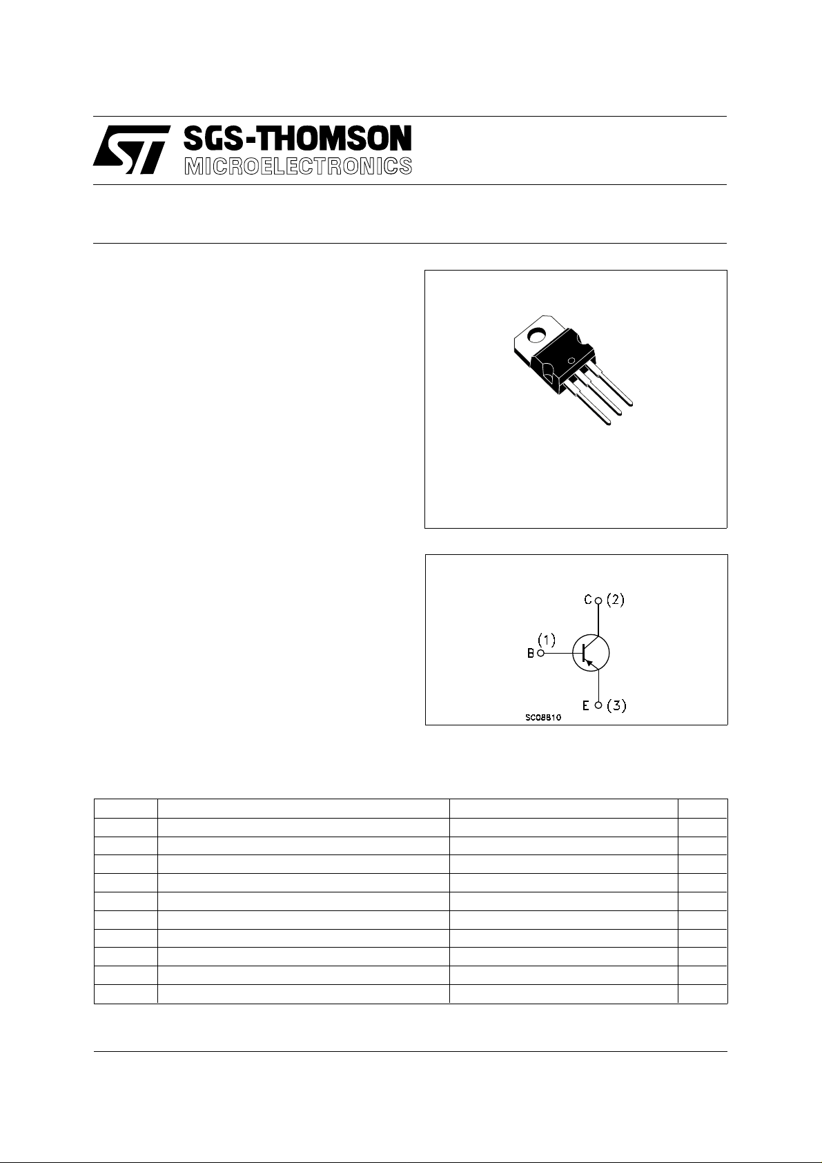
TO-220
MJE5852
3
2
1
INTERNAL SCHEMATIC DIAGRAM
ABSOL UT E MAXIMU M RATIN GS
Symbol Parameter Value Unit
V
V
V
I
I
P
T
For PNP type voltage and current values are negative.
Collector-Emitter Voltage (VBE = 0) 450 V
CES
Collector-Emitter Voltage (IB = 0) 400 V
CEO
Emitter-Base Voltage (IC = 0) 7 V
EBO
Collector Current 8 A
I
C
Collector Peak Current (tp < 5ms) 16 A
CM
Base Current 4 A
I
B
Base Peak Current (tp < 5ms) 8 A
BM
Total Dissipation at Tc ≤ 25 oC80W
tot
Storage Temperature -65 to 150
stg
Max. Operating Junction Temperature 150
T
j
o
C
o
C
1/4
MJE5852
THERMAL DATA
R
thj-case
R
thj-amb
Thermal Resistance Junction-case Max
Thermal Resistance Junction-ambient Max
1.56
62.5
o
C/W
o
C/W
ELECTRICAL CHAR ACTERISTICS (T
= 25 oC unless otherwise specified)
case
Symbol Parameter Test Conditions Min. Typ. Max. Unit
I
CES
I
EBO
V
CEO(sus)
Collector Cut-off
Current (V
= -1.5V)
BE
Emitter Cut-off Current
(I
= 0)
C
∗ Collector-Emitter
= 450 V 500 µA
V
CE
= 6 V 1 mA
V
EB
= 10 mA 400 V
I
C
Sustaining Voltage
(I
=0)
B
V
CE(sat)
V
BE(sat)
∗ Collector-Emitter
Saturation Voltage
∗ Base-Emitter
IC = 4 A IB = 1 A
I
= 8 A IB = 3 A
C
2
5
IC = 4 A IB = 1 A 1.5 V
Saturation Voltage
h
∗ DC Current Gain IC = 2 A VCE = 5 V
FE
I
= 5 A VCE = 5 V
C
15
5
RESISTIVE LOAD
t
∗ Pulsed: Pulse duration = 300 µs, duty cycle 1.5 %
For PNP type voltage and current values are negative.
s
t
f
Storage Time
Fall Time
I
= 4 A VCC = 250 V
C
I
= -IB2 = 1 A tp = 40 µs
B1
2
0.5
V
V
µs
µs
2/4
 Loading...