

SGS Thomson Microelectronics MJE182, MJE172 Datasheet
MJE172
®
MJE182
COMPLEMENTARY SILICON POWER TRANSISTORS
■ SGS-THOMS O N PREF ERRE D SA LES TYP E S
■ COMPLEMEN TA RY PNP - NPN DEVI CES
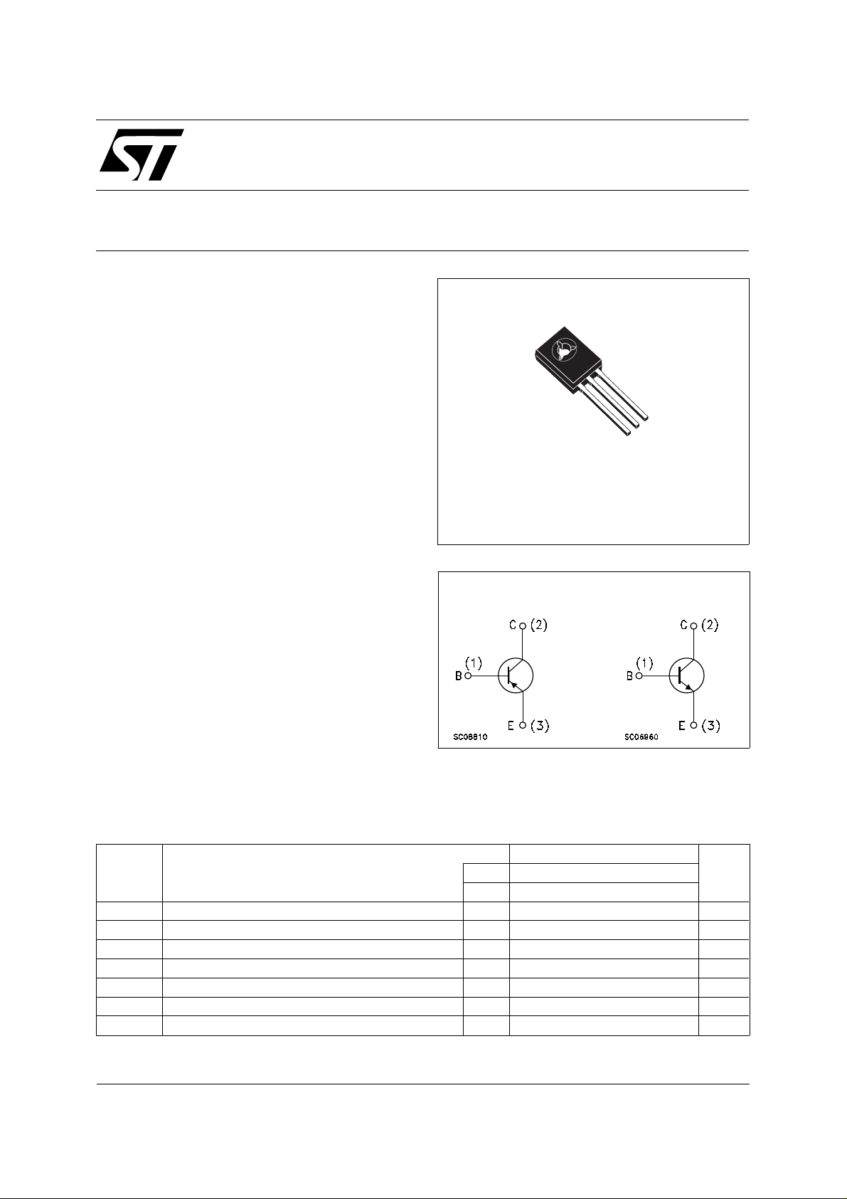
DESCRIPTION
The MJE172 (PNP type) and MJE182 (NPN type)
are silicon epitaxial planar, complementary
transistors in Jedec SOT-32 plastic package, they
are designed for low power audio amplifier and
low current, high speed switching applications.
SOT-32
1
2
3
INTERNAL SCHEMATIC DIAGRAM
ABSOLUT E MAXIMUM RATI NG S
Symbol Parameter Value Unit
NPN MJE182
PNP MJE172
V
V
V
I
P
Collector-Emitter Voltage (IB = 0) 80 80 V
CEO
Collector-Base Voltage (IE = 0) 100 100 V
CBO
Base-Emitter Voltage (IC = 0) 7 7 V
EBO
Collector Current 3 3 A
I
C
Collector Peak Current 6 6 A
CM
Base Current 1 1 A
I
B
Total Power Dissipation at T
tot
≤ 25 oC 12.5 12.5 W
case
September 1998
1/4
MJE172 - MJE182
THERMAL DATA
R
thj-amb
R
thj-case
Thermal Resistance Junction-ambient Max
Thermal Resistance Junction-case Max
83.4
10
o
C/W
o
C/W
ELECTRICAL CHARACTERISTICS (T
= 25 oC unless otherwise specified)
case
Symbol Parameter Test Conditions Min. Typ. Max. Unit
I
CBO
I
EBO
V
CEO(sus)
Collector Cut-off
Current (I
= 0)
E
Emitter Cut-off Current
(I
= 0)
C
∗ Collector-Emitter
= rated V
V
CB
T
CASE =
= 7 V 0.1 µA
V
EB
CBO
150oC
0.1
0.1
IC = 10 mA 80 V
Sustaining Voltage
V
∗ Collector-Emitter
CE(sat)
Saturation Voltage
V
∗ Base-Emitter on
BE(sat)
Voltage
VBE∗ Base-Emitter on
IC = 0.5 A IB = 50 mA
I
= 1.5 A IB = 0.15 A
C
I
= 3 A IB = 0.6 A
C
IC = 1.5 A IB = 0.15 A
I
= 3 A IB = 0.6 A
C
IC = 0.5 A VCE = 1 V 1.2 V
0.3
0.9
1.7
1.5
2
Voltage
h
f
DC Current Gain IC = 0.1 A VCE = 1 V
FE
Transistor Frequency IC = 0.1 A VCE = 10 V
T
I
= 0.5 A VCE = 1 V
C
I
= 1.5 A VCE = 1 V
C
50
250
30
12
50 MHz
f = 10 MHz
C
CBO
Collector-base
Capacitance
∗ Pulsed: Pulse duration = 300µs, duty cycle ≤ 1.5%
For PNP type voltage and current values are negative.
VCB = 10 V IE = 0 f = 0.1MHz
for MJE172
for MJE182
60
40
µA
mA
V
V
V
V
pF
pF
2/4
 Loading...