

1/32
PRELIMINARY DATA
October 2003
This is preliminary information on a new product now in development or undergoing evaluation. Details are subject to change without notice.
M69AR024B
16 Mbit (1M x16) 1.8V Supply, Asynchronous PSRAM
FEATURES SUMMARY
■ SUPPLY VOLTAG E: 1.7 to 1.95V
■ ACCESS TIME: 70ns, 80ns
■ LOW STANDBY CURRENT: 100µA
■ DEEP POWER DOWN CURRENT: 10µA
■ COMPATIBLE WITH STANDARD LPSRAM
■ TRI-STATE COMMON I/O
Figure 1. Packages
FBGA
TFBGA48 (ZB)
6x8mm

M69AR024B
2/32
TABLE OF CONTENTS
SUMMARY DESCRIPTION . . . . . . . . . . . . . . . . . . . . . . . . . . . . . . . . . . . . . . . . . . . . . . . . . . . . . . . . . . 4
Figure 2. Logic Diagram . . . . . . . . . . . . . . . . . . . . . . . . . . . . . . . . . . . . . . . . . . . . . . . . . . . . . . . . . . 4
Table 1. Signal Names . . . . . . . . . . . . . . . . . . . . . . . . . . . . . . . . . . . . . . . . . . . . . . . . . . . . . . . . . . . 4
Figure 3. TFBGA Connections (Top view through package). . . . . . . . . . . . . . . . . . . . . . . . . . . . . . . 5
Figure 4. Block Diagram . . . . . . . . . . . . . . . . . . . . . . . . . . . . . . . . . . . . . . . . . . . . . . . . . . . . . . . . . . 7
SIGNAL DESCRIPTIONS . . . . . . . . . . . . . . . . . . . . . . . . . . . . . . . . . . . . . . . . . . . . . . . . . . . . . . . . . . . 6
Table 2. Operating Modes. . . . . . . . . . . . . . . . . . . . . . . . . . . . . . . . . . . . . . . . . . . . . . . . . . . . . . . . . 8
OPERATION. . . . . . . . . . . . . . . . . . . . . . . . . . . . . . . . . . . . . . . . . . . . . . . . . . . . . . . . . . . . . . . . . . . . . . 9
Power On Sequence . . . . . . . . . . . . . . . . . . . . . . . . . . . . . . . . . . . . . . . . . . . . . . . . . . . . . . . . . . . . 9
Write Mode. . . . . . . . . . . . . . . . . . . . . . . . . . . . . . . . . . . . . . . . . . . . . . . . . . . . . . . . . . . . . . . . . . . . 9
Standby Mode . . . . . . . . . . . . . . . . . . . . . . . . . . . . . . . . . . . . . . . . . . . . . . . . . . . . . . . . . . . . . . . . . 9
Deep Power-down Mode. . . . . . . . . . . . . . . . . . . . . . . . . . . . . . . . . . . . . . . . . . . . . . . . . . . . . . . . . 9
MAXIMUM RATING . . . . . . . . . . . . . . . . . . . . . . . . . . . . . . . . . . . . . . . . . . . . . . . . . . . . . . . . . . . . . . . 10
Table 3. Absolute Maximum Ratings . . . . . . . . . . . . . . . . . . . . . . . . . . . . . . . . . . . . . . . . . . . . . . . .10
DC and AC PARAMETERS. . . . . . . . . . . . . . . . . . . . . . . . . . . . . . . . . . . . . . . . . . . . . . . . . . . . . . . . . 1 1
Table 4. Operating and AC Measurement Conditions. . . . . . . . . . . . . . . . . . . . . . . . . . . . . . . . . . . 11
Figure 5. AC Measurement I/O Waveform . . . . . . . . . . . . . . . . . . . . . . . . . . . . . . . . . . . . . . . . . . . 11
Figure 6. AC Measurement Load Circuit . . . . . . . . . . . . . . . . . . . . . . . . . . . . . . . . . . . . . . . . . . . . . 11
Table 5. Capacitance . . . . . . . . . . . . . . . . . . . . . . . . . . . . . . . . . . . . . . . . . . . . . . . . . . . . . . . . . . . . 12
Table 6. DC Characteristics. . . . . . . . . . . . . . . . . . . . . . . . . . . . . . . . . . . . . . . . . . . . . . . . . . . . . . . 12
Table 7. Read Mode AC Characteristics . . . . . . . . . . . . . . . . . . . . . . . . . . . . . . . . . . . . . . . . . . . . . 13
Figure 7. Address Controlled, Read Mode AC Waveforms. . . . . . . . . . . . . . . . . . . . . . . . . . . . . . . 14
Figure 8. Address and Output Enable Controlled, Read Mode AC Waveform s . . . . . . . . . . . . . . . 14
Figure 9. LB/UB Controlled, Read Mode AC Waveforms . . . . . . . . . . . . . . . . . . . . . . . . . . . . . . . . 15
Table 8. Write Mode AC Characteristics . . . . . . . . . . . . . . . . . . . . . . . . . . . . . . . . . . . . . . . . . . . . . 16
Figure 10. Write Enable Controlled, Write AC Waveforms . . . . . . . . . . . . . . . . . . . . . . . . . . . . . . . 17
Figure 11. Write Enable Controlled, Write AC Waveforms . . . . . . . . . . . . . . . . . . . . . . . . . . . . . . . 18
Figure 12. Write Enable and UB/LB Controlled, Write AC Waveforms 1 . . . . . . . . . . . . . . . . . . . . 19
Figure 13. Write Enable and UB/LB Controlled, Write AC Waveforms 2 . . . . . . . . . . . . . . . . . . . . 20
Figure 14. Write Enable and UB/LB Controlled, Write AC Waveforms 3 . . . . . . . . . . . . . . . . . . . . 21
Figure 15. Write Enable and UB/LB Controlled, Write AC Waveforms 4 . . . . . . . . . . . . . . . . . . . . 22
Figure 16. Chip Enable Controlled, Read and Write Mode AC Waveforms . . . . . . . . . . . . . . . . . . 23
Figure 17. Chip Enable, Write Enable, Output Enable Controlled, Read and Write Mode AC
Waveforms . . . . . . . . . . . . . . . . . . . . . . . . . . . . . . . . . . . . . . . . . . . . . . . . . . . . . . . . . . . . . . . . . . . 24
Figure 18. Output Enable and Write Enable Controlled, Read and Write Mode AC Waveforms . . 25
Figure 19. Output Enable, Write Enable and UB/LB Controlled, Read and Write Mode AC Waveforms
26
Table 9. Standby Mode AC Characteristics . . . . . . . . . . . . . . . . . . . . . . . . . . . . . . . . . . . . . . . . . . . 27

3/32
M69AR024B
Figure 20. Power Down Mode AC Waveforms . . . . . . . . . . . . . . . . . . . . . . . . . . . . . . . . . . . . . . . . 27
Figure 21. Power-Up Mode AC Waveforms . . . . . . . . . . . . . . . . . . . . . . . . . . . . . . . . . . . . . . . . . . 28
Figure 22. Standby Mode Entry AC Waveforms, After Read . . . . . . . . . . . . . . . . . . . . . . . . . . . . . 28
PACKAGE MECHANICAL. . . . . . . . . . . . . . . . . . . . . . . . . . . . . . . . . . . . . . . . . . . . . . . . . . . . . . . . . . 29
TFBGA48 6x8mm - 6x8 active ball array, 0.75 mm pitch, Package Outline, Bo ttom View . . . . . . . 29
TFBGA48 6x8mm - 6x8 active ball array, 0.75 mm pitch, Package Mechanical Data . . . . . . . . . . 29
PART NUMBERING. . . . . . . . . . . . . . . . . . . . . . . . . . . . . . . . . . . . . . . . . . . . . . . . . . . . . . . . . . . . . . . 30
Table 11. Ordering Information Scheme . . . . . . . . . . . . . . . . . . . . . . . . . . . . . . . . . . . . . . . . . . . . . 30
REVISION HISTORY . . . . . . . . . . . . . . . . . . . . . . . . . . . . . . . . . . . . . . . . . . . . . . . . . . . . . . . . . . . . . . 31
Table 12. Document Revision History. . . . . . . . . . . . . . . . . . . . . . . . . . . . . . . . . . . . . . . . . . . . . . .31
M69AR024B
4/32
SUMMARY DESCRIPTION
The M69AR024B is a 16 Mbit (16,777,216 bit)
CMOS memory, organized as 1,024,576 words by
16 bits, and is suppl ied by a sing le 1. 7V to 1.95V
supply voltage range.
M69AR024B is a member of STMicroelectronics
1T/1C (one transistor per cell) memory family.
These devices are manufactured using dynamic
random access memory cells, to minimize the cell
size, and maximize the amount of memory that
can be implemented in a given area.
However, through the use of internal control logic,
the device is fully static in its operation, requiring
no external clocks or timing strobes, and has a
standard Asynchronous SRAM Interface.
The internal control logic of the M69AR0 24B handles the periodic refresh cycle, automatically, and
without user involvement.
Write cycles can be performed on a single byte by
using Upper Byte Enable (UB
) and Lower Byte En-
able (LB
).
The device can be put into standby mode using
Chip Enable (E1
) or in deep power down mode by
using Chip Enable (E2).
Power-Down mode achieves a very low current
consumption by halting all the internal activities.
Since the refresh circuitry is halted, the duration of
the power-down should be less than the maximum
period for refresh, if the user has not finished with
the data contents of the memory.
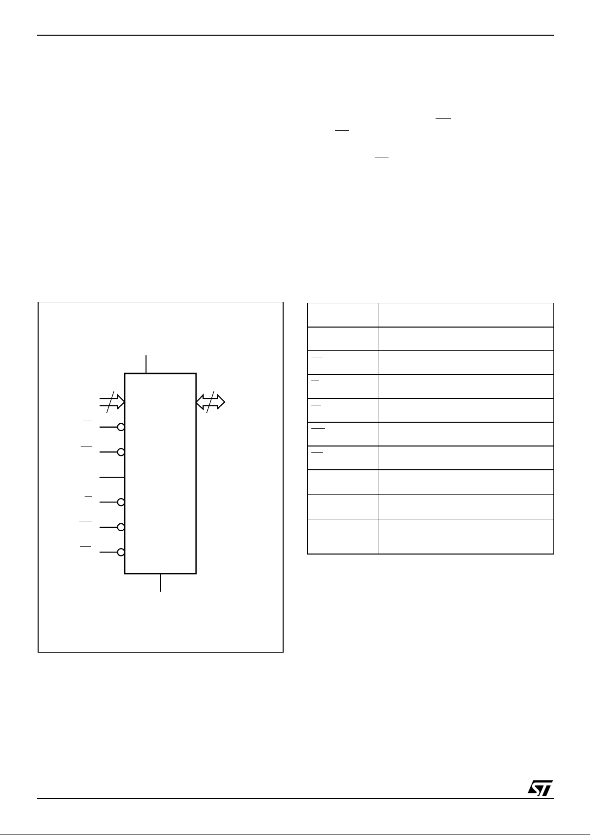
Figure 2. Logic Diagram Table 1. Signal Names
AI07260
20
A0-A19
W
DQ0-DQ15
V
CC
M69AR024B
G
16
E1
UB
LB
V
SS
E2
A0-A19 Address Inputs
DQ0-DQ15 Data Input/Output
E1
, E2 Chip Enable
G
Output Enable
W
Write Enable
UB
Upper Byte Enable Input
LB
Lower Byte Enable Input
V
CC
Supply Voltage
V
SS
Ground
NC
Not Connected
(no internal connection)
5/32
M69AR024B
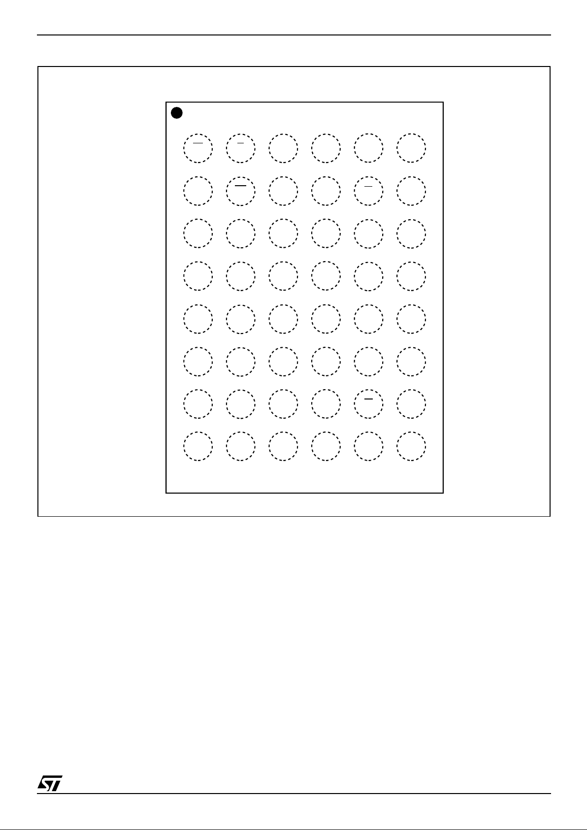
Figure 3. TFBGA Connections (Top view through package)
AI05861b
A
654321
E
B
F
A1
A0G
LB
A17
DQ7WA12
NCA11A8A18
DQ0A3
A6A5
A4 E1
A10
A9
A13
A7
A2 E2
C
DQ4
D
DQ5
A14
A15
G
H
DQ11
A19
UB
DQ10
DQ12
DQ13
V
SS
DQ15
DQ8
DQ9
DQ14
DQ3
DQ2DQ1
V
CC
V
CC
NC V
SS
DQ6
A16

M69AR024B
6/32
SIGNAL DESCRIPTIONS
See Figure 2, Logic Diagram, and Table 1, Sign al
Names, for a brief overview of the signals connected to this device.
Address Inputs (A0-A19). The Address Inputs
select the cell s in the memory arra y to access during Read and Write operations.
Data Inputs/Outputs (DQ8-DQ15). The Upper
Byte Data Inputs/Outputs carry the data to or from
the upper part of the selected address during a
Write or Read operation, when Upper Byte Enable
(UB
) is driven Low.
Data Inputs/Outputs (DQ0-DQ7). The Lower
Byte Data Inputs/Outputs carry the data to or from
the lower part of the selected address during a
Write or Read operation, when Lower Byte Enable
(LB
) is driven Low.
Chip Enable (E1
). When asserted (Low), the
Chip Enab le, E1
, activates the memory state machine, address buffers and decoders, allowing
Read and Write operations to be performed. When
de-asserted (High), all other pins are ignored, and
the device is put, automatically, in low-power
Standby mode.
Chip Enable (E2). The Chip Enable, E2, puts the
device in Deep Power-down mode when it
is driven Low. This is the lowest power mode.
Output Enable (G
). The Output Ena ble, G, pro-
vides a high speed tri-state control, allowing fast
read/write cycles to be achieved with the common
I/O data bus.
Write Enable (W
). The Write Enable, W, controls
the Bus Write operation of the memory’s Command Interface.
Upper Byte Enab le (UB
). The Upper Byte En-
able, UB
, gates the data on the Upper Byte Data
Inputs/Outputs (DQ8-DQ15) to or from the upper
part of the selected address during a Write or
Read operation.
Lower Byte Enable (LB
). The Lower Byte En-
able, LB
, gates the data on the Lower Byte Data
Inputs/Outputs (DQ0-DQ7) to or from the lower
part of the selected address during a Write or
Read operation.
V
CC
Supply Voltage. The VCC Supply Voltage
supplies the power for all operations (Read or
Write) and for driving the refresh logic, even when
the device is not being accessed.
Vss Ground. The V
SS
Ground is the reference
for all voltage measurements.
7/32
M69AR024B
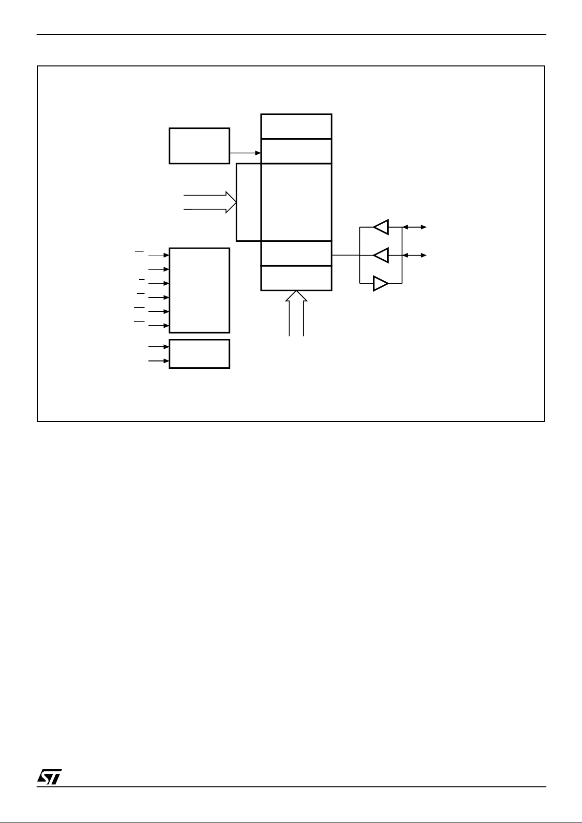
Figure 4. Blo ck Diagram
AI07261b
DYNAMIC
MEMORY
ARRAY
ROW DECODER
COLUMN
DECODER
CONTROL
LOGIC
E1
REFRESH
CONTROLLER
ARBITRATION
LOGIC
INTERNAL
CLOCK
GENERATOR
INPUT/OUTPUT
BUFFER
ADDRESS
UB
E2
G
W
LB
POWER
CONTROLLER
V
CC
V
SS
ADDRESS
DQ0-DQ7
DQ8-DQ15
M69AR024B
8/32
Table 2. Operating Modes
Note: 1. X = VIH or VIL.
2. Should not be kept in this logic condition longer than 1µs. Please contact your local ST sales office for the relaxation of 1µs limitation.
3. Power-d own mode c an be enter ed from the Standby s tate, and al l DQ pins are in High- Z state. I
PD
current and data retention de-
pend on the selection of Power Down Program. See "Power Down Program" for the detail.
4. Can be either VIL or VIH but must be valid before Read or Write.
Operation E2 E1 W G LB UB A0-A19 DQ0-DQ7 DQ8-DQ15
I
CC
Data Re-
tention
Standby
(Deselect)
V
IH
V
IH
X
(1)
X
(1)
X
(1)X (1)
X
(1)
Hi-Z Hi-Z
I
SB
Yes
Output Disabled
V
IH
V
IL
V
IH
V
IH
X
(1)X (1)
Note
(4)
Hi-Z Hi-Z
I
CC
Yes
Output Disabled
(No Read)
(2)
V
IH
V
IL
V
IH
V
IL
V
IH
V
IH
Valid Hi-Z Hi-Z
I
CC
Yes
Upper Byte
Read
(2)
V
IH
V
IL
V
IH
V
IL
V
IH
V
IL
Valid Hi-Z
Output
Valid
I
CC
Yes
Lower Byte
Read
(2)
V
IH
V
IL
V
IH
V
IL
V
IL
V
IH
Valid
Output
Valid
Hi-Z
I
CC
Yes
Word Read
(2)
V
IH
V
IL
V
IH
V
IL
V
IL
V
IL
Valid
Output
Valid
Output
Valid
I
CC
Yes
No Write
(2)
V
IH
V
IL
V
IL V
IH
V
IH
V
IH
Valid Invalid Invalid
I
CC
Yes
Upper Byte
Write
(2)
V
IH
V
IL
V
IL
V
IH
V
IH
V
IL
Valid Invalid Input Valid
I
CC
Yes
Lower Byte
Write
(2)
V
IH
V
IL
V
IL
V
IH
V
IL
V
IH
Valid Input Valid Invalid
I
CC
Yes
Word Write
(2)
V
IH
V
IL
V
IL
V
IH
V
IL
V
IL
Valid Input Valid Input Valid
I
CC
Yes
Power-down
(3)
V
IL
X
(1)X (1)
X
(1)
X
(1)X (1)
X
(1)
Hi-Z Hi-Z
I
PD
Yes/No

9/32
M69AR024B
OPERATION
Operational modes are determined by device control in puts W
, E1, E2, LB and U B as summarized
in the Operating Modes table (see Table 2).
Power On Se quence
Because the internal control logic of the
M69AR024B needs to be initialized, the following
power-on procedure must be followed before the
memory is used:
– Apply power and wait for V
CC
to stabilize
– Wait 300µs while driving both Chip Enable
signals (E1
and E2) High
Read Mode
The device is in Read mode when:
– Write Enable (W
) is High and
– Output Enable (G
) Low and
– Upper Byte Enable (UB
) or Lower Byte En-
able (LB
) is Low, or both
– the two Chip Enable signals are asserted (E1
is Low, and E2 is High).
The time taken to enter Read mode (t
ELQV
, t
GLQV
or t
BLQV
) depends on which of the above signals
was the last to reach the appropriate level.
Data out (DQ15-DQ0) may be indeterminate
during t
ELQX
, t
GLQX
and t
BLQX
, but data will always
be valid during t
AVQV
.
Write Mode
The device is in Write mode when
– Write Enable (W
) is Low and
– Chip Enable (E1
) is Low and
– Upper Byte Enable (UB
) or Lower Byte En-
able (LB
) is Low, or both
– the two Chip Enable signals are asserted (E1
is Low, and E2 is High).
The Write cycle begins just after the event (the falling edge) that causes the last of these conditions
to become true (t
AVWL
or t
AVEL
or t
AVBL
).
The Write cycle is terminated by the earlier of a rising edge on Write Enable (W
) or Chip Enable (E1).
If the device is in Write mode (Chip Enable (E1
) is
Low, Output Enable (G
) is Low, Upp er Byte En-
able (UB
) or Lower Byte Enable (LB) is Low), then
Write Enable (W
) will return the outputs to high im-
pedance within t
WLQZ
of its falling edge. Care must
be taken to avoid bus contention in this type of operation. Data input must be valid for t
DVWH
before
the rising edge of Wr ite Enable (W
), or for t
DVEH
before the rising edge of Chip Enable (E1), whichever occurs first, and remain valid for t
WHDX
, t
EHDX
Standby Mode
The device is in Standby mode when:
– Chip Enable (E1
) is High and
– Chip Enable (E2) is High
The input/output buffers and t he decoding/c ontrol
logic are switched off, but the dynamic array continues to be refreshed. In this mode, the me mory
current consumption, I
SB
, is reduced, and the data
remains valid.
Deep Power-down Mode
The device is in Deep Power-down mode when:
– Chip Enable (E2) is Low
M69AR024B
10/32
MAXIMUM RA TING
Stressing the de vice above the rating l isted in t he
“Absolute Maximum Ratings" table may cause
permanent damage to the device. These are
stress ratings only and operation of t he device at
these or any other conditions above those indicat-
ed in the Operating sections of this specification is
not implied. Exposure to Abs olute M aximum Ra ting conditions for extended periods may affect device r eliab ilit y.
Table 3. Absolute Maximum Ratings
Note: 1. The mi nimum DC voltage on input or I/O pi ns is –0.3 V. During voltage transi tions, inputs may und ershoot V
SS
by 1.0V f or periods
of up to 5ns.
2. The maxim um DC volta ge on inpu t and I/O pins is V
CC
+0.2V. During voltage transitions, inputs may overshoot VCC by 1.0V fo r
periods of up to 5ns.
Symbol Parameter Min Max Unit
I
O
Output Current –50 50 mA
T
A
Ambient Operating Temperature –25 85 °C
T
STG
Storage Temperature –55 125 °C
V
CC
Core Supply Voltage –0.2 3.3 V
V
IO
(1,2)
Input or Output Voltage –0.2 3.3 V

11/32
M69AR024B
DC AND AC PARAMETERS
This section summarizes t he operating and measurement conditions, as well as the DC and AC
characteristics of the device. The parameters in
the following DC and AC Characteristic tables are
derived from tests performed unde r the Measure-
ment Conditions listed in t he relevant tables. Designers should check that the operating conditions
in their projects match the measurement conditions when using the quoted parameters.
Table 4. Operating and AC Measuremen t Conditions
Note: 1. All vol tages are referenced to VSS.
Figure 5. AC Measurement I/O Waveform Figure 6. AC Measurement Load Circuit
Parameter
M69AR024B
Unit
Min Max
V
CC
Supply Voltage
1
1.7 1.95 V
Ambient Operating Temperature –25 85 °C
Load Capacitanc e (C
L
)
50 pF
Output Circuit Protection Resistance (R
1
)
50
Ω
Input Pulse Voltages
0 to V
CC
V
Input and Output Timing Ref. Voltages
V
CC
/2
V
Output Transition Timing Ref. Voltages
V
RL
= 0.3VCC; VRH = 0.7V
CC
V
AI04831
V
CC
I/O Timing Reference Voltage
0V
VCC/2
V
CC
Output Timing Reference Voltage
0V
0.7V
CC
0.3V
CC
AI07222b
VCC/2
OUT
CL includes JIG capacitance
DEVICE
UNDER
TEST
C
L
R
1

M69AR024B
12/32
Table 5. Capacitance
Note: 1. Sampled only, not 100% tested.
2. Outputs deselected .
Table 6. DC Characteristics
Note: 1. The max imum D C voltage on input an d I/O pin s is VCC+0.2V. During voltage transitions, inputs may overshoot VCC by 1.0V fo r
periods of up to 5ns.
2. The mini m um DC volta ge on input or I/O pins is –0.3V. During voltage transiti ons, inputs may under shoot V
SS
by 1.0V f or periods
of up to 5ns.
Symbol
Parameter
(1,2)
Test
Condition
Min Max Unit
C
IN
Input Capacitance on all pins (except DQ)
V
IN
= 0V
5pF
C
OUT
(2)
Output Capacitance
V
OUT
= 0V
8pF
Symbol Parameter Test Condition Min Max Unit
I
CC1
VCC Active Current
V
CC
= 1.95V,
V
IN
= VIH or VIL,
E1
= VIL and E2 = VIH,
I
OUT
= 0mA
t
AVAV
Read /
t
AVAV
Write =
minimum
15 mA
I
CC2
t
AVAV
Read /
t
AVAV
Write =
maximum
3mA
I
LI
Input Leakage Current
0V ≤ V
IN
≤ V
CC
–1 1 µA
I
LO
Output Leakage Current
0V
≤
V
OUT
≤ V
CC
–1 1 µA
I
PD
Deep Power Down Current
V
CC
= 1.95V,
E1
≥ V
CC
–0.2V or E1 ≤ VIL,
V
IN
≥ V
CC
–0.2V or VIN ≤ 0.2V
10 µA
I
SB
Standby Supply Current
CMOS
V
CC
= 1.95V,
E1
= E2 ≥ V
CC
–0.3V,
I
OUT
= 0mA
100 µA
V
IH
(1)
Input High Voltage
0.8V
CC
V
CC
+ 0.2
V
V
IL
(2)
Input Low Voltage –0.2 0.4 V
V
OH
Output High Voltage
I
OH
= –0.1mA V
CC
– 0.2
V
V
OL
Output Low Voltage
I
OL
= 0.1mA
0.2 V

13/32
M69AR024B
Table 7. Read Mode AC Characteristics
Note: 1. Maximum value is applicable if E1 is kept at Low withou t change of address inp ut of A3 to A19 . If needed by sy stem oper ation,
please contact local ST sales offic e f or the relaxat i on of 1µs limitation.
2. Address should not be c hanged withi n tAVAX(m i n).
3. The output load 50pF with 50Ω termin ation to V
CC
*0.5 V.
4. The output load C
L
= 5pF wi t h out any other l oa d.
5. Applicable to A3 to A1 9 when E
1 is kept at Low.
6. Applicabl e only to A0, A1 and A2 when E
1 is kept at Lo w f or the page address acce ss.
7. In case Page Re ad Cyc le is cont inu ed with k eep ing E
1 stays Low , E 1 mus t be b ro ught t o Hi gh wi thin 4µs . In othe r w ords, Pag e
Read Cyc l e m ust be closed within 4µs.
8. Applicabl e when at least two of addr ess inputs among applic abl e are switc hed from previous state.
9. tAVAX(min) must be satisfied.
Symbol Alt. Parameter
M69AR024B
Unit-70 -80
Min Max Min Max
t
AVAX
(1,2)
t
RC
Address Valid Time 80 1000 80 1000 ns
t
AVEL
t
ASC
Address Valid to Chip Enable Low –5 –5 ns
t
AVGL
t
ASO
Address Valid to Output Enable Low 10 10 ns
t
AVQV
(3,5)
t
AA
Address Valid to Output Valid 70 80 ns
t
AXAV
(5,8)
t
AX
Address Invalid Time 10 10 ns
t
AXQX
(3)
t
OH
Data hold from address change 10 10 ns
t
BHQX
(3)
t
OH
Upper/Lower Byte Enable High to Output Transition 10 10 ns
t
BHQZ
(4)
t
BHZ
Upper/Lower Byte Enable High to Output Hi-Z 20 20 ns
t
BLQV
(3)
t
BA
Upper/Lower Byte Enable Low to Output Valid 70 80 ns
t
BLQX
(4)
t
BLZ
Upper/Lower Byte Enable Low to Output Transition 5 5 ns
t
EHAX
(9)
t
CHAH
Chip Enable High to Address Invalid –5 –5 ns
t
EHEL
t
CP
Chip Enable High to Chip Enable Low 15 15 ns
t
EHQX
(3)
t
OH
Chip Enable High to Output Transition 10 10 ns
t
EHQZ
(4)
t
CHZ
Chip Enable High to Output Hi-Z 20 20 ns
t
ELAX
(1,2)
t
RC
Read Cycle Time 80 1000 80 1000 ns
t
ELEH
(1,2)
t
RC
Read Cycle Time 80 1000 80 1000 ns
t
ELQV
(3)
t
CE
Chip Enable Low to Output Valid 70 80 ns
t
ELQX
(4)
t
CLZ
Chip Enable Low to Output Transition 10 10 ns
t
GHAX
t
OHAH
Output Enable High to Address Invalid –5 –5 ns
t
GHQX
(3)
t
OH
Output Data Hold Time 10 10 ns
t
GHQZ
(4)
t
OHZ
Output Enable High to Output Hi-Z 20 20 ns
t
GLQV
(3)
t
OE
Output Enable Low to Output Valid 45 45 ns
t
GLQX
(4)
t
OLZ
Output Enable Low to Output Transition 5 5 ns

M69AR024B
14/32
Figure 7. Address Controlled, Read Mode AC Waveforms
Note: E2 = High, W = High.
Figure 8. Address and Output Enable Controlled, Read Mode AC Waveforms
Note: W = High, E2 = High.
AI04819C
t
ELQV
VALID DATA OUTPUT
ADDRESS
E1
DQ
(Output)
G
t
EHQX
t
ELEH
t
ELQX
t
EHAX
t
EHEL
ADDRESS VALID
t
AVEL
t
AVEL
t
GHQ X
t
EHQX
t
BHQX
LB / UB
t
GLQV
t
BLQV
t
BLQX
t
G LQX
AI05863c
t
AVQV
VALID DATA OUTPUT
ADDRESS
E1
DQ
(Output)
LB / UB
t
G HQ Z
t
GLQV
t
AVAX
t
G LQX
ADDRESS VALID
VALID DATA OUTPUT
ADDRESS VALID
t
AVAX
t
AXQX
t
G HQX
G
t
AxAV
t
AXAV
Low
t
AVQV
t
AxAV

15/32
M69AR024B
Figure 9. LB/UB Controlled, Read Mode AC Waveforms
Note: E1 = Low, E2 = High, G = Lo w, W = High.
AI07497b
t
AVQV
VALID DATA
OUTPUT
ADDRESS
DQ0-7
(Output)
UB
t
BHQZ
t
BLQV
t
AVAX
t
BLQX
ADDRESS VALID
VALID DATA
OUTPUT
t
BHQZ
t
BHQX
LB
t
AXAV
t
BLQV
t
AxAV
DQ8-15
(Output)
t
BLQX
t
BLQV
t
BLQX
t
BHQX
t
BHQZ
t
BHQX
VALID DATA OUTPUT

M69AR024B
16/32
Table 8. Write Mode AC Characteristics
Note: 1. Maximum value is applicable if E1 is kept at Low without any addr ess change. If needed by syst em operation, please conta ct your
local ST re presentative for relaxation of the 1000ns limi ta tion.
2. Minimum value must be equal to or greater than the sum of write pulse (tELEH, tWLWH or tBLBH) and write recovery time (tWRC,
tWR or tBR).
3. Write pulse is defined from the falling edge of E1
, W, or LB/UB, whichever occurs last.
4. Write recovery is defi ned from Wri t e pul se is defined from the rising edge of E 1
, W, or LB/U B, whichever occurs first.
5. Applicabl e to any addr ess change when E1
stays Low.
6. If G
is Low after mi ni m um tGHEL, the read cycl e is in i tiated. In other words, G must be brought High within 5ns after E1 is brought
Low. On ce the read cycl e i s in i t i ated, new wr i te pulse should be input aft er mini m um Read Cycle T i m e i s met.
7. If G
is Low after new address in put, the read cycle is initiat ed. In other words, G must be brough t Hi gh at the sam e time or before
new addres s valid. Once the read cycle is initiated, new wri t e pulse shoul d be input aft er m i nimum Rea d Cycle Time is met.
Symbol Alt. Parameter
M69AR024B
Unit-70, -80
Min Max
t
AVAX
(1,2)
t
WC
Write Cycle Time 80 1000 ns
t
AVBL
(2)
t
AS
Address Valid to LB, UB Low 0 ns
t
AVEL
(2)
t
AS
Address Valid to Chip Enable Low 0 ns
t
AVWL
(2)
t
AS
Address Valid to Write Enable Low 0 ns
t
AXAV
(5)
t
AXW
Address Invalid Time for Write 10 ns
t
BHAX
(4)
t
BR
LB, UB High to Address Transition 15 1000 ns
t
BHDX
t
DH
LB, UB High to Input Transition 0 ns
t
BLBH
(3)
t
BW
LB, UB Low to LB, UB High 75 ns
t
BLBH2
t
BWO
LB, UB Low to LB, UB High, Pulse Overlap 20 ns
t
BLWH
(3)
t
BW
LB, UB Low to Write Enable High 75 ns
t
DVBH
t
DS
Input Valid to LB, UB High 30 ns
t
DVEH
t
DS
Input Valid to Chip Enable High 30 ns
t
DVWH
t
DS
Input Valid to Write Enable High 30 ns
t
EHAX
(4)
t
WRC
Chip Enable High to Address Transition 15 ns
t
EHDX
t
DH
Chip Enable High to Input Transition 0 ns
t
EHEL
t
CP
Chip Enable High to Chip Enable Low 15 ns
t
ELAX
(1,2)
t
WC
Write Cycle Time 80 1000 ns
t
ELEH
(3)
t
CW
Chip Enable Low to Chip Enable High 75 ns
t
GHAV
(7)
t
OES
Output Enable High to Address Valid 0 ns
t
GHEL
(6)
t
OHCL
Output Enable High to Chip Enable Low –5 ns
t
WHAX
(4)
t
WR
Write Enable High to Address Transition 15 1000 ns
t
WHDX
t
DH
Write Enable High to Input Transition 0 ns
t
WLBH
(3)
t
WP
Write Enable Low to LB, UB High 65 ns
t
WLWH
(3)
t
WP
Write Enable Low to Write Enable High 65 1000 ns

17/32
M69AR024B
Figure 10. Write Enable Controlled, Write AC Waveforms
Note: E2 = Hi gh.
AI05865c
t
AVEL
VALID DATA INPUT
ADDRESS
E1
DQ
(Input)
W
t
EHDX,WHDX,BHDX
t
DVEH,DVWH,DVBH
t
ELAX
t
EHAX
t
WLWH
t
ELEH
LB, UB
t
AVBL
t
BLBH
ADDRESS VALID
t
AVEL
t
AVWL
t
BHAX
G
t
G HEL
t
AVWL
t
AVBL
t
WHAX

M69AR024B
18/32
Figure 11. Write Enable Controlled, Write AC Waveforms
Note: E2 = Hi gh.
AI05866c
t
AVWL
ADDRESS
W
E1
t
A VAX
t
WHAX
t
WLWH
LB, UB
ADDRESS VALID
t
AVWL
t
WHAX
t
WLWH
VALID DATA INPUT
DQ
(Input)
t
W HDX
t
DVWH
G
t
GHAV
t
G HQZ
t
AVAX
t
AXAV
VALID DATA INPUT
t
W HDX
t
DVWH
Low
ADDRESS VALID

19/32
M69AR024B
Figure 12. Write Enable and UB/LB Controlled, Write AC Waveforms 1
Note: E2 = Hi gh.
AI07492b
t
AVWL
ADDRESS
W
E1
t
AVAX
t
BHAX
t
WLBH
LB
ADDRESS VALID
t
AVWL
t
BHAX
t
WLBH
VALID DATA INPUT
DQ0-7
(Input)
t
BHDX
t
DVBH
UB
t
AVAX
t
AXAV
VALID DATA INPUT
t
BHDX
t
DVBH
Low
ADDRESS VALID
DQ8-15
(Input)

M69AR024B
20/32
Figure 13. Write Enable and UB/LB Controlled, Write AC Waveforms 2
Note: E2 = Hi gh.
AI07491b
t
AVBL
ADDRESS
W
E1
t
AVAX
t
WHAX
t
BLWH
LB
ADDRESS VALID
t
AVBL
t
AXAV
t
WHAX
t
BLWH
VALID DATA INPUT
DQ0-7
(Input)
t
WHDX
t
DVWH
UB
t
AVAX
t
AXAV
VALID DATA INPUT
t
W HDX
t
DVWH
Low
ADDRESS VALID
t
AXAV
DQ8-15
(Input)

21/32
M69AR024B
Figure 14. Write Enable and UB/LB Controlled, Write AC Waveforms 3
Note: E2 = Hi gh.
AI07490b
t
AVBL
ADDRESS
W
E1
t
AVAX
t
BHAX
t
BLBH
LB
ADDRESS VALID
t
AVBL
t
AXAV
t
BHAX
t
BLBH
VALID DATA INPUT
DQ0-7
(Input)
t
BHDX
t
DVBH
UB
t
AVAX
t
AXAV
VALID DATA INPUT
t
BHDX
t
DVBH
Low
ADDRESS VALID
t
AXAV
DQ8-15
(Input)

M69AR024B
22/32
Figure 15. Write Enable and UB/LB Controlled, Write AC Waveforms 4
Note: E2 = Hi gh.
AI07489c
t
AVBL
ADDRESS
W
E1
t
AVAX
t
BHAX
t
BLBH
LB
ADDRESS VALID
t
AVBL
t
AXAV
t
BHAX
t
BLBH
DQ0-7
(Input)
t
BHDX
t
DVBH
UB
t
AVAX
t
AXAV
t
BHDX
t
DVBH
Low
ADDRESS VALID
t
AXAV
DQ8-15
(Input)
t
BHDX
t
DVBH
t
AVBL
t
BHAX
t
BLBH
t
AVBL
t
BHAX
t
BLBH
t
BHDX
t
DVBH
VALID
DATA INPUT
VALID
DATA INPUT
VALID
DATA INPUT
VALID
DATA INPUT
t
BLBH2
t
BLBH2

23/32
M69AR024B
Figure 16. Chip Enable Controlled, Read and Write Mode AC Waveforms
Note: Write address is valid from last falling edge of either E1 or W.
AI07280c
READ DATA OUTPUT
ADDRESS
E1
DQ
W
t
ELAX
t
ELEH
G
t
G HEL
UB, LB
t
EHAX
t
EHEL
WRITE ADDRESS
t
AVEL
t
ELAX(read)
WRITE DATA INPUT
t
DVEH
t
EHQ Z
t
EHQX
t
EHEL
t
ELQV
t
AVEL(read)
READ ADDRESS
t
EHAX
t
EHAX(read)
t
EHDX
t
ELQX
t
EHQX

M69AR024B
24/32
Figure 17. Chip Enable, Write Enable, Output Enable Controlled, Read and Write Mode AC
Waveforms
Note: G can be fixed Low duri ng the wr i te part of a re ad-write-read operation that is under E1 control .
AI07281c
READ DATA OUTPUT
ADDRESS
E1
DQ
W
t
ELAX
t
WLWH
G
t
GHEL
UB, LB
t
GLQV
t
EHAX
t
EHEL
WRITE ADDRESS
t
AVEL
t
ELAX(read)
WRITE DATA INPUT
t
DVWH
t
EHQ Z
t
EHQX
t
EHEL
t
ELQV
t
AVEL(read)
READ ADDRESS
t
WHAX
t
EHAX(read)
t
W HDX
t
GLQX
t
G HQX
READ DATA OUTPUT

25/32
M69AR024B
Figure 18. Output Enable and Writ e E n ab l e Co n trolled, Read and Writ e M o de AC Wavefo rms
Note: E1 can be t i ed Low for a W and G controlled operation.
When E1
is tied Low, the output is exclusively controlled by G.
AI07282c
READ DATA OUTPUT
ADDRESS
E1
DQ
W
t
AVAX
t
WLWH
G
UB, LB
t
GLQV
t
AXAV
WRITE ADDRESS
t
AVWL
t
AVAX(read)
WRITE DATA INPUT
t
DVWH
t
G HQ Z
t
G HQX
t
AVQV
t
AXAV
READ ADDRESS
t
WHAX
t
AXAV
t
W HDX
t
G LQX
t
GHQX
READ DATA OUTPUT
t
GHQ Z
Low
t
AVGL

M69AR024B
26/32
Figure 19. Output E nable, Write Enable and UB/LB Controlled, Read and Write Mode AC Waveforms
Note: E1 can be t i ed Low for a W and G controlled operation.
When E1
is tied Low, the output is exclusively controlled by G.
AI07283c
READ DATA OUTPUT
ADDRESS
E1
DQ
W
t
AVAX
t
BLBH
G
UB, LB
t
BLQV
t
AXAV
WRITE ADDRESS
t
AVBL
t
AVAX(read)
WRITE DATA INPUT
t
DVBH
t
BHQ Z
t
BHQX
t
AVQV
t
AXAV
READ ADDRESS
t
BHAX
t
AXAV
t
BHDX
t
BLQX
t
BHQX
READ DATA OUTPUT
t
BHQZ
Low
t
AVGL

27/32
M69AR024B
Table 9. Standby Mode AC Characteristics
Note: 1. Applica b l e al so to Power-u p.
2. Some dat a m i gh t be writ ten int o an y addres s l ocati on if tEHWL (min ) i s no t satisfied.
3. The Input Transition Time (tτ) at AC testing is 5ns as shown below. If actual tτ is longer than 5ns, it may violate AC specification of
some timing parameters.
Figure 20. Power Down Mode AC Waveforms
Symbol Alt. Parameter
M69AR024B
Unit-70, -80
Min Max
t
CLEX
t
CSP
E2 Low Setup Time for Power Down Entry 10 ns
t
EXCH
t
C2LP
E2 Low Hold Time after Power Down Entry 70 ns
t
EHEV
(1)
t
CHH
E1 High Hold Time following E2 High after PowerDown Exit (Sleep Mode only)
300 µs
t
CHEL
t
CHH
E1 High Hold Time following E2 High after PowerDown Exit (not in Sleep Mode)
300 µs
t
EHCH
t
CHS
E1 High Setup Time following E2 High after
Power-Down Exit
0µs
t
EHGL
t
CHOX
E1 High to G Invalid Time for Standby Entry 10 ns
t
EHWL
(2)
t
CHWX
E1 High to W Invalid Time for Standby Entry 10 ns
t
τ
(3)
t
τ
Input Transition Time 1 25 ns
AI05864b
t
CLEX
E1
Power Down Entry
E2
t
EXCH
t
CHEL
Power Down Mode Power Down Exit
t
EHCH
DQ
High-Z

M69AR024B
28/32
Figure 21. Power-Up Mode AC Waveforms
Figure 22. Standby Mode Entr y AC Waveforms, After Read
Note: E2 = Hi gh.
AI07284b
E1
V
CC
V
CC
(min)
0V
E2
t
EHEV
AI07750b
t
EHGL
E1
G
W
Active (Read) Standby Active (Write) Standby
t
EHWL

29/32
M69AR024B
PACKAGE MECHANICAL
Figure 23. TFBGA48 6x8mm - 6x8 active ball array, 0.75 mm pitch, Package Outline, Bottom View
Note: Drawing is not to scale.
Table 10. TFBGA48 6x8mm - 6x8 active ball array, 0.75 mm pitch, Package Mechanical Data
Symbol
millimeters inches
Typ Min Max Typ Min Max
A 1.200 0.0472
A1 0.260 0.0102
A2 0.900 0.0354
b 0.350 0.450 0.0138 0.0177
D 6.000 5.900 6.100 0.2362 0.2323 0.2402
D1 3.750 – – 0.1476 – –
ddd 0.100 0.0039
E 8.000 7.900 8.100 0.3150 0.3110 0.3189
E1 5.250 – – 0.2067 – –
e 0.750 – – 0.0295 – –
FD 1.125 – – 0.0443 – –
FE 1.375 – – 0.0541 – –
SD 0.375 – – 0.0148 – –
SE 0.375 – – 0.0148 – –
E1E
D1
D
eb
A2
A1
A
BGA-Z26
ddd
FD
FE
SD
SE
e
BALL "A1"

M69AR024B
30/32
PART NUMBERING
Table 11. Ordering Information Scheme
The notation used for the device number is as show n in Table 11. For a list of available option s (speed,
package, etc.) or for further information on any aspect of this device, please contact your nearest STMicroelect ronics Sa l e s Office.
Example: M69AR024 B L 70 ZB 8 T
Device Type
M69 = 1T/1C Memory Cell Architecture
Mode
A = Asynchronous
Operating Voltage
R = 1.7 to 1.95V
Array Organization
024 = 16 Mbit (1M x16)
Option 1
B = 2 Chip Enable
Option 2
L = L-Die
Speed Class
70 = 70 ns
80 = 80 ns
Package
ZB = TFBGA48, 6x8mm, 0.75mm pitch
Operative Temperature
8 = –30 to 85 °C
Shipping Method
T = Tape & Reel Packing

31/32
M69AR024B
REVISION HISTORY
Table 12. Document Revision History
Date Version Revision Details
09-Oct-2002 1.0 First Issue
17-Feb-2003 2.0 Document completely revised
14-Mar-2003 2.1 AC Measurement Load Circuit revised. A19-A3 address line labelling corrected
04-Apr-2003 2.2
Correction to signal description in Write Mode section; tBLQZ,ELQZ,GLQZ renamed
as tBLQX,ELQX,GLQX in Read Mode AC Characteristics; a minor label correction in
a timing diagram; and value of tEXCH(min) changed
04-Jun-2003 2.3
ZH (8x10mm) package removed. Access time changed to 80ns, with many
consequent changes to timing parameters in AC Characteristics tables.
Ambient Operating Temperatures changed.
Some DC Characteristics (and their Test Conditions) changed
17-Jun-2003 2.4 Standby current changed
25-Jul-2003 2.5
Power-on sequence described, and values for t
EHEV
(min) and t
CHEL
(min) revised.
21-Oct-2003 2.6 70ns and 80ns access times offered as two options

M69AR024B
32/32
Informa tion furnished is believed to be ac curate and reliable. However, STMicroelectro ni cs assumes no resp onsibility for the consequence s
of use of such information nor for any infringement of patents or other rights of third parties which may result from its use. No license is granted
by implication or otherwis e under any patent or patent ri ghts of STM i croelectr onics. Specifications mentioned in thi s publicati on are subject
to change without notice. This publication supersedes and replaces all information previously supplied. STMicroelectronics products are not
authoriz ed for use as cri tical comp onents in life support devi ces or systems without express writt en approval of STM i croelect ronics.
The ST logo is registered trade m ark of STMicroelectronics
All other names are th e property of their respec tive owners
© 2003 STMicroelectronics - All Rights Reserved
STMicroelectronics group of companies
Australia - Brazil - Canada - China - F i nl and - France - Germany - Hong Kong -
India - Is rael - Italy - Japan - Malay sia - Malta - M orocco - Sing apore - Spai n - S weden - Switz erland - Un ited Kingdo m - United States.
www.st.com
 Loading...