

SGS Thomson Microelectronics M58BW016DT, M58BW016DB, M58BW016BT, M58BW016BB, M58BW016 Datasheet
1/63May 2003
M58BW016BT, M58BW016BB
M58BW016DT, M58BW016DB
16 Mb i t ( 512Kb x32, B oot Bl oc k, Bur st)
3V Supply Flash Memories
PE4FEATU R ES SUMMA R Y
■ SUPPLY VOLTAGE
–V
DD
= 2.7V to 3. 6V for Program, Erase and
Read
–V
DDQ
= V
DDQIN
= 2.4V to 3.6V for I/O Buffers
–V
PP
= 12V for fast Program (optional)
■ HIGH PERFORMANCE
– Access Time: 80, 90 and 100ns
– 56MHz Effective Zero Wait-State Burst Read
– Synchronous B urst Reads
– Asynchronous Pa ge Reads
■ HARDWARE BLOCK PROTECT ION
–W
P pin Lock Program and Erase
■ SOFTWARE BLOCK PROTECTION
– Tuning Protection to Lock Program and
Erase with 64 b it User Programmable Password (M58BW016B version only)
■ OPTIMIZED for FDI DRIVERS
– Fast Program / Erase susp end latency
time < 6µs
– Comm on Fla sh Interface
■ MEMORY BLOCKS
– 8 Parameters Blocks (Top or Bottom)
– 31 Main Blocks
■ LOW POWER CONSUMPTION
– 5µA Typical Deep Power Down
– 60µA Typic al Standby
– Automatic Standby after Asynchronous Read
■ ELECTRONIC SIGNATURE
– Manufacturer Code: 20h
– Top Device Code M58BW 016xT: 8836h
– Bottom Device Code M58BW 016x B: 8835 h
Figure 1. Packages
BGA
LBGA80 (ZA)
10 x 8 ball array
PQFP80 (T)

M58BW016BT, M58BW016BB, M58BW016D T, M58BW016DB
2/63
TABLE OF CONTENTS
SUMMARY DESCRIPTION. . . . . . . . . . . . . . . . . . . . . . . . . . . . . . . . . . . . . . . . . . . . . . . . . . . . . . . . . . . 6
Figure 2. Logic Diagram . . . . . . . . . . . . . . . . . . . . . . . . . . . . . . . . . . . . . . . . . . . . . . . . . . . . . . . . . 7
Table 1. Signal Names . . . . . . . . . . . . . . . . . . . . . . . . . . . . . . . . . . . . . . . . . . . . . . . . . . . . . . . . . . 7
Figure 3. LBGA Connections (Top view through package) . . . . . . . . . . . . . . . . . . . . . . . . . . . . . . . 8
Figure 4. PQFP Connections (Top view through package). . . . . . . . . . . . . . . . . . . . . . . . . . . . . . . 9
Block Protection . . . . . . . . . . . . . . . . . . . . . . . . . . . . . . . . . . . . . . . . . . . . . . . . . . . . . . . . . . . . . . 10
Tuning Block Protection. . . . . . . . . . . . . . . . . . . . . . . . . . . . . . . . . . . . . . . . . . . . . . . . . . . . . . . . . . 10
Table 2. Top Boot Block Addresses, M58BW016B T, M58BW016DT . . . . . . . . . . . . . . . . . . . . . . 11
Table 3. Bottom Boot Block Addresses, M58BW016B B , M58BW016DB . . . . . . . . . . . . . . . . . . . 12
SIGNAL DESCRIPTIONS . . . . . . . . . . . . . . . . . . . . . . . . . . . . . . . . . . . . . . . . . . . . . . . . . . . . . . . . . . . 13
Address Inputs (A0-A18). . . . . . . . . . . . . . . . . . . . . . . . . . . . . . . . . . . . . . . . . . . . . . . . . . . . . . . . . 13
Data Inputs/Outputs (DQ0-DQ31 ). . . . . . . . . . . . . . . . . . . . . . . . . . . . . . . . . . . . . . . . . . . . . . . . . .13
Chip Enable (E). . . . . . . . . . . . . . . . . . . . . . . . . . . . . . . . . . . . . . . . . . . . . . . . . . . . . . . . . . . . . . . . 13
Output Enable (G). . . . . . . . . . . . . . . . . . . . . . . . . . . . . . . . . . . . . . . . . . . . . . . . . . . . . . . . . . . . . . 13
Output Disable (GD).. . . . . . . . . . . . . . . . . . . . . . . . . . . . . . . . . . . . . . . . . . . . . . . . . . . . . . . . . . . . 13
Write Enable (W). . . . . . . . . . . . . . . . . . . . . . . . . . . . . . . . . . . . . . . . . . . . . . . . . . . . . . . . . . . . . . . 13
Reset/Power-Down (RP). . . . . . . . . . . . . . . . . . . . . . . . . . . . . . . . . . . . . . . . . . . . . . . . . . . . . . . . . 13
Latch Enable (L).. . . . . . . . . . . . . . . . . . . . . . . . . . . . . . . . . . . . . . . . . . . . . . . . . . . . . . . . . . . . . . . 13
Burst Clock (K).. . . . . . . . . . . . . . . . . . . . . . . . . . . . . . . . . . . . . . . . . . . . . . . . . . . . . . . . . . . . . . . . 14
Burst Address Advance (B). . . . . . . . . . . . . . . . . . . . . . . . . . . . . . . . . . . . . . . . . . . . . . . . . . . . . . . 14
Valid Data Ready (R). . . . . . . . . . . . . . . . . . . . . . . . . . . . . . . . . . . . . . . . . . . . . . . . . . . . . . . . . . . . 14
Write Protect (WP). . . . . . . . . . . . . . . . . . . . . . . . . . . . . . . . . . . . . . . . . . . . . . . . . . . . . . . . . . . . . . 14
Supply Volt a g e (V
DD)
. . . . . . . . . . . . . . . . . . . . . . . . . . . . . . . . . . . . . . . . . . . . . . . . . . . . . . . . . . . . 14
Output Supply Voltage (V
DDQ
). . . . . . . . . . . . . . . . . . . . . . . . . . . . . . . . . . . . . . . . . . . . . . . . . . . . . 14
Input Supply Voltage (V
DDQIN
) . . . . . . . . . . . . . . . . . . . . . . . . . . . . . . . . . . . . . . . . . . . . . . . . . . . .14
Program/Erase Supply Voltage (V
PP
).. . . . . . . . . . . . . . . . . . . . . . . . . . . . . . . . . . . . . . . . . . . . . . . 14
Ground (V
SS
and V
SSQ
). . . . . . . . . . . . . . . . . . . . . . . . . . . . . . . . . . . . . . . . . . . . . . . . . . . . . . . . . . 14
BUS OPERATIONS. . . . . . . . . . . . . . . . . . . . . . . . . . . . . . . . . . . . . . . . . . . . . . . . . . . . . . . . . . . . . . . . 15
Asynchronous Bus Operations . . . . . . . . . . . . . . . . . . . . . . . . . . . . . . . . . . . . . . . . . . . . . . . . . . 15
Asynchronous Bus Read. . . . . . . . . . . . . . . . . . . . . . . . . . . . . . . . . . . . . . . . . . . . . . . . . . . . . . . . . 1 5
Asynchronous Latch Controlled Bus Read . . . . . . . . . . . . . . . . . . . . . . . . . . . . . . . . . . . . . . . . . . . 15
Asynchronous Page Read. . . . . . . . . . . . . . . . . . . . . . . . . . . . . . . . . . . . . . . . . . . . . . . . . . . . . . . . 15
Asynchronous Bus Write . . . . . . . . . . . . . . . . . . . . . . . . . . . . . . . . . . . . . . . . . . . . . . . . . . . . . . . . . 15
Asynchronous Latch Controlled Bus Write . . . . . . . . . . . . . . . . . . . . . . . . . . . . . . . . . . . . . . . . . . . 15
Output Disable. . . . . . . . . . . . . . . . . . . . . . . . . . . . . . . . . . . . . . . . . . . . . . . . . . . . . . . . . . . . . . . . . 16
Standby . . . . . . . . . . . . . . . . . . . . . . . . . . . . . . . . . . . . . . . . . . . . . . . . . . . . . . . . . . . . . . . . . . . . . . 16
Automatic Low Power.. . . . . . . . . . . . . . . . . . . . . . . . . . . . . . . . . . . . . . . . . . . . . . . . . . . . . . . . . . . 16
Power-Down.. . . . . . . . . . . . . . . . . . . . . . . . . . . . . . . . . . . . . . . . . . . . . . . . . . . . . . . . . . . . . . . . . . 1 6
Electronic Signature. . . . . . . . . . . . . . . . . . . . . . . . . . . . . . . . . . . . . . . . . . . . . . . . . . . . . . . . . . . . . 16
Table 4. Asynchronous Bus Operations . . . . . . . . . . . . . . . . . . . . . . . . . . . . . . . . . . . . . . . . . . . . 16
Table 5. Asynchronous Read Electronic Signature Operation . . . . . . . . . . . . . . . . . . . . . . . . . . . 17

3/63
M58BW016BT, M58BW016BB, M58BW016DT, M58BW016DB
Synchronous Bus Operations . . . . . . . . . . . . . . . . . . . . . . . . . . . . . . . . . . . . . . . . . . . . . . . . . . .17
Synchronous Burst Read. . . . . . . . . . . . . . . . . . . . . . . . . . . . . . . . . . . . . . . . . . . . . . . . . . . . . . . . . 17
Synchronous Burst Read Suspend . . . . . . . . . . . . . . . . . . . . . . . . . . . . . . . . . . . . . . . . . . . . . . . . . 17
Table 6. Synchronous Burst Read Bus Operations. . . . . . . . . . . . . . . . . . . . . . . . . . . . . . . . . . . . 18
Burst Configuration Register. . . . . . . . . . . . . . . . . . . . . . . . . . . . . . . . . . . . . . . . . . . . . . . . . . . . 19
Read Select Bit (M15) . . . . . . . . . . . . . . . . . . . . . . . . . . . . . . . . . . . . . . . . . . . . . . . . . . . . . . . . . . . 19
X-Latency Bits (M14-M11). . . . . . . . . . . . . . . . . . . . . . . . . . . . . . . . . . . . . . . . . . . . . . . . . . . . . . . . 19
Y-Latency Bit (M9). . . . . . . . . . . . . . . . . . . . . . . . . . . . . . . . . . . . . . . . . . . . . . . . . . . . . . . . . . . . . . 19
Valid Data Ready Bit (M8). . . . . . . . . . . . . . . . . . . . . . . . . . . . . . . . . . . . . . . . . . . . . . . . . . . . . . . . 19
Burst Type Bit (M7).. . . . . . . . . . . . . . . . . . . . . . . . . . . . . . . . . . . . . . . . . . . . . . . . . . . . . . . . . . . . . 19
Valid Clock Edge Bit (M6).. . . . . . . . . . . . . . . . . . . . . . . . . . . . . . . . . . . . . . . . . . . . . . . . . . . . . . . . 19
Wrap Burst Bit (M3). . . . . . . . . . . . . . . . . . . . . . . . . . . . . . . . . . . . . . . . . . . . . . . . . . . . . . . . . . . . . 19
Burst Length Bit (M2-M0).. . . . . . . . . . . . . . . . . . . . . . . . . . . . . . . . . . . . . . . . . . . . . . . . . . . . . . . . 19
Table 7. Burst Configuration Register . . . . . . . . . . . . . . . . . . . . . . . . . . . . . . . . . . . . . . . . . . . . . . 20
Table 8. Burst Type Definition. . . . . . . . . . . . . . . . . . . . . . . . . . . . . . . . . . . . . . . . . . . . . . . . . . . . 21
COMMAND INTERFACE. . . . . . . . . . . . . . . . . . . . . . . . . . . . . . . . . . . . . . . . . . . . . . . . . . . . . . . . . . 23
Read Memory Array Command. . . . . . . . . . . . . . . . . . . . . . . . . . . . . . . . . . . . . . . . . . . . . . . . . . . .23
Read Electronic Signature Comma nd . . . . . . . . . . . . . . . . . . . . . . . . . . . . . . . . . . . . . . . . . . . . . . . 23
Read Query Command . . . . . . . . . . . . . . . . . . . . . . . . . . . . . . . . . . . . . . . . . . . . . . . . . . . . . . . . . . . 23
Read Status Register Command. . . . . . . . . . . . . . . . . . . . . . . . . . . . . . . . . . . . . . . . . . . . . . . . . . .23
Clear Status Register Command. . . . . . . . . . . . . . . . . . . . . . . . . . . . . . . . . . . . . . . . . . . . . . . . . . . 23
Block Erase Command . . . . . . . . . . . . . . . . . . . . . . . . . . . . . . . . . . . . . . . . . . . . . . . . . . . . . . . . . . 23
Program Command. . . . . . . . . . . . . . . . . . . . . . . . . . . . . . . . . . . . . . . . . . . . . . . . . . . . . . . . . . . . . 24
Program/Erase Suspend Comm and . . . . . . . . . . . . . . . . . . . . . . . . . . . . . . . . . . . . . . . . . . . . . . . . 24
Program/Erase Resume Command . . . . . . . . . . . . . . . . . . . . . . . . . . . . . . . . . . . . . . . . . . . . . . . . 24
Set Burst Configuration Register Command. . . . . . . . . . . . . . . . . . . . . . . . . . . . . . . . . . . . . . . . . . 24
Tuning Protection Unlock Command. . . . . . . . . . . . . . . . . . . . . . . . . . . . . . . . . . . . . . . . . . . . . . . .25
Tuning Protection Program Command.. . . . . . . . . . . . . . . . . . . . . . . . . . . . . . . . . . . . . . . . . . . . . . 25
Table 9. Commands . . . . . . . . . . . . . . . . . . . . . . . . . . . . . . . . . . . . . . . . . . . . . . . . . . . . . . . . . . . 26
Table 10. Program, Erase Times and Program Erase Endurance Cycles . . . . . . . . . . . . . . . . . . 27
STATUS REGISTER. . . . . . . . . . . . . . . . . . . . . . . . . . . . . . . . . . . . . . . . . . . . . . . . . . . . . . . . . . . . . . . 28
Program/Erase Controller Status (Bit 7) . . . . . . . . . . . . . . . . . . . . . . . . . . . . . . . . . . . . . . . . . . . . .28
Erase Suspend Status (Bit 6) . . . . . . . . . . . . . . . . . . . . . . . . . . . . . . . . . . . . . . . . . . . . . . . . . . . . . 28
Erase Status (Bit 5) . . . . . . . . . . . . . . . . . . . . . . . . . . . . . . . . . . . . . . . . . . . . . . . . . . . . . . . . . . . . . 28
Program Status, Tuning Protection Unlock Status (Bit 4) . . . . . . . . . . . . . . . . . . . . . . . . . . . . . . . . 28
V
PP
Status (Bit 3). . . . . . . . . . . . . . . . . . . . . . . . . . . . . . . . . . . . . . . . . . . . . . . . . . . . . . . . . . . . . . . 28
Program Suspend Status (Bit 2) . . . . . . . . . . . . . . . . . . . . . . . . . . . . . . . . . . . . . . . . . . . . . . . . . . . 29
Block Protection Status (Bit 1). . . . . . . . . . . . . . . . . . . . . . . . . . . . . . . . . . . . . . . . . . . . . . . . . . . . . 29
Tuning Protection Status (Bit 0). . . . . . . . . . . . . . . . . . . . . . . . . . . . . . . . . . . . . . . . . . . . . . . . . . . . 29
Table 11. Status Register Bits. . . . . . . . . . . . . . . . . . . . . . . . . . . . . . . . . . . . . . . . . . . . . . . . . . . . 29
MAXIMUM RATING. . . . . . . . . . . . . . . . . . . . . . . . . . . . . . . . . . . . . . . . . . . . . . . . . . . . . . . . . . . . . . . . 30
Table 12. Absolute Maximum Ratings. . . . . . . . . . . . . . . . . . . . . . . . . . . . . . . . . . . . . . . . . . . . . . 30

M58BW016BT, M58BW016BB, M58BW016D T, M58BW016DB
4/63
DC and AC PARAMETERS . . . . . . . . . . . . . . . . . . . . . . . . . . . . . . . . . . . . . . . . . . . . . . . . . . . . . . . . . 31
Table 13. Operating and AC Measurement Conditions. . . . . . . . . . . . . . . . . . . . . . . . . . . . . . . . . 31
Figure 7. AC Measurement Input Output Waveform . . . . . . . . . . . . . . . . . . . . . . . . . . . . . . . . . . . 31
Figure 8. AC Measurement Load Circuit . . . . . . . . . . . . . . . . . . . . . . . . . . . . . . . . . . . . . . . . . . . . 31
Table 14. Device Capacitance. . . . . . . . . . . . . . . . . . . . . . . . . . . . . . . . . . . . . . . . . . . . . . . . . . . . 31
Table 15. DC Characteristics. . . . . . . . . . . . . . . . . . . . . . . . . . . . . . . . . . . . . . . . . . . . . . . . . . . . . 32
Figure 9. Asynchronous Bus Read AC Waveforms. . . . . . . . . . . . . . . . . . . . . . . . . . . . . . . . . . . . 33
Table 16. Asynchronous Bus Read AC Characteristics. . . . . . . . . . . . . . . . . . . . . . . . . . . . . . . . . 33
Figure 10. Asynchronous Latch Controlled Bus Read AC Waveforms . . . . . . . . . . . . . . . . . . . . . 34
Table 17. Asynchronous Latch Controlled Bus Read AC Characteristics. . . . . . . . . . . . . . . . . . . 34
Figure 11. Asynchronous Page Read AC Waveforms . . . . . . . . . . . . . . . . . . . . . . . . . . . . . . . . . 35
Table 18. Asynchronous Page Read AC Characteristics . . . . . . . . . . . . . . . . . . . . . . . . . . . . . . . 35
Figure 12. Asynchronous Write AC Waveform . . . . . . . . . . . . . . . . . . . . . . . . . . . . . . . . . . . . . . . 36
Figure 13. Asynchronous Latch Controlled Write AC Waveform . . . . . . . . . . . . . . . . . . . . . . . . . . 37
Table 19. Asynchronous Write and Latch Controlled Write AC Characteristics . . . . . . . . . . . . . . 38
Figure 14. Synchronous Burst Read (Data Valid from ’n’ Clock Rising Edge) . . . . . . . . . . . . . . . 39
Table 20. Synchronous Burst Read AC Characteristics . . . . . . . . . . . . . . . . . . . . . . . . . . . . . . . . 40
Figure 15. Synchronous Burst Read (Data Valid from ’n’ Clock Rising Edge) . . . . . . . . . . . . . . . 40
Figure 16. Synchronous Burst Read - Continuous - Valid Data Ready Output. . . . . . . . . . . . . . . 41
Figure 17. Synchronous Burst Read - Burst Address Advance. . . . . . . . . . . . . . . . . . . . . . . . . . . 41
Figure 18. Reset, Power-Down and Power-up AC Waveform. . . . . . . . . . . . . . . . . . . . . . . . . . . . 42
Table 21. Reset, Power-Down and Power-up AC Characteristics . . . . . . . . . . . . . . . . . . . . . . . . 42
PACKAGE MECHANICAL . . . . . . . . . . . . . . . . . . . . . . . . . . . . . . . . . . . . . . . . . . . . . . . . . . . . . . . . . . 4 3
Figure 19. LBGA80 10x12mm - 8x10 ball array, 1mm pitch, Bottom View Package Outlin e . . . . 43
Table 22. LBGA80 10x12mm - 8x10 ball array, 1mm pitch, Package Mecha nical Data . . . . . . . . 43
Figure 20. PQFP80 - 80 lead Plastic Quad Flat Pack, Package Outline. . . . . . . . . . . . . . . . . . . . 44
Table 23. PQFP80 - 80 lead Plastic Quad Flat Pack, Package Mechanical Data. . . . . . . . . . . . . 44
PART NUMBERING . . . . . . . . . . . . . . . . . . . . . . . . . . . . . . . . . . . . . . . . . . . . . . . . . . . . . . . . . . . . . . . 45
Table 24. Ordering Information Scheme . . . . . . . . . . . . . . . . . . . . . . . . . . . . . . . . . . . . . . . . . . . . 45
APPENDIX A. COMMON FLASH INTERFACE - CFI. . . . . . . . . . . . . . . . . . . . . . . . . . . . . . . . . . . . . 46
Table 25. Query Structure Overview. . . . . . . . . . . . . . . . . . . . . . . . . . . . . . . . . . . . . . . . . . . . . . . 46
Table 26. CFI - Query Address and Data Output . . . . . . . . . . . . . . . . . . . . . . . . . . . . . . . . . . . . . 46
Table 27. CFI - Device Voltage and Timing Specification. . . . . . . . . . . . . . . . . . . . . . . . . . . . . . . 47
Table 28. Device Geometry Definition. . . . . . . . . . . . . . . . . . . . . . . . . . . . . . . . . . . . . . . . . . . . . . 47
Table 29. Extended Query information . . . . . . . . . . . . . . . . . . . . . . . . . . . . . . . . . . . . . . . . . . . . . 48
APPENDIX B. FLOW CHARTS . . . . . . . . . . . . . . . . . . . . . . . . . . . . . . . . . . . . . . . . . . . . . . . . . . . . . 49
Figure 21. Program Flowchart and Pseudo Code . . . . . . . . . . . . . . . . . . . . . . . . . . . . . . . . . . . . . 49
Figure 22. Program Suspend & Resume Flowchart and Pseudo Code . . . . . . . . . . . . . . . . . . . . 50
Figure 23. Block Erase Flowchart and Pseudo Code . . . . . . . . . . . . . . . . . . . . . . . . . . . . . . . . . . 51
Figure 24. Erase Suspend & Resume Flowchart and Pseudo Code. . . . . . . . . . . . . . . . . . . . . . . 52
Figure 25. Unlock Device and Change Tuning Protection Code Flowchart . . . . . . . . . . . . . . . . . 53

5/63
M58BW016BT, M58BW016BB, M58BW016DT, M58BW016DB
Figure 26. Unlock Device and Program a Tuning Protected Block Flowchart. . . . . . . . . . . . . . . . 54
Figure 27. Unlock Device and Erase a Tuning Protected Block Flowchart. . . . . . . . . . . . . . . . . . 55
Figure 28. Power-up Sequence to Burst the Flash . . . . . . . . . . . . . . . . . . . . . . . . . . . . . . . . . . . . 56
Figure 29. Command Interface and Program Erase Controller Flowchart (a). . . . . . . . . . . . . . . . 57
Figure 30. Command Interface and Program Erase Controller Flowchart (b). . . . . . . . . . . . . . . . 58
Figure 31. Command Interface and Program Erase Controller Flowchart (c) . . . . . . . . . . . . . . . . 59
Figure 32. Command Interface and Program Erase Controller Flowchart (d). . . . . . . . . . . . . . . . 60
Figure 33. Command Interface and Program Erase Controller Flowchart (e). . . . . . . . . . . . . . . . 61
REVISION HISTORY . . . . . . . . . . . . . . . . . . . . . . . . . . . . . . . . . . . . . . . . . . . . . . . . . . . . . . . . . . . . . . . 62
Table 30. Document Revision History. . . . . . . . . . . . . . . . . . . . . . . . . . . . . . . . . . . . . . . . . . . . . . 62

M58BW016BT, M58BW016BB, M58BW016D T, M58BW016DB
6/63
SUMMARY DESCRIPTION
The M58BW016B/D is a 16Mbit non-volatile Flash
memory that can be erased electrically at the block
level and programmed in-system on a DoubleWord basis using a 2.7V to 3.6V V
DD
supply for the
circuit and a V
DDQ
supply down to 2.4V for the In-
put and Output buffers. Optionally a 12V V
PP
supply can be used to provide fast program and erase
for a limited time and number of program/erase cycles.
The devices support Asynchronous (Latch Controlled and Page Read) and Synchronous Bus operations. The Synchronous B urst Read Interface
allows a high data tra nsfer rate controlled by the
Burst Clock, K, signal. It is capable of bursting
fixed or unlimited lengths of data. The burst type,
latency and length are configurable and can be
easily adapted to a large variety of system clock
frequencies and microprocessors. All Writes are
Asynchronous. On power-up the memory defaults
to Read mode with an Asynchronous Bus.
The device has a boot block architecture with an
array of 8 parameter bl ock of 64Kb each and 31
main blocks of 512Kb each. The parameter blocks
can be located at the top of the address space,
M58BW016BT, M58BW016DT or at the bottom,
M58BW016BB, M58B W016DB.
Program and Erase c ommands are written to the
Command Interface of the memory. An on-chip
Program/Erase Controller simplifies the process of
programming or erasing the memory by taking
care of all of the special operations that are required to update the memory contents. The end of
a Program or Erase operation can be detected and
any error conditions identified in the Status Regis-
ter. The command set required to control the
memory is consistent with JEDEC standards.
Erase can be suspended in order to perform either
Read or Program in any other block and t hen resumed. Program can be suspended t o Read dat a
in any other block and t hen resumed. E ach block
can be programmed and erased over 100,000 cycles.
All blocks are protected during power-up. The
M58BW016B features four different levels of block
protection to avoid unwanted program/erase operations. The WP
pin offers an hardware protect ion
on two of the parameter blocks and all of the main
blocks. The Program and Erase commands can
be password protected by the Tuning Protection
command. All Program or Erase operations are
blocked when Reset, RP,
is held low. The
M58BW016D offers the same protection features
with the exception of the Tuning Block Protection
which is disabled in the factory.
A Reset/Power-down mode is entered w hen the
RP
input is Low. In this mode the power consumption is lower than in the normal standby mode, the
device is write protect ed and bo th the S tatus and
the Burst Configuration Registers are cleared. A
recovery time is required when th e RP
input goes
High.
The memory is offered in PQFP80 (14 x 20mm)
and LBGA80 (1.0mm pitch) packages and it is
supplied with all the bits erased (set to ’1’).
7/63
M58BW016BT, M58BW016BB, M58BW016DT, M58BW016DB
Figure 2. Logic Diagram Table 1. Signal Names
AI04155
A0-A18
L
DQ0-DQ31
V
DD
M58BW016DT
M58BW016DB
E
V
SS
RP
G
GD
V
DDQ
W
WP
R
K
V
PP
B
V
SSQ
V
DDQIN
M58BW016BT
M58BW016BB
A0-A18 Address inputs
DQ0-DQ7 Data Input/Output, Command Input
DQ8-DQ15
Data Input/Output, Burst Configuration
Register
DQ16-DQ31 Data Input/Output
B
Burst Address Advance
E
Chip Enable
G
Output Enable
K Burst Clock
L
Latch Enable
R Valid Data Ready (open drain output)
RP
Reset/Power-down
W
Write Enable
GD
Output Disable
WP
Write Protect
V
DD
Supply Voltage
V
DDQ
Power Supply for Output Buffers
V
DDQIN
Power Supply for Input Buffers only
V
PP
Optional Supply Voltage for Fast
Program and Fast Erase Operations
V
SS
Ground
V
SSQ
Input/Output Ground
NC Not Connected Internally
DU Don’t Use as Internally Connected
M58BW016BT, M58BW016BB, M58BW016D T, M58BW016DB
8/63
Figure 3. LBGA Conn ec ti ons (Top view through package)
AI04151b
B
DQ24DQ7V
SSQ
F
V
DDQ
DQ26DQ4V
DDQ
E
DQ29
V
SS
DQ0DQ3D
A0
DUA7A11A18A17C
A1
A4A5A8
RP
E
A13A16B
A2
A3A6
V
DD
V
PP
V
DD
A14A
87654321
DQ20DQ18DQ19DQ17DQ11DQ12DQ13
V
DDQ
DQ23DQ8V
DDQ
H
G
DU
GDW
V
DDQIN
DQ16RGLDQ14DQ15
K
J
A15 V
SS
A12 A9
A10 NC
DU DU DQ31 DQ30
DQ2 DQ28
DQ6 DQ25 V
SSQ
DQ10 DQ9 DQ21
WP
K
DU
DQ1 DQ27
DQ5 NC
DQ22
9/63
M58BW016BT, M58BW016BB, M58BW016DT, M58BW016DB
Figure 4. PQFP Connections (Top view through package)
AI04152b
12
1
73
M58BW016BT
M58BW016BB
53
V
DDQ
DQ24
DQ25
DQ18
DQ17
DQ16
DQ19
DQ20
DQ21
DQ22
DQ23
V
DDQ
DQ29
DQ26
DQ30
DU
DQ31
DQ28
DQ27
A2
A5
A3
A4
A0
A1
A11
V
SS
A12
A13
A14
A10
GDWPWDUG
V
SS
E
K
L
NC
B
RP
V
DDQ
DQ7
DQ6
DQ13
DQ14
DQ15
DQ12
DQ11
DQ10
DQ9
V
SSQ
DQ8
DQ2
DQ5
DQ0
NC
A18
A16
A17
DQ3
DQ4
V
SSQ
V
SSQ
A8
A6
A7
V
PP
V
DD
A9
A15
DQ1
V
DDQ
V
SSQ
R
V
DD
NC
V
DDQIN
24
25
32
40
41
64
65
80
M58BW016DT
M58BW016DB

M58BW016BT, M58BW016BB, M58BW016D T, M58BW016DB
10/63
Block Protection
The M58BW016B fe atures four different levels of
block protection. The M58BW016D h as the same
block protection with the exception of the Tuning
Block Protection, which is disabled in the factory.
■ Write Protect Pin, WP, - When WP is low, V
IL,
all the lockable parameter blocks (two upper
(Top ) or lower (B ottom)) and all the main blocks
are protected. When WP
is high (VIH) all the
lockable paramete r blocks a nd all the main
blocks are unprotected.
■ Reset/Power-Down Pin, RP, - If the device is
held in reset mode (RP
at VIL), no program or
erase operations can be performed on any
block.
■ Tuning Block Protection: M58BW016B
features a 64 bit password protection for
program and erase operations for a fixed
number of blocks After power-up or reset the
device is tuning protected. An Unlock command
is provided to allow program or erase operations
in all the blocks.
Aft er a de v i ce r es et t h e f i r st t w o k i nds of bl ock p r otection (W
P, RP) c an be c om bin ed t o give a flexible block protection. They do not affect the Tuning
Block Protection. When the two protections are
disabled, W
P and RP at VIH, the blocks locked by
the Tuning Block Protection cannot be modified.
All blocks are protected during power-up.
Tuning Bl ock P rot ection. The Tuning Block
Protection is a software f eature to protect certain
blocks from program or erase operat ions. It allo ws
the user to lock program and erase operations with
a user definable 64 bit code. It is only available on
the M58BW016B version.
The code is written once i n the Tuning Protection
Register and cannot be erased. When shipped the
flash memory will have the Tuning Protection
Code bits set to ‘1'. The user can program a ‘0’ in
any of the 64 positions. Once programmed it is not
possible to reset a bit t o ‘ 1’ a s the cells cannot be
erased. The Tuning Protection Register can be
programmed at any moment (after providing the
correct code), however once all bits are set to ‘0’
the Tuning Protection Code can no longer be altered .
The Tuning Protection Code locks the program
and erase operations of 2 parameter and 24 main
blocks, blocks 0, 1 and 15-38 for the bottom configuration and the blocks 0-23, 3 7 and 38 for the
top configuration.
The tuning b locks ar e "lo cked" if th e tuni ng pr otection code has not been provided, and “unlock ed"
once the correct code has been provided. The tuning blocks are locked af te r rese t o r power-u p. The
tuning protection status can be monitored in the
Status Register. Refer to the Status Register section.
Refer to the Command Interface section for the
Tuning Protection Block Un lock and Tuning Protection Program commands. See Appendix B, Figure 25, 26 and 27 for suggested flowcharts for
using the Tuning Block Protection commands. For
further information on the Tuning Block Protection
refer to Application Note, AN1361.
11/63
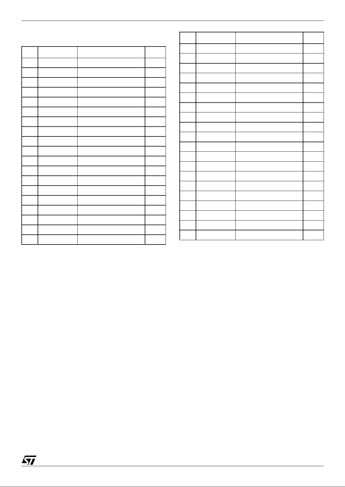
M58BW016BT, M58BW016BB, M58BW016DT, M58BW016DB
Table 2. Top Boot Block Addresses,
M58BW016BT, M58BW016DT
Note: 1. TP = Tuning Protected Block, only available for the
M58BW016B.
# Size (Kbit) Address Range
TP
(1)
38 64 7F800h-7FFFFh yes
37 64 7F000h-7F7FFh yes
36 64 7E800h-7EFFFh no
35 64 7E000h-7E7FFh no
34 64 7D800h-7DFFFh no
33 64 7D000h-7D7FFh no
32 64 7C800h-7CFFFh no
31 64 7C000h-7C7FFh no
30 512 78000h-7BFFFh no
29 512 74000h-77FFFh no
28 512 70000h-73FFFh no
27 512 6C000h-6FFFFh no
26 512 68000h-6BFFFh no
25 512 64000h-67FFFh no
24 512 60000h-63FFFh no
23 512 5C000h-5FFFFh yes
22 512 58000h-5BFFFh yes
21 512 54000h-57FFFh yes
20 512 50000h-53FFFh yes
19 512 4C000h-4FFFFh yes
18 512 48000h-4BFFFh yes
17 512 44000h-47FFFh yes
16 512 40000h-43FFFh yes
15 512 3C000h-3FFFFh yes
14 512 38000h-3BFFFh yes
13 512 34000h-37FFFh yes
12 512 30000h-33FFFh yes
11 512 2C000h-2FFFFh yes
10 512 28000h-2BFFFh yes
9 512 24000h-27FFFh yes
8 512 20000h-23FFFh yes
7 512 1C000h-1FFFFh yes
6 512 18000h-1BFFFh yes
5 512 14000h-17FFFh yes
4 512 10000h-13FFFh yes
3 512 0C000h-0FFFFh yes
2 512 08000h-0BFFFh yes
1 512 04000h-07FFFh yes
0 512 00000h-03FFFh yes
# Size (Kbit) Address Range
TP
(1)
M58BW016BT, M58BW016BB, M58BW016D T, M58BW016DB
12/63
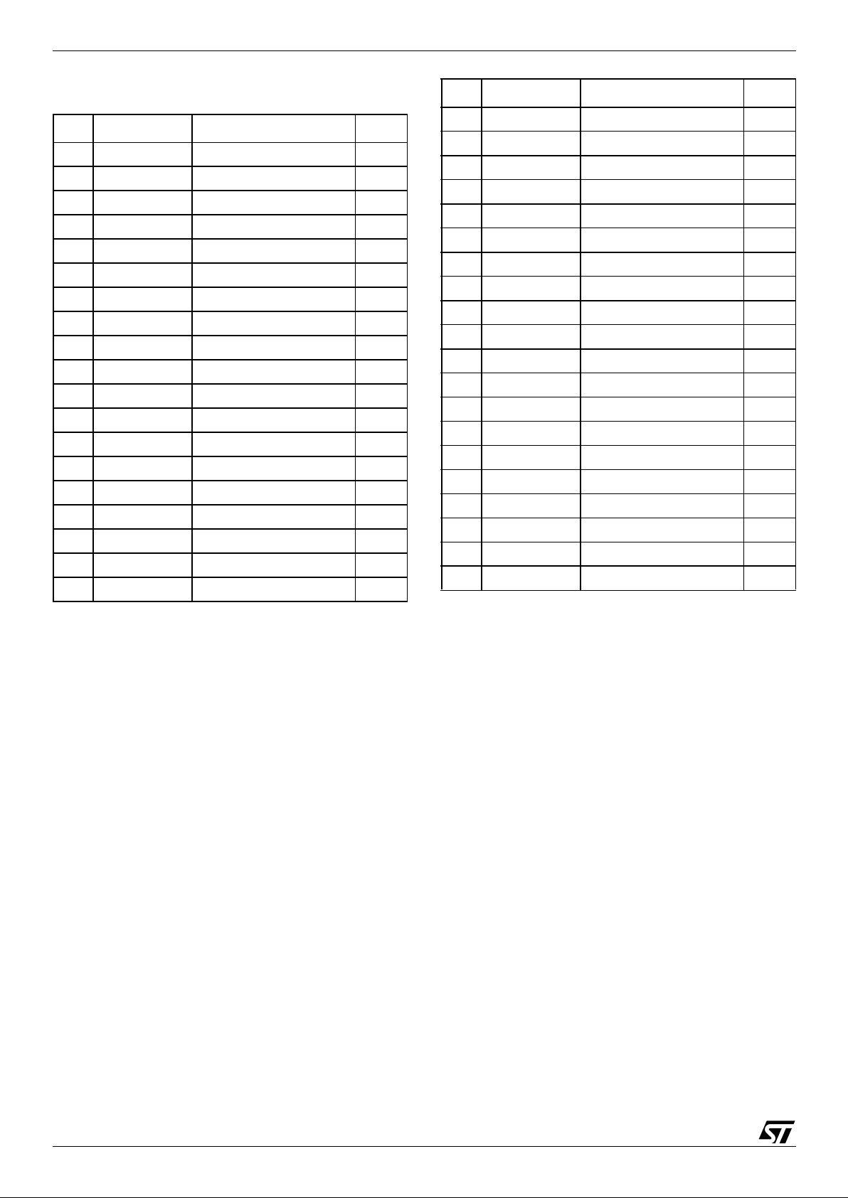
Table 3. Bottom Boot Block Addresses,
M58BW016BB, M58BW016DB
Note: 1. TP = Tuning Protected Block, only available for the
M58BW016B.
# Size (Kbit) Address Range
TP
(1)
38 512 7C000h-7FFFFh yes
37 512 78000h-7BFFFh yes
36 512 74000h-77FFFh yes
35 512 70000h-73FFFh yes
34 512 6C000h-6FFFFh yes
33 512 68000h-6BFFFh yes
32 512 64000h-67FFFh yes
31 512 60000h-63FFFh yes
30 512 5C000h-5FFFFh yes
29 512 58000h-5BFFFh yes
28 512 54000h-57FFFh yes
27 512 50000h-53FFFh yes
26 512 4C000h-4FFFFh yes
25 512 48000h-4BFFFh yes
24 512 44000h-47FFFh yes
23 512 40000h-43FFFh yes
22 512 3C000h-3FFFFh yes
21 512 38000h-3BFFFh yes
20 512 34000h-37FFFh yes
19 512 30000h-33FFFh yes
18 512 2C000h-2FFFFh yes
17 512 28000h-2BFFFh yes
16 512 24000h-27FFFh yes
15 512 20000h-23FFFh yes
14 512 1C000h-1FFFFh no
13 512 18000h-1BFFFh no
12 512 14000h-17FFFh no
11 512 10000h-13FFFh no
10 512 0C000h-0FFFFh no
9 512 08000h-0BFFFh no
8 512 04000h-07FFFh no
7 64 03800h-03FFFh no
6 64 03000h-037FFh no
5 64 02800h-02FFFh no
4 64 02000h-027FFh no
3 64 01800h-01FFFh no
2 64 01000h-017FFh no
1 64 00800h-00FFFh yes
0 64 00000h-007FFh yes
# Size (Kbit) Address Range
TP
(1)

13/63
M58BW016BT, M58BW016BB, M58BW016DT, M58BW016DB
SIGNAL DESCRIPTIONS
See Figure 2, Logic Diagram and Table 1, Signal
Names, for a brief overview of the signals connected to this device.
Address Inputs (A0-A18). The Address Inputs
are used to select the cells to access in the mem ory array during Bus Read operations either to
read or to program data to. During Bus Write operations they control the commands sent to the
Command Interface of the internal state m achine.
Chip Enable must be low when selecting the addresses.
The address inputs are latched on the rising edge
of Latch Enable L
or Burst Clock K, whichever occurs first, in a read operation.The address inputs
are latched on the rising edge of Chip Enable,
Write Enable or Lat ch Enable, whichever o ccurs
first in a Write operation. The address latch is
transparent when Latch Enable is low, V
IL
. The address is internally latched in a n E rase or P rogram
operation.
Data Inputs/Outputs (DQ0-DQ31). The Data Inputs/Outputs output the data stored at the selected
address during a Bus Read operation, or are used
to input the data during a program operation. During Bus Write operations they represent the commands sent to the Command Interface of the
internal state machine. When used to input data or
Write commands they are latched on the rising
edge of Write Enable or Chip Enable, whichever
occurs first.
When Chip Enable and Output Enable are both
low, V
IL
, and Output Disable is at V
IH,
the data bus
outputs data from the memory array, the Electronic Signature, the CFI Information or the contents of
the Status Register. The data bus is high impedance when the device is deselected with Chip Enable at V
IH
, Output E na ble at VIH, Outp u t Di sa b le
at V
IL
or Reset/Power-Down at VIL. The Status
Register content is output on DQ0-DQ7 and DQ8DQ31 are at V
IL
.
Chip Enable (E
). The Chip Enable, E, input acti-
vates the memory control logic, input buffers, decoders and sense amplifiers. Chip Enable, E
, at
V
IH
deselects the memory and reduces the power
consumption to the Standby level.
Output Enable (G
). The Output Enable, G, gates
the outputs through the data output buffers during
a read operation, whe n Output Disable GD
is at
V
IH
. When Output Enable G is at VIH, the outputs
are high impedance in dependentl y of Output Disable.
Output Disable (GD
). The Output Disable, GD,
deactivates the data output buffers. W hen Output
Disable, GD
, is at VIH, the outputs are driven by
the Output Enable. When Output Disable, GD
, is at
V
IL
, the outputs are high impedance independent-
ly of Output Enable. The Output Disable pin must
be connected to an external pull-up resistor as
there is no internal pull-up resistor to drive the pin.
Write Enable (W
). The Write Enable, W, input
controls writing to the Command Interface, Input
Address and Data latches. Both addresses and
data can be latched on the rising edge of Wri te Enable (also see Latch Enable, L
).
Reset/Power-Down (RP
). The Reset/Power-
Down, RP
, is used to apply a hardware reset to the
memory. A hardware reset is achie ved by hold ing
Reset/Power-Down Low, V
IL
, for at least t
PLPH
.
Writing is inhibited to protect data, the Command
Interface and the Program/Erase Controller are reset. The Status Register information is cleared and
power consumption is reduced to deep powerdown level. The device acts as deselected, that is
the data outputs are high impedance.
After Reset/Power-Down goes High, V
IH
, the
memory will be ready for Bus Read operations after a delay of t
PHEL
or Bus Write operat ions after
t
PHWL
.
If Reset/Power-Down goes low, V
IL
, during a Block
Erase, a Program or a Tuning Protection Program
the operation is aborted, in a time of t
PLRH
maxi-
mum, and data is altered and may be corrupted.
During Power-up power should be applied simulta-
neously to V
DD
and V
DDQ(IN)
with RP held at VIL.
When the supplies are stable RP
is taken to VIH.
Output Enable, G
, Chip Enable, E , and Write En-
able, W
, should be held at VIH during power-up.
In an application, it is recommended to associate
Reset/Power-Down pin, RP
, with the reset s ignal
of the microprocessor. Otherwise, if a reset operation occurs while the memory is performing an
erase or program operation, the memory may output the Status Register informa tion instead of being initialized to the default Asynchronous
Random Read.
See Table 21 a nd F igure 18, Reset , Po wer-Down
and Power-up Characteristics, for more details.
Latch Enable (L
). The Bus Interface can be con-
figured to latch the Address Inputs on the rising
edge of Latch Enable, L
, for Asynchronous Latch
Enable Controlled R ead or W rite or Synchronous
Burst Read operations. In Synchronous Burst
Read operations the address is latched on the active edge of the Clock when Latch Ena ble is Low,
V
IL
. Once latched, the addresses may change
without affecting the address used by the memory.
When Latch Enable is Low, V
IL
, the latch is trans-
parent. Latch Enable, L
, can remain at VIL for
Asynchronous Random Read and Write operations.
Burst Clock (K). The Burst Clock, K, is used to
synchronize the memory with the external bus dur-

M58BW016BT, M58BW016BB, M58BW016D T, M58BW016DB
14/63
ing Synchronous Burst Read operations. Bus signals are latched on the active edge of the Clock.
The Clock can be configured to have an active rising or falling edge. In Synchronous Burst Read
mode the address is latched on the first active
clock edge when Latch Enable is low, V
IL
, or on
the rising edge of Latch Enable, whichever occurs
first.
During Asynchronous bus operations the Clock is
not used.
Burst Address Advance (B
). The Burst Address
Advance, B
, controls the advancing of the address
by the internal address counter during Synchronous Burst Read operations.
Burst Address Advance, B
, is only sampled on the
active clock edge of the Clock when the X-latency
time has expired. If Burst Address Advance is
Low, V
IL
, the internal address counter advances. If
Burst Address Advance is High, V
IH
, the internal
address counter does not change ; the same dat a
remains on the Data Inputs/Outputs and Burst Address Advance is not sampl ed until the Y-latency
expires.
The Burst Address Advance, B
, may be tied to VIL.
Valid Data Ready (R). The Valid Data Ready
output, R, is an open drain output that can be
used, during Synchronous Burst Read operations,
to identify if the memory is ready to output data or
not. The Valid Data Ready output can be c onfigured to be active on the clock edge o f the invalid
data read cycle or one cycle before. Valid Data
Ready, at V
IH
, indicate s that new data is or will be
available. When Valid Data Ready is Low, V
IL
, the
previous data outputs remain active.
In all Asynchronous operations, Valid Data Ready
is high-impedance. It may be tied to other components with the same Valid Data Ready signal to
create a unique system Ready signal. The Val id
Data Ready output has an internal pull-up resistor
of around 1 MΩ powered from V
DDQ
, designers
should use an external pull-up resistor of the correct value to meet the external timing requirements for Valid Data Ready going to V
IH
.
Write Protect (WP
). The Write Protect, W P, pro-
vides protection against progra m or erase operations. When Write Protect, WP
, is at VIL the first
two (in the bottom configuration) or last two (in the
top configuration) parameter blocks and all main
blocks are locked. When Write Protect WP
is at
V
IH
all the blocks can be programmed or erased, if
no other protection is used.
Supply Voltage (V
DD
). The Supply Voltage, VDD,
is the core power supp ly. All internal circuits draw
their current from the V
DD
pin, including the Pro-
gram/Erase Controller.
Output Supply Voltage (V
DDQ
). The Output Sup-
ply Voltage, V
DDQ
, is the output buffer power supply
for all operati ons (Read, Pro gram and Era se) used
for DQ0-DQ31 when used as outputs.
Input Supply Voltage (V
DDQIN
). The Input Sup-
ply Voltage, V
DDIN
, is the power supply for all input
signal. Input signals are: K, B
, L, W, GD, G, E, A0-
A18 and D0-D31, when used as inputs.
Program/Erase Supp ly Voltage (V
PP
). The Pro-
gram/Erase Supply V oltage, V
PP
, is used for program and erase operations. The memory normally
executes program and erase operations at V
PP1
voltage levels. In a manufacturing environment,
programming may be speeded up by applying a
higher voltage level, V
PPH
, to the VPP pin.
The voltage level V
PPH
may be applied for a tot al
of 80 hours over a maximum of 1000 cycles.
Stressing the device beyond these limits could
damage the device.
Ground (V
SS
and V
SSQ
). The Ground VSS is the
reference for the internal supply voltage V
DD
. The
Ground V
SSQ
is the reference for the o utput and
input supplies V
DDQ,
and V
DDQIN
. It is essen t ial to
connect V
SS
and V
SSQ
together.
Note: A 0.1µF capacitor should be connected
between the Supply Voltages, V
DD
, V
DDQ
and
V
DDIN
and the Grounds, VSS and V
SSQ
to decouple the current surges from the power supply.
The PCB track widths must be sufficient to carry the currents required during all o perations
of the parts, see Table 15, DC Characteristics,
for maximum current supply requir ements.
Don’t Use (DU). This pin should not be used as it
is internally connected. Its voltage level can be between V
SS
and V
DDQ
or leave it unconnected.
Not Connected (NC). This pin is not physically
connected to the device.

15/63
M58BW016BT, M58BW016BB, M58BW016DT, M58BW016DB
BUS OPERATIONS
Each bus operations that controls the memory is
described in this section, see Tables 4, 5 and 6
Bus Operations, for a summary. The bus operation
is selected through the Burst Configuration Register; the bits in this register are described at the end
of this section.
On Power-up or after a Hardware Reset the memory defaults to Asynchronous Bus Read and Asynchronous Bus W rite, no other b us operation can
be performed until the Burst Control Register has
been configured.
The Electronic Signature, CFI or Status Register
will be r ead in a synchronous mode rega rdless of
the Burst Control Register settings.
Typically glitches of less than 5ns on Chip Enable
or Write Enable are ignored by the memory and do
not affect bus operations.
Asynchronous Bus Operation s
For asynchronous bus operations refer to Table 4
together with the following text.
Asynchronous Bus Read. Asynchronous Bus
Read operations read f rom the memory cells, or
specific registers (Electronic Signature, Status
Register, CFI and Burst Configuration Register) in
the Command Interface. A valid bus ope ration involves setting the desired address on the Address
Inputs, applying a Low signal, V
IL
, to Chip Enable
and Output Enable and keeping Write Enable and
Output Disable High, V
IH
. The Data Inputs/Outputs will output the value, see Figure 9, Asynchronous Bus Read AC Waveforms, and Table 16,
Asynchronous Bus Read AC Characteristics, for
details of when the output becomes valid.
Asynchronous Read is the default read mode
which the device enters on power-up or on return
from Reset/Power-Down.
Asynchronous Latch Controlled Bus Read.
Asynchronous Latch Controlled Bus Read operations read from the memory cells or specific registers in the Command Interface. The address is
latched in the memory before the value i s output
on the data bu s, allowing the address to c hange
during the cycle without affecting the address that
the memory uses.
A valid bus operati on involves s etting the d esired
address on the Address Inputs, setting Chip Enable and Latch Enable Low, V
IL
and keeping Write
Enable High, V
IH
; the address is latched on the rising edge of Latch Enabl e. Once latched, the Address Inputs can change. Set Output Enable Low,
V
IL
, to read the data on the Data Inputs/Outputs;
see Figure 1, Asynchronous Latch Controlled Bus
Read AC Waveforms and Table 17, Asynchronous Latch Controlled Bus Read AC Ch aracteristics for details on when the output becomes valid.
Note that, since the Latch Enable input is transparent when set Low, V
IL
, Asynchronous Bus Read
operations can be performed when the memory is
configured for Asynchronous Latch Enable bus
operations by holding Latch Enable Low, V
IL
throughout the bus operation.
Asynchronous P age R e ad. Asynchronous
Page Read operations are used to read from several addresses within the same memory page.
Each memory page is 4 Double-Words and is addressed by the address inputs A0 and A1.
Data is read internally and stored in the Page Buffer. Valid bus operations are the same as Asynchronous Bus Read operations but with different
timings. The first read operation within the page
has identical timings, subsequent reads within the
same page have much shorter acce ss ti mes. If the
page changes then the normal, longer timings apply again. Page Read does not support Latched
Controlled Read.
See Figure 11, Asynchronous Page Read AC
Waveforms and Table 18, Asynchronous Page
Read AC Characteristics for details on when the
outputs become valid.
Asynchronous Bus Write. Asynchronous Bus
Write operations write to the Command Interface
in order to send commands to the memory or to
latch addresses and input data to program. Bus
Write operations are asynchronous, the clock, K,
is don’t care during Bus Write operations.
A valid Asynchronous Bus W rite operation begins
by setting the desired address on the A ddress Inputs, and setting Chip Enable, Write Enable and
Latch Enable Low, V
IL
, and Output Enable High,
V
IH
, or Output Disable Low, VIL. The Address Inputs are latched by the Command Interface on the
rising edge of Chip Enable or Write Enable, whichever occurs first. Commands and Input Data are
latched on the rising edge of Chip Enable, E
, or
Write Enable, W
, whichever occurs first. Output
Enable must remain High, and Output Disable
Low, during the whole Asynchronous Bus Write
operation.
See Figure 12, Asynchronous Write AC Waveforms, and Table 19, Asynchronous Write and
Latch Controlled Write AC Charact eristics, for details of the timing requirements.
Asynchronous Latch Controlled Bus Write.
Asynchronous Latch Controlled Bus Write operations write to the Command Interface in order to
send commands to the memory or to latch addresses and input data t o program. Bus W rite operations are asynchronous, the c lock, K, is don’t
care during Bus Write operations.
A valid Asynchronous Latch Controlled Bus Write
operation begins by setting the desired address on
M58BW016BT, M58BW016BB, M58BW016D T, M58BW016DB
16/63
the Address Inputs and pulsing Latch Enable Low,
V
IL
. The Address Inputs are latc hed by the Command Interface on the rising edge of Latch Enable,
Write Enable or Chip Enable, whichever occurs
first. Commands and Input Data are latched on the
rising edge of Chip Enable, E
, or Write Enable, W,
whichever occurs first. Output Enable must remain
High, and Output Dis able Low, during the whole
Asynchronous Bus Write operation.
See Figure 13, Asynchronous Latch Controlled
Write AC Waveforms, and Table 19, Asynchronous Write and Latch Controlled Write AC Characteristics, for details of the timing requirements.
Output Disable. The data outputs are high impedance when the Output Enable, G
, is at VIH or
Output Disable, GD
, is at VIL.
Standby. When Chip Enable is High, V
IH
, and the
Program/Erase Controller is id le, the memory enters Standby mode, the power consumption is reduced to the standby level and the Data Inputs/
Outputs pins are placed in the high impedance
state regardless of Output Enable, Write Enable or
Output Disable inputs.
Automatic Low Power. If there is no change in
the state of the bus for a short period of time during
Asynchronous Bus Re ad operations the memory
enters Auto Low Pow er mode where the internal
Supply Current is reduced to the Auto-Standby
Supply Current. The Data Inputs/Outputs will still
output data if a Bus Read operation is in progress.
Automatic Low Power is only available in Asynchronous Read modes.
Power-Down . The memory is in Power-down
when Reset/Power-Down, RP
, is at VIL. The power consumption is reduced to the power-down level and the outputs are high impedance,
independent of the Chip Enable, E
, Output Enable,
G
, Ou t put D i sa b l e, GD , or Wri te Enable, W, inputs.
Electronic Signature. Two codes identifying the
manufacturer and the device can be read from the
memory allowing programming equipment or applications to autom atically mat ch their interface to
the characteristics of the memory. The Electronic
Signature is output by giving the Read Electronic
Signature command. The manufacturer code is
output when all the Address inputs are at V
IL
. The
device code is output when A1 is at V
IH
and all the
other address pins are at V
IL
. See Table 5. Issue
a Read Memory Array command to return to Read
mode.
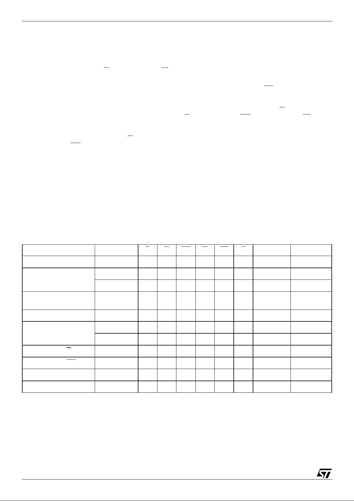
Table 4. Asynchronous Bus Operations
Note: X = Don’ t Ca re
Bus Operation Step E G GD W RP L A0-A18 DQ0-DQ31
Asynchronous Bus Read
V
IL
V
IL
V
IH
V
IH
V
IH
V
IL
Address Data Output
Asynchronous Latch
Controlled Bus Read
Address Latch
V
IL
V
IH
V
IH
V
IL
V
IH
V
IL
Address High Z
Read
V
IL
V
IL
V
IH
V
IH
V
IH
V
IH
X Data Output
Asynchronous Page
Read
V
IL
V
IL
V
IH
V
IH
V
IH
X Address Data Output
Asynchronous Bus Write
V
IL
V
IH
X
V
IL
V
IH
V
IL
Address Data Input
Asynchronous Latch
Controlled Bus Write
Address Latch
V
IL
V
IL
V
IH
V
IH
V
IH
V
IL
Address High Z
Write
V
IL
V
IH
X
V
IL
V
IH
V
IH
X Data Input
Output Disable, G
V
IL
V
IH
V
IH
V
IH
V
IH
X X High Z
Output Disable, GD
V
IL
V
IL
V
IL
V
IH
V
IH
X X High Z
Standby
V
IH
XXX
V
IH
X X High Z
Reset/Power-Down X X X X
V
IL
X X High Z

17/63
M58BW016BT, M58BW016BB, M58BW016DT, M58BW016DB
Table 5. Asynchronous Read Electronic Signature Operation
Note: 1. x= B or D version of the device.
2. BCR= Burst Configuration Register.
Synchronous Bus Operations
For synchronous bus o perations refer to Table 6
together with the following text.
Synchronous Burs t R ea d. Synchronous Burst
Read operations are used to read from the memory at specific times synchronized to an external reference clock. The burst type , length and latency
can be configured. The different configurations for
Synchronous Burst Read operations are described in the Burst Configuration Register section. Refer to Figures 5 and 6 for examples of
synchronous burst operations.
In continuous burst read, one burst read operation
can access the entire memory sequentially by
keeping the Burst Address Advance B
at VIL for
the appropriate number of clock cycles. At the end
of the memory address space t he burst read restarts from the beginning at address 000000h.
A valid Synchronous Burst Read operation begins
when the Burst Clock is active and Chip Enable
and Latch Enable are Low, V
IL
. The burst start address is latched and loaded into the internal B urst
Address Counter on the valid Burst Clock K edge
(rising or falling depending on the value of M6) or
on the rising edge of Latch Ena ble, whichev er occurs first.
After an initial memory latency time, the memory
outputs data each clock cycl e (or two clo ck cycl e s
depending on the value of M9). The Burst Address
Advance B input controls the memory burst output.
The second burst output is on the nex t cloc k valid
edge after the Burst A ddress Advance B
has been
pulled Low.
Valid Data Ready, R, monitors if the memory burst
boundary is exceeded and the Burst Controller of
the microprocessor needs to insert wait states.
When Valid Data Ready is Low on the active clock
edge, no new data is available and the memory
does not increment the internal address counter at
the active clock edge even if Burst Address Advance, B
, is Low.
Valid Data Ready may be configured (by bit M8 of
Burst Configuration Regist er) to be valid imm ediately at the valid clock edge or one data cycle before the valid clock edge.
Synchronous Burst Read will be suspended if
Burst Address Advance, B
, goes High, VIH.
If Output Enable is at V
IL
and Output Disable is at
V
IH
, the last data is still valid.
If Output Enable, G
, is at VIH or Output Disable,
GD
, is at VIL, but the Burst Address Advance, B, is
at V
IL
the internal Burst Addres s Counter is incre-
mented at each Burst Clock K valid edge.
The Synchronous Burst Read timing diagrams
and AC Characteristics are described in the AC
and DC Parameters section. See Figures 14 , 15,
16 and 17, and Table 20.
Synchronous Burst Read Suspend. During a
Synchronous Burst Read operation it is possible to
suspend the operation, freeing the data bus for
other higher priority devices.
A valid Synchronous Burst Read operation is suspended when b oth Output Enable an d Burst Address Advance are H igh, V
IH
. The Burst Address
Advance going High, V
IH
, stops the burst counter
and the Output Enable going High, V
IH
, inhibits th e
data outputs. The Synchronous Burst Read operation can be resumed by setting Output Enable
Low.
Code Device E G GD W A18-A0 DQ31-DQ0
Manufacturer All
V
IL
V
IL
V
IH
V
IH
00000h 00000020h
Device
M58BW016xT
(1)
V
IL
V
IL
V
IH
V
IH
00001h 00008836h
M58BW016xB
(1)
V
IL
V
IL
V
IH
V
IH
00001h 00008835h
Burst Configuration
Register
V
IL
V
IL
V
IH
V
IH
00005h
BCR
(2)

M58BW016BT, M58BW016BB, M58BW016D T, M58BW016DB
18/63
Table 6. Synchronous Burst Read Bus Operations
Note: 1. X = Don't Care, VIL or VIH.
2. M15 = 0, Bit M15 is in the Burst Configuration Register.
3. T = transition, see M6 in the Burst Configurati on Regist er for detail s on the acti ve edge of K.
Bus Operation Step E G GD RP
K
(3)
L B
A0-A18
DQ0-DQ31
Synchronous Burst
Read
Address Latch
V
IL
V
IH
X
V
IH
T
V
IL
X Address Input
Read
V
IL
V
IL
V
IH
V
IH
T
V
IH
V
IL
Data Output
Read Suspend
V
IL
V
IH
X
V
IH
X
V
IH
V
IH
High Z
Read Resume
V
IL
V
IL
V
IH
V
IH
T
V
IH
V
IL
Data Output
Burst Address Advance
V
IL
V
IH
X
V
IH
T
V
IH
V
IL
High Z
Read Abort, E
V
IH
XX
V
IH
X X X High Z
Read Abort, RP
XXX
V
IL
X X X High Z

19/63
M58BW016BT, M58BW016BB, M58BW016DT, M58BW016DB
Burst Configuration Register
The Burst Configuration Register is used to configure the type of bus access that the memory will
perform.
The Burst Configuration Register is set through
the Command Interface and will retain its information until it is re-configured, the device is reset, or
the device goes into Reset/Power-Down mode.
The Burst Configuration Register bits are described in Table 7. They specify the selection of
the burst length, burst type, burst X and Y latencies and the Read operat ion. Refer to Figures 5
and 6 for examples of sync hronous burst configurations.
Read Select Bit (M15). The Read Select bit,
M15, is used to switch between asynchronous and
synchronous Bus Read operations. When the
Read Select bit is set to ’1’, Bus Read operations
are asynchronous; when the Read Select but is
set to ’0’, Bus Read operations are synchronous.
On reset or power-up the Read Select bit is set
to’1’ for asynchronous accesses.
X-Latency Bits (M14-M11). The X-Latency bits
are used during Synchronous Bus Read operations to set the number of clock cycles between
the address being latched and the first data becoming available. For correct operation the X-Latency bits can only assume the values in Table 7,
Burst Configuration Register. The X -Latency bits
should also be selected in conjunction with Table ,
Burst Performance to ensure valid settings.
Y-Latency Bit (M9). The Y-Latency bit is used
during Synchronous Bus Read operations to set
the number of clock cycles between consecutive
reads. The Y-Latency value depends on both the
X-Latency value and the setting in M9.
When the Y-Latency i s 1 the data changes each
clock cycle; when the Y-Latency is 2 the data
changes every se cond clock cycle. See Tab le 7,
Burst Configuration Register and Table , Burst
Performance, for valid combinations of the Y-Latency, the X-Latency and the Clock frequency.
Valid Data Ready Bit (M8). The Valid Data
Ready bit controls the timing of the Valid Data
Ready output pin, R. When the Valid Data Ready
bit is ’0’ the Valid Data Ready output pin is driven
Low for the active clock edge when invalid data is
output on the bus. When the Valid Data Ready bit
is ’1’ the Valid Data Ready output pin is driven Low
one clock cycle prior to invalid data being output
on the bus.
Burst Type B it (M7). The Burst Type bit is used
to configure the sequence of addresses read as
sequential or interleaved. When the Burst Type bit
is ’0’ the memory outputs from interleaved addresses; when the Burst Type bit is ’1’ the memory
outputs from sequential addresses. See Tables 8,
Burst Type Definition, for the sequence of addresses output from a given starting address in
each mode.
Valid Clock Edge Bit (M6). The Valid Clock
Edge bit, M6, is used to configure the active e dge
of the Clock, K, during Synchronous Burst Read
operations. When the Valid Clock Edge bit is ’0’
the falling edge of the Clock is the active edge;
when the Valid Clock Edge bit is ’1’ the rising edge
of the Clock is active.
Wrap Burst Bit (M3). The burst reads can be
confined inside the 4 or 8 Double-Word boundary
(wrap) or overcome the boundary (no wrap). The
Wrap Burst bit is used t o select between wrap and
no wrap. When the Wrap Burst bit is set to ‘0’ the
burst read wraps; when it is set to ‘1’ the burst read
does not wrap.
Burst Length Bit (M2-M0). The Burst Length bits
set the maximum number of Double-Words that
can be output durin g a Synchronous Burst Read
operation before the address wraps. Burst lengths
of 4 or 8 are available for both the Sequential and
Interleaved burst types, and a continuous burst is
available for the Sequential type.
Table 7, Burst Configuration Register gives the
valid combinations of the Burst Length bits that the
memory accepts; Table 8, Burst Ty pe Definition,
gives the sequence of addresses output from a
given starting address for each length.
If either a Continuous or a No Wrap Burs t Read
has been initiated the device will output data synchronously. Depending on the starting address,
the device activates the Valid Dat a Ready output
to indicate that a delay is necessary before the
data is output. If t he s tarting address is align ed t o
an 8 Double Word boundary, the continuous burst
mode will run without activating the Valid Data
Ready output. If the starting address is not aligned
to an 8 Double Word boundary, Valid Data Ready
is activated to indicate that the device needs an internal delay to read the successive words in the array.
M10, M5 and M4 are reserved for future use.

M58BW016BT, M58BW016BB, M58BW016D T, M58BW016DB
20/63
Table 7. Burst Configuration Register
Note: 1. 4 - 2 - 2 - 2 is not allowed.
2. X latenci es can be calculat ed as: (t
AVQV
– t
LLKH
+ t
QVKH
) + t
SYSTEM MARGIN
< (X - 1 ) t
K. (X
is an integer number from 4 to 8 and t
K
is the clock period).
3. Y latencie s c an be calculated as: t
KHQV
+ t
SYSTEM MARGIN
+ t
QVKH
< Y t
K.
4. t
SYSTEM MARGIN
is the time m argin requi red for the c al culation.
Bit Description Value Description
M15 Read Select
0 Synchronous Burst Read
1 Asynchronous Read (Default at power-on)
M14 Reserved
M13-M11
X-Latency
(2)
001 Reserved
010
4, 4-1-1-1
(1)
011 5, 5-1-1-1, 5-2-2-2
100 6, 6-1-1-1, 6-2-2-2
101 7, 7-1-1-1, 7-2-2-2
110 8, 8-1-1-1, 8-2-2-2
M10 Reserved
M9
Y-Latency
(3)
0 One Burst Clock cycle
1 Two Burst Clock cycles
M8 Valid Data Ready
0 R valid Low during valid Burst Clock edge
1 R valid Low one data cycle before valid Burst Clock edge
M7 Burst Type
0 Interleaved
1 Sequential
M6 Valid Clock Edge
0 Falling Burst Clock edge
1 Rising Burst Clock edge
M5-M4 Reserved
M3 Wrapping
0 Wrap
1 No wrap
M2-M0 Burst Length
001 4 Double-Words
010 8 Double-Words
111 Continuous

21/63
M58BW016BT, M58BW016BB, M58BW016DT, M58BW016DB
Table 8. Burst Type Definition
M 3
Starting
Addressx4Sequentialx4Interleaved
x8
Sequential
x8
Interleaved
Continuous
0 0 0-1-2-3 0-1-2-3 0-1-2-3-4-5-6-7 0-1-2-3-4-5-6-7 0-1-2-3-4-5-6-7-8-9-10..
0 1 1-2-3-0 1-0-3-2 1-2-3-4-5-6-7-0 1-0-3-2-5-4-7-6 1-2-3-4-5-6-7-8-9-10-11..
0 2 2-3-0-1 2-3-0-1 2-3-4-5-6-7-0-1 2-3-0-1-6-7-4-5 2-3-4-5-6-7-8-9-10-11-12..
0 3 3-0-1-2 3-2-1-0 3-4-5-6-7-0-1-2 3-2-1-0-7-6-5-4 3-4-5-6-7-8-9-10-11-12-13..
0 4 – – 4-5-6-7-0-1-2-3 4-5-6-7-0-1-2-3 4-5-6-7-8-9-10-11-2-13-14..
0 5 – – 5-6-7-0-1-2-3-4 5-4-7-6-1-0-3-2 5-6-7-8-9-10-11-12-13-14..
0 6 – – 6-7-0-1-2-3-4-5 6-7-4-5-2-3-0-1 6-7-8-9-10-11-12-13-14-15..
0 7 – – 7-0-1-2-3-4-5-6 7-6-5-4-3-2-1-0 7-8-9-10-11-12-13-14-15-16..
0 8 – – – – 8-9-10-11-12-13-14-15-16-17..
1 0 0-1-2-3 – 0-1-2-3-4-5-6-7 – 0-1-2-3-4-5-6-7-8-9-10..
1 1 1-2-3-4 – 1-2-3-4-5-6-7-8 – 1-2-3-4-5-6-7-8-9-10-11..
1 2 2-3-4-5 – 2-3-4-5-6-7-8-9 – 2-3-4-5-6-7-8-9-10-11-12..
1 3 3-4-5-6 – 3-4-5-6-7-8-9-10 – 3-4-5-6-7-8-9-10-11-12-13..
1 4 4-5-6-7 –
4-5-6-7-8-9-10-
11
– 4-5-6-7-8-9-10-11-12-13-14..
1 5 5-6-7-8 –
5-6-7-8-9-10-11-
12
– 5-6-7-8-9-10-11-12-13-14..
1 6 6-7-8-9 –
6-7-8-9-10-11-
12-13
– 6-7-8-9-10-11-12-13-14-15..
1 7 7-8-9-10 –
7-8-9-10-11-12-
13-14
– 7-8-9-10-11-12-13-14-15-16..
1 8 8-9-10-11 –
8-9-10-11-12-13-
14-15
– 8-9-10-11-12-13-14-15-16-17..

M58BW016BT, M58BW016BB, M58BW016D T, M58BW016DB
22/63
Figure 5. Example Burst Configuration X-1-1-1
Figure 6. Example Burst Configuration X-2-2-2
AI03841
K
DQ
L
ADD
VALID
DQ
DQ
DQ
DQ
4-1-1-1
5-1-1-1
6-1-1-1
7-1-1-1
8-1-1-1
0123456789
VALIDVALIDVALIDVALID
VALIDVALIDVALIDVALID
VALID
VALID
VALIDVALIDVALID
VALID
VALID
VALID
VALID
VALIDVALID
VALID
AI04406b
K
L
ADD
DQ
VALID
DQ
DQ
DQ
5-2-2-2
6-2-2-2
7-2-2-2
8-2-2-2
0123456789
VALID
VALID
VALID
VALID
VALID
VALID
VALID
VALID
NV
NV
NV
NV
NV
NV
NV
NV
NVNV
NV=NOT VALID

23/63
M58BW016BT, M58BW016BB, M58BW016DT, M58BW016DB
COMMAND INTERFACE
All Bus Write operations to the memory are in terpreted by the Command Interface. Commands
consist of one or more sequential Bus Write operations. The Commands are summarized in Tab le
9, Commands. Refer to Table 9 in conjunction with
the text descriptions below.
Read Memory Array Command
The Read Memory Array command returns the
memory to Read mode. One Bus Write cycle is required to issue the Read Memory Array command
and return the memory to Read mode. Subsequent read operations will output the addressed
memory array data. Once the command is issued
the memory remains in Read mode u ntil another
command is issued. From Read mode Bus Read
commands will access the memory array.
Read Electronic Signature Command
The Read Electronic Signat ure command is used
to read the Manufacturer Code, the Device Code
or the Burst Configuration Register. One Bus Write
cycle is required to issue the Read Electronic Signature command. Once the command is issued
subsequent Bus R ead operations, depending on
the address specified, read the Manufacturer
Code, the Device Code or the Burst Configuration
Register until another command is issued; see Table 5, Read Electronic Signature.
Read Query Command.
The Read Query Command is used t o read data
from the Common Flash Interface (CFI ) Memory
Area. One Bus Write cycle is required to issue the
Read Query Command. O nce the c om ma nd is issued subsequent Bus Read op erations, depending on the address specified, read from the
Common Flash Interface Memory Area. See Appendix A, Tables 25, 26, 27, 28 and 29 for det ails
on the information contained in the Common Flash
Interface (CFI) memory area.
Read Status Register Command
The Read Status Register command is used to
read the Status Register. One Bus Write cycle is
required to issue the Read Status Register command. Once the command is issued subsequent
Bus Read operations read the Status Register until another command is issued.
The Status Register information is present on t he
output data bus (DQ1-DQ7) when Chip Enable E
and Output Enable G are at VIL and Output Disable is at V
IH
.
An interactive update of the Status Register bits is
possible by toggling Output Enable or Output Disable. It is also possible during a Program or Erase
operation, by disactivating the device with Chip
Enable at V
IH
and then reactivating it with Chip En-
able and Output Enable at V
IL
and Output Disable
at V
IH
.
The content of the Status Register may also be
read at the completion of a Program, Erase or
Suspend operation. During a Block Erase, Program, Tuning Protection Program or Tuning Protection Unlock command, DQ7 indicates the
Program/Erase Controller status. It is valid until
the operation is completed or suspended.
See the sectio n on t he Stat us Register and Ta ble
11 for details on the definitions of the Status Register bits
Clear Status Register Command
The Clear Status Register command can be used
to reset bits 1, 3, 4 and 5 in the Status Register to
‘0’. One Bus Write is required to issue the Clear
Status Register command. On ce the comm and is
issued the memory returns t o its previous mode,
subsequent Bus Read operations conti nue to output the same data.
The bits in the Status Register are s ticky and do
not automatically return to ‘0’ when a new Program, Erase, Block Protect or Block Unprotect
command is issued. If any error occurs then it is
essential to clear any error bits in the Status Register by issuing the Clear Status Register command before attempting a new Program, Erase or
Resume command.
Block Erase Command
The Block Erase c ommand can be used to erase
a block. It sets all of the bits in the block to ‘1’. All
previous data in the block is lost. If the block is protected then the Erase operation will abort, the data
in the block will not be changed and the Status
Register will output the error.
Two Bus Write operations are required to issue the
command; the first write cycle sets up t he Block
Erase command, the second write cycle confirms
the Block erase command a nd latches the block
address in the internal state machine and starts
the Program/Erase Controller. The sequence is
aborted if the Confirm command is not given and
the device will output the Status Register Data with
bits 4 and 5 set to '1'.
Once the command is issued subsequent Bus
Read operations read the Status Register. See the
section on the Status Register for details on the
definitions of the Status Register bits. During the
Erase operation the memory will only accept the
Read Status Register command and the Program/
Erase Suspend command. All other commands
will be igno re d .
The command can be executed using either V
DD
(for a normal erase operation) or VPP (for a fast
erase operation). If V
PP
is in the V
PPH
range when

M58BW016BT, M58BW016BB, M58BW016D T, M58BW016DB
24/63
the command is issued then a fast erase operation
will be exec uted, otherwis e the ope ration wi ll use
V
DD
. If VPP goes below the VPP Lockout Voltage,
V
PPLK
, during a fast erase the operation aborts,
the Status Register V
PP
Status bit is set to ‘1’ and
the command must be re-issued.
Typical Erase times are given in Table 10.
See Appendix B, Figure 23, Block Erase Flowchart
and Pseudo Code, for a suggested flowchart on
using the Block Erase command.
Program Command.
The Program command is used to program the
memory array. Two Bus Write operations are required to issue the command; the first write cycle
sets up the Program com mand, the secon d write
cycle latches the address and data to be programmed in the int ernal state machine a nd starts
the Program/Erase C ontroller. A program operation can be aborted by writing FFFFFFFFh to any
address after the program set-up command has
been given.
Once the command is issued subsequent Bus
Read operations read the Status Register. See the
section on the Status Register for details on the
definitions of the Status Register bits. During the
Program operation the memory will only accept
the Read Status Register com mand and th e Program/Erase Suspend command. All other commands will be ignored.
If Reset/Power-down, RP
, falls to V
IL
during pro-
gramming the operation will be aborted.
The command can be executed using either V
DD
(for a normal program operation) or VPP (for a fast
program operation). If V
PP
is in the V
PPH
range
when the command is issued then a fast program
operation will be executed, otherwise the operation will us e V
DD
. If VPP goes below the VPP Lock-
out Voltage, V
PPLK
, during a fast program the
operation aborts and the Status Register V
PP
Status bit is set to ‘1’. As data integrity cannot be guaranteed when the program operation is aborted, the
memory block must be erased and reprogrammed.
See Appendix B, Figure 21, Program Flowchart
and Pseudo Code, for a suggested flowchart on
using the Program command.
Program/Erase Suspend Command
The Program/Erase Suspend co mm and is u sed to
pause a Program or Erase operation. The command w ill only be accept ed during a Pro gram or
Erase operation. It can be i ssued at any tim e during a program or eras e operation. The c ommand
is ignored if the device is already in suspend
mode.
One Bus Write cycle is required to i ssue the P rogram/Erase Suspend command and pause the
Program/Erase Controller. Once the command is
issued it is necessary to poll the Program/Erase
Controller Status bit (bit 7) to find out when the
Program/Erase Controller has paused; no other
commands will be accepted until the Program/
Erase Controller has paused. After the Program/
Erase Controller has paused, the memory will continue to output the Status Register until another
command is issued.
During the polling period between issuing the Program/Erase Suspend command and the Program/
Erase Controller pausing it is possible for the operation to complete. Once the Program/Erase
Controller Status bit (bit 7) i ndicates that t he Program/Erase Controller is no longer active, the Program Suspend Status bit (bit 2) or the Erase
Suspend Status bit (bit 6) can be used to determine if the operation has completed or is suspended. For timing on the delay between issuing the
Program/Erase Suspend command and the Program/Erase Controller pausing see Table 10.
During Program/Erase Suspend the Read Memory Array, Read Status Register, Read Electronic
Signature, Read Query and Program/Erase Resume commands will be accepted by the Command Interface. Additionally, if the suspended
operation was Erase then the Program and the
Program Suspend com mands will also b e accep ted. When a program operation is completed inside
a Block Erase Suspend the Read Memory Array
command must be issued to reset the device in
Read mode, then the Erase Resume command
can be issued to complete the whole sequence.
Only the blocks not being e rased m ay b e read or
programmed correctly.
See Appendix B, Figure 22, Program Suspend &
Resume Flowchart and Pseudo Code, and Figure
24, Erase Suspend & Resume Flowchart and
Pseudo Code, for suggested flowcharts on using
the Program/Erase Suspend command .
Program/Er ase Resu me Command
The Program/Erase Resume command can be
used to restart the Program/Erase Controller after
a Program/Erase Suspend operation has paused
it. One Bus Write cycle is required to issue the Program/Erase Resume command.
See Appendix B, Figure 22, Program Suspend &
Resume Flowchart and Pseudo Code, and Figure
24, Erase Suspend & Resume Flowchart and
Pseudo Code, for suggested flowcharts on using
the Program/Erase Resume command.
Set Burst Configuration Register Command.
The Set Burst Configuration Register command is
used to write a new val ue to the Burst Configuration Control Register which defines the burst
length, type, X and Y latencies, Synchronous/

25/63
M58BW016BT, M58BW016BB, M58BW016DT, M58BW016DB
Asynchronous Read mode and the valid Clock
edge configuration.
Two Bus Writ e cycl es are require d to issue th e Se t
Burst Configuration Register command. The first
cycle writes the setup command and the address
corresponding to the Set Burst Configuration Register content. The second cycle writes the Burst
Configuration Register data and the confirm command. Once the command is issued the memory
returns to Read mode as if a Rea d M emo ry Array
command had been issued.
The value for the Burst Configuration Register is
always presented on A0-A15. M0 is on A0, M1 on
A1, etc.; the other address bits are ignored.
Tuning Prot ection U nl ock Command
The Tuning Protection Unlock command unlocks
the tuning protected blocks by writing the 64bit
Tuning Protection Code (M58BW016B only). After
a reset or power-up the blo cks are locked a nd so
a Tuning Protection Unlock comm and must be issued to allow program or erase operations on tuning protected block or to program a new Tuning
Protection Code. Read ope rations output the Status Register content after the unlock operation has
started.
The Tuning Protection Code is composed of 64
bits, but the data bus is 32 bits wide so f our (2 x 2)
write cycles are required to unlock the device.
■ The first write cycle issues the Tuning
Protection Unlock Setup command (0x78).
■ The second write cycle inputs the first 32 bits of
the tuning protection code on the data bus, at
address 0x00000.
Bit 7 of the Status Register should now be
checked to verify that t he de vice has successfully
stored the first part of the code in the internal register. If b7 = ‘1’, the device is ready to accept the
second part of the code. This does not mean that
the first 32 bits match the tuning protection code,
simply that it was c orrect ly st ored for the com paring. If b7 = ‘0’, the user must wait for this bit setting
(refer to write cycle AC timings).
■ The third write cycle re-issues the Tuning
Protection Unlock Setup command (0x78).
■ The fourth write cycle inputs the second 32 bits
of the code at address 0x00001.
Bit 7 of the Status Register should again be
checked to verify that t he de vice has successfully
stored the second part of the code. When the device is ready (b7 = ‘1’), the tuning protection status
can be monitored on Status Register bit0. If b0 =
‘0’ the device is locked; b0 = ‘1’ the device is unlocked. If the device is still locked a Read Memory
Array command must be issued before re-issuing
the Tuning Protection Unlock command.
Device locked means that the 64 bit password is
wrong. If the unlock operation is attempted using a
wrong code on an already unlocked device, the
device becomes locked. Status register bit 4 is set
to '1' if there has been a verify failure.
Unlocking aborts if V
PP
drops out of the allowed
range or RP
goes to VIL.
Once the device is successfully unlocked, a Read
Memory Array command must be issued to return
the memory to read mode before issuing any other
commands. The user can then program or erase
all blocks, depending on WP
status and VPP level.
At this point, it is a lso possible to configure a new
protection code. To write a new protection code
into the device tuning register, the user must perform the Tuning Protection Program sequence.
The device can be re-locked with a reset or powerdown.
See Appendix B, Figure 25, 26 and 27 for suggested flowcharts for using t he Tuning P rotection Unlock command.
Tuning Prot ection Pr ogram Com m and.
The Tuning Protection Program command is used
to program a new Tuning Protection Code which
can be configured by the designer of the application (M58BW016B only). The device should be unlocked by the Tuning Protection Unlock command
before issuing the Tuning Protection Program
command.
Read operations output the Status Register content after the program operation has started.
The Tuning Protection Code is composed of 64
bits, but the data bus is 32 bits wide so f our (2 x 2)
write cycles are required to program the code.
■ The first write cycle issues the Tuning
Protection Program Setup command (0x48).
■ The second write cycle inputs the first 32 bits of
the new tuning protection code on the data bus,
at address 0x00000.
Bit 7 of the Status Register should now be
checked to verify that t he de vic e has successfully
stored the first part of the code in the internal register. If b7 = ‘ 1’, the device is ready to ac cept the
second part of the code. If b7 = ‘0’, the user must
wait for this bit setting (refer to write cycle AC timings).
■ The third write cycle re-issues the Tuning
Protection Program Setup command (0x48).
■ The fourth write cycle inputs the second 32 bits
of the new code at address 0x00001.
Bit 7 of the Status Register should again be
checked to verify that t he de vic e has successfully
stored the second part of the code. When the device is ready (b7 = ‘1’). After completion Status

M58BW016BT, M58BW016BB, M58BW016D T, M58BW016DB
26/63
Register bit 4 is set to '1' if there has b een a program failure.
Programming aborts if V
PP
drops out of the al-
lowed range or RP
goes to VIL.
A Read Memory Array com mand must be issued
to return the memory to read mode before issuing
any other commands. Once the code has been
changed a device reset or power-down will make
the protection active with the new code.
See Appendix B, Figure 25, 26 and 27 for suggested flowcharts for using the Tuning Protection Program command.
Table 9. Commands
Note: 1. X Don’t Care; RA Read Address, RD R ead Data, I D Device Code, SRD St atus Regi ster Dat a, PA Program Addr ess; PD Pr ogram
Data, QA Que ry Addr es s, QD Qu ery D ata, BA A ny addr ess in the Block, B CR Burst Config ur ation R egis ter v alue , TPA = Tuni ng
Protection Addres s, T P C = T uning Pro tection Code.
2. Cycles 1 an d 2 i nput the firs t 32 bits of the code, cyc l es 3 and 4 the sec ond 32 bits of t he code.
Command
Cycles
Bus Operations
1st Cycle 2nd Cycle 3rd Cycle 4th Cycle
Op. Addr. Data Op. Addr. Data Op. Addr. Data Op. Addr. Data
Read Memor y Array ≥ 2 Write X FFh Read RA RD
Read Electronic Signa ture
(Manufacturer Code)
≥ 2 Write X 90h Read 00000h 20h
Read Electronic Signa ture
(Device Code)
≥ 2 Write X 90h Read 00001h IDh
Read Electronic Signa ture
(Burst Configuration
Register)
≥ 2 Write X 90h Read 00005h BCRh
Read Status Register 2 Writ e X 70h Read X SRDh
Read Quer y ≥ 2 Writ e X 98h Re ad QAh QDh
Clear Status Register 1 Writ e X 50h
Block Erase 2 Write X 20h Write BAh D0h
Program 2 Write X
40h
10h
Write PA PD
Program/Erase Suspend 1 Write X B0h
Program/Erase Resume 1 Write X D0h
Set Burst Configuration
Register
2 Write X 60h Write BCRh 03h
Tuning Protection
(2)
Program
4 Write X 48h Write TPAh TPCh Write X 48h Write TPAh TPCh
T uning Protection Unlock
(2)
4 Write X 78h Write TPAh TPCh Write X 78h Write TP Ah TPCh

27/63
M58BW016BT, M58BW016BB, M58BW016DT, M58BW016DB
Table 10. Program, Erase Times and Program Erase Endurance Cycles
Note: TA = –40 to 125° C, VDD = 2.7V to 3.6V , V
DDQ
= 2.4V to V
DD
Parameters
M58BW016B/D
Unit
Min T yp Max
V
PP
= V
DD
VPP = 12V VPP = V
DD
VPP = 12V
Parameter Block (64Kb) Program 0.030 0.016 0.060 0.032 s
Main Block (512Kb) Program 0.23 0.13 0.46 0.26 s
Parameter Block Erase 0.8 0.64 1.8 1.5 s
Main Block Erase 1.5 0.9 3 1.8 s
Program Suspend Latency Time 3 10 µs
Erase Suspend Latency Time 10 30 µs
Program/Erase Cycles (per Block) 100,000 cycles

M58BW016BT, M58BW016BB, M58BW016D T, M58BW016DB
28/63
STATUS REGISTER
The Status Register provides information on the
current or previous Program, Erase, Block Protect
or Tuning Protection operation. The various bits in
the Status Register convey information and errors
on the operation. They are output on DQ7-DQ0.
To read the Status Register the Read Status Register command can be issued. The Status Register
is automatically read after Program, Erase, Block
Protect, Program/Erase Resume commands . The
Status Register can be read from any address.
The contents of the Status Register can be updated during an erase or program operation by toggling the Output Enable or Output Disable pins or
by dis-activating (Chip Enable, V
IH
) and then reac-
tivating (Chip Enable and Output Enable, V
IL
, and
Output Disable, V
IH
.) the device.
The Status Register bits are summarized in Table
11, Status Register Bits. Refer to Table 11 in conjunction with the following text descriptions.
Program/Erase Contr oller Status (Bit 7)
The Program/Erase Controller Status bit indicates
whether the Program/Erase Con troller is active or
inactive. When the Program/Erase Controller Status bit is set to ‘0’, the Program/Erase Controller is
active; when bit7 is set to ‘1’, the Program/Erase
Controller is inactive.
The Program/Erase Controller Status is set to ‘0’
immediately after a Program/Erase Suspend command is issued until the Program/Erase Controller
pauses. After the Program/Erase Controller pauses the bit is set to ‘1’.
During Program and Erase operations the Program/Erase Controller Status bit ca n be polled to
find the end of the operation. The oth er bits in t he
Status Register should not be tested until the Program/Erase Controller completes the operation
and the bit is set to ‘1’.
After the Program/Erase Controller completes its
operation the Erase Statu s (bit5 ), Program S tatus
and Tuning Protection Unlock status (bit4) bits
should be tested for errors.
Erase Suspend Status (Bit 6)
The Erase Suspend Status bit indicates that an
Erase operation has been suspended and is waiting to be resumed. The Erase Suspend Status
should only be considered valid when the Program/Erase Controller Status bit is set to ‘1’ (Program/Erase Controller inactive); after a Program/
Erase Suspend command is issued the memory
may still complete the operation rather than entering the Suspend mode.
When the Erase Suspend Status bit is set to ‘0’,
the Program/Erase Controller is active or has completed its operation; when the bit is set to ‘1’, a Program/Erase Suspe nd command has been iss ued
and the memory is waiting for a Program/Erase
Resume command.
When a Program/Erase Re sume command is issued the Erase Suspend Status bit returns to ‘0’.
Erase Status (Bit 5)
The Erase Status bit can be used to identify if the
memory has failed to verify that the block has
erased correctly. The Erase Status bit should be
read once the Program/Erase Controller Status bit
is High (Program/Erase Controller inactive).
When the Erase Status bit is set to ‘0’, the memory
has successfully verified that the block has erased
correctly. When the Erase St atus bit is set to ‘1’,
the Program/Erase Controller has applied the
maximum number of pulses t o the block and still
failed to verify that the block has erased correctly.
Once set to ‘1’, the Erase Status bit can only be reset to ‘0’ by a Clear Status Register command or a
hardware reset. If set to ‘1’ it should be reset before a new Program or Erase command is issued,
otherwise the new command will appear to fail.
Program Status, Tuning Protection Unlock
Status (Bit 4)
The Program Status and Tuning Protection Unlock
Status bit is used to identify a Program failure or a
Tuning Protection Code verify failure. Bit4 should
be read once the Program/Erase Controller Status
bit is High (Program/Erase Controller inactive).
When bit4 is set to ‘0’ the memory has successfully verified that the device has programmed correctly or that the correct Tuning Protection Code
has been written. When bit4 is set to ‘1’ the device
has failed to verify that the data has been programmed correctly or that the corre ct Tu ning Protection code has been written.
Once set to 1’, the Program Status bit can only be
reset to ‘0’ by a Clear Status Register command or
a hardware reset. If set to ‘1’ it should be reset before a new Program or Erase command is issued,
otherwise the new command will appear to fail.
V
PP
Status (Bit 3)
The V
PP
Status bit can be used to identify an in-
valid voltage on the V
PP
pin during fast program
and erase operations. The V
PP
pin is only sampled
at the beginning of a program or erase operation.
Indeterminate resul ts can occur i f V
PP
becomes in-
valid during a fast Program or Erase operation.
When the V
PP
Status bit is set to ‘0’, the voltage on
the V
PP
pin was sampled at a valid voltage; when
the V
PP
Status bit is set to ‘1’, t he VPP pin has a
voltage that is below the V
PP
Lockout Voltage, V
P-
PLK
.
Once set to ‘1’, the V
PP
Status bit can only be reset
to ‘0’ by a Clear Status Register command or a
hardware reset. If set to ‘1’ it should be reset be-

29/63
M58BW016BT, M58BW016BB, M58BW016DT, M58BW016DB
fore a new Program or Erase command is issued,
otherwise the new command will appear to fail.
Program Suspend Status (Bit 2)
The Program S uspend Status bit i ndicates that a
Program operation has been suspended and is
waiting to be resumed. The Program Suspend
Status should only be consid ered valid when the
Program/Erase Controller Status bit is set to ‘1’
(Program/Erase Controller inactive); after a Program/Erase Suspend command is issued the
memory may still complete the operation rather
than entering the Suspend mode.
When the Program Suspend Status bit is set to ‘0’,
the Program/Erase Controller is active or has completed its operation; when the bit is set to ‘1’, a Program/Erase Suspe nd command has been iss ued
and the memory is waiting for a Program/Erase
Resume command.
When a Program/Erase Re sume command is issued the Program Suspend Status bit returns to
‘0’.
Block Protection Status (Bit 1)
The Block Protection Status bit can be used to
identify if a Program or Erase op eration has tried
to modify the contents of a protected block.
When the Block Protection Status bit is set to ‘0’,
no Program or Erase operations have been attempted to protected blocks since the last Clear
Status Register command or hardware reset;
when the Block Protection Status bit is set to ‘1’, a
Program or Erase operat ion has been attempted
on a protected block.
Once set to ‘1’, the Block Protection Status bit can
only be reset Low by a Clear Status Register command or a hardware reset. If set to ‘1’ it should be
reset before a new Program or Erase command is
issued, otherwise the new command will appear to
fail.
Tuning Prot ection Stat us (Bit 0)
The Tuning Protection Status bit indicates if the
device is locked (Tuning P rot ectio n is enable d) or
unlocked (Tuning Protection is disabled).
When the Tuning Prot ec tion Status bi t is s et to ‘ 0’
the device is locked, when it is set to ‘1’ the device
is unlocked. After a reset or power-up the device is
locked and so bit0 is set to ‘0’.
The Tuning Protection Status bit is set to ‘1’ for the
M58BW016D version.
Table 11. Status Register Bits
Note: 1. F or the M58B W016D version the Tuning Pro tection St atus bit is al ways set t o ‘ 1’ .
Bit Name Logic Level Definition
7
Program/Erase Controller Status
’1’ Ready
’0’ Busy
6
Erase Suspend Status
’1’ Suspended
’0’ In Progress or Completed
5
Erase Status
’1’ Erase Error
’0’ Erase Success
4
Program Status,
Tuning Protection Unlock Status
’1’ Program Error
’0’ Program Success
3
V
PP
Status
’1’
V
PP
Invalid, Abort
’0’
V
PP
OK
2
Program Suspend Status
’1’ Suspended
’0’ In Progress or Completed
1
Erase/Program in a Protected
Block
’1’
Program/Erase on Protected Block,
Abort
’0’ No Operations to Protected Sectors
0
Tuning Protection Status
’1’
Tuning Protection Disabled
(1)
’0’ Tuning Protection Enabled

M58BW016BT, M58BW016BB, M58BW016D T, M58BW016DB
30/63
MAXIMUM RATING
Stressing the device above the ratings listed in Table 12, Absolute Maximum Ratings, may cause
permanent damage to the device. These are
stress ratings only and operation of t he device at
these or any other conditions above those indicated in the Operating sections of this specification is
not implied. Exposure to Abs olute M aximum Ra ting conditions for extended periods may affect device reliability. Refer also to the
STMicroelectronics SURE Program and other relevant quality documents.
Table 12. Absolute Maximum Ratings
Note: Cumulative time at a hi gh voltage l evel of 13.5V should not exc eed 80 hours on VPP pin.
Symbol Parameter
Value
Unit
Min Max
T
BIAS
Temperature Under Bias –40 125 °C
T
STG
Storage Temperature –55 155 °C
V
IO
Input or Output Voltage –0.6
V
DDQ
+0.6
V
DDQIN
+0.6
V
V
DD
, V
DDQ, VDDQIN
Supply Voltage –0.6 4.2 V
V
PP
Program Voltage –0.6
13.5
(1)
V

31/63
M58BW016BT, M58BW016BB, M58BW016DT, M58BW016DB
DC AND AC PARAMETERS
This section summarizes t he operating and measurement conditions, and the DC and AC characteristics of the device. The parameters i n the DC
and AC characteristics Tables that follow, are derived from tests performed under the Measure-
ment Conditions summarized in Table 13,
Operating and AC Meas urement Conditions. Designers should check that the operating conditions
in their circuit match the measurement conditions
when relying on the quoted parameters.
Table 13. Operating and AC Measurement Conditions
Figure 7. AC Measurement Input Ou t put
Waveform
Note: VDD = V
DDQ
.
Figure 8. AC Measurem e nt Load Circui t
Table 14. Device Capacitance
Note: 1. TA = 25°C, f = 1 MHz
2. Sampled only, not 100% tested.
Parameter
Value
Units
Min Max
Supply Voltage (V
DD
)
2.7 3.6 V
Input/Output Supply Voltage (V
DDQ
)
2.4
V
DD
V
Ambient Temperature (T
A
)
Grade 6 –40 90 °C
Grade 3 –40 125 °C
Load Capacitance (C
L
)
60 pF
Clock Rise and Fall Times 4 ns
Input Rise and Fall Times 4 ns
Input Pulses Voltages
0 to V
DDQ
V
Input and Output Timing Ref. Voltages
V
DDQ
/2
V
AI04153
V
DDQ
V
DDQIN
0V
V
DDQ
/2
V
DDQIN
/2
AI04154
1.3V
OUT
CL
CL includes JIG capacitance
3.3kΩ
1N914
DEVICE
UNDER
TEST
Symbol Parameter Test Condition Typ Max Unit
C
IN
Input Capacitance
V
IN
= 0V
68pF
C
OUT
Output Capacitance
V
OUT
= 0V
812pF

M58BW016BT, M58BW016BB, M58BW016D T, M58BW016DB
32/63
Table 15. DC Characteristics
Symbol Parameter Test Condition Min Max Unit
I
LI
Input Leakage Curren t
0V≤ V
IN
≤ V
DDQ
±1 µA
I
LO
Output Leakage Current
0V
≤ V
OUT
≤V
DDQ
±5 µA
I
DD
Supply Current (Random Read)
E
= VIL, G = VIH, f
add
= 6MHz
20 mA
I
DDB
Supply Current (Burst Read)
E
= VIL, G = VIH, f
clock
=
56MHz
30 mA
I
DD1
Supply Current (Standby)
E
= RP = VDD ± 0.2V
60 µA
Supply Current (Auto Low-Power)
E
= VSS ± 0.2V,
RP = VDD ± 0.2V
60 µA
I
DD2
Supply Current (Reset/Power-down)
RP
= VSS ± 0.2V
60 µA
I
DD3
Supply Current (Program or Erase,
Set Lock Bit, Erase Lock Bit)
Program, Block Erase in
progress
30 mA
I
DD4
Supply Current
(Erase/Program Suspend)
E
= V
IH
40 µA
I
PP
Program Current (Read or Standby)
V
PP
≥ V
PP1
± 30 µA
I
PP1
Program Current (Read or Standby)
V
PP
≤ V
PP1
± 30 µA
I
PP2
Program Current (Power-down)
RP
= V
IL
± 5 µA
I
PP3
Program Current (Program)
Program in Progress
VPP = V
PP1
200 µA
V
PP
= V
PPH
20 mA
I
PP4
Program Current (Erase)
Erase in Progress
VPP = V
PP1
200 µA
VPP = V
PPH
20 mA
V
IL
Input Low Voltage –0.5
0.2V
DDQIN
V
V
IH
Input High Voltage (for DQ lines)
0.8V
DDQIN
V
DDQ
+0.3
V
V
IH
Input High Voltage (for Input only
lines)
0.8V
DDQIN
3.6 V
V
OL
Output Low Voltage
I
OL
= 100µA
0.1 V
V
OH
Output High Voltage CMOS
I
OH
= –100µA V
DDQ
–0.1
V
V
PP1
Program Voltage
(Program or Erase operations)
2.7 3.6 V
V
PPH
Program Voltage
(Program or Erase operations)
11.4 12.6 V
V
LKO
VDD Supply Voltage (Erase and
Program lockout)
2.2 V
V
PPLK
VPP Supply Voltage (Erase and
Program lockout)
11.4 V

33/63
M58BW016BT, M58BW016BB, M58BW016DT, M58BW016DB
Figure 9. Asynchronous Bus Read AC Waveforms
Table 16. Asynchronous Bus Read AC Characteristics.
Note: 1. O utput Ena bl e G m ay be delay ed up to t
ELQV
- t
GLQV
after the falling edge of Chip Enable E without increasing t
ELQV
.
Symbol Parameter Test Condition
M58BW016
Unit
80 90 100
t
AVAV
Address Valid to Address Valid
E
= VIL, G = V
IL
Min 80 90 100 ns
t
AVQV
Address Valid to Output Valid
E
= VIL, G = V
IL
Max 80 90 100 ns
t
AXQX
Address Transition to Output Transition
E
= VIL, G = V
IL
Min 0 0 0 ns
t
EHLX
Chip Enable High to Latch Enable Transition Min 0 0 0 ns
t
EHQX
Chip Enable High to Output Transition
G
= V
IL
Min 0 0 0 ns
t
EHQZ
Chip Enable High to Output Hi-Z
G
= V
IL
Max 20 20 20 ns
t
ELQV
(1)
Chip Enable Low to Output Valid
G
= V
IL
Max 80 90 100 ns
t
ELQX
Chip Enable Low to Output Transition
G
= V
IL
Min 0 0 0 ns
t
GHQX
Output Enable High to Output Transition
E
= V
IL
Min 0 0 0 ns
t
GHQZ
Output Enable High to Output Hi-Z
E
= V
IL
Max 15 15 15 ns
t
GLQV
Output Enable Low to Output Valid
E
= V
IL
Max 25 25 25 ns
t
GLQX
Output Enable to Output Transition
E
= V
IL
Min 0 0 0 ns
t
LLEL
Latch Enable Low to Chip Enable Low Min 0 0 0 ns
E
G
L
A0-A18
DQ0-DQ31
VALID
tLLEL
tAXQX
tELQX
tELQV
tAVQV
tGLQX
tGLQV
tEHQX
tEHQZ
tGHQX
tGHQZ
See also Page Read
OUTPUT
tEHLX
tAVAV
GD
AI04407C
E
G
L
A0-A18
DQ0-DQ31
VALID
tLLEL
tAXQX
tELQX
tELQV
tAVQV
tGLQX
tGLQV
tEHQX
tEHQZ
tGHQX
tGHQZ
See also Page Read
OUTPUT
tEHLX
tAVAV
GD

M58BW016BT, M58BW016BB, M58BW016D T, M58BW016DB
34/63
Figure 10. Asynchronous Latch Controlled Bus Read AC Waveforms
Table 17. Asynchronou s Latch Controlled Bu s Read AC Characteris tics
Symbol Parame ter Test Condition
M58BW016
Unit
80 90 100
t
AVLL
Address Valid to Latch Enable Low
E
= V
IL
Min 0 0 0 ns
t
EHLX
Chip Enable High to Latch Enable Transition Min 0 0 0 ns
t
EHQX
Chip Enable High to Output Transition
G
= V
IL
Min 0 0 0 ns
t
EHQZ
Chip Enable High to Output Hi-Z
G
= V
IL
Max 20 20 20 ns
t
ELLL
Chip Enable Low to Latch Enable Low Min 0 0 0 ns
t
GHQX
Output Enable High to Output Transition
E
= V
IL
Min 0 0 0 ns
t
GHQZ
Output Enable High to Output Hi-Z
E
= V
IL
Max 15 15 15 ns
t
GLQV
Output Enable Low to Output Valid
E
= V
IL
Max 25 25 25 ns
t
GLQX
Output Enable Low to Output Transition
E
= V
IL
Min 0 0 0 ns
t
LHAX
Latch Enable High to Address Transition
E
= V
IL
Min 5 5 5 ns
t
LHLL
Latch Enable High to Latch Enable Low Min 10 10 10 ns
t
LLLH
Latch Enable Low to Latch Enable High
E
= V
IL
Min 10 10 10 ns
t
LLQV
Latch Enable Low to Output Valid
E
= VIL, G = V
IL
Max 80 90 100 ns
t
LLQX
Latch Enable Low to Output Transition
E
= VIL, G = V
IL
Min 0 0 0 ns
AI03645
L
E
G
A0-A18
DQ0-DQ31
VALID
tEHLXtLHLL
tLHAXtAVLL
tELLL
tLLLH
tEHQX
tEHQZ
tGHQX
GHQZ
tLLQX
tLLQV
tGLQX
tGLQV
See also Page Read
OUTPUT

35/63
M58BW016BT, M58BW016BB, M58BW016DT, M58BW016DB
Figure 11. Asynchronous Page Read AC Waveforms
Table 18. Asynchronous Page Read AC Characteristics
Note: For othe r ti m i ngs see Ta ble 16, Asynchron ous Bus Rea d Characteristic s.
Symbol Parameter Test Condition
M58BW016
Unit
80 90 100
t
AVQV1
Address Valid to Output Valid
E
= VIL, G = V
IL
Max 25 25 25 ns
t
AXQX
Address Transition to Output Transition
E
= VIL, G = V
IL
Min666ns
AI03646
A0-A1
DQ0-DQ31
A0 and/or A1
tAVQV1
OUTPUT
tAXQX
OUTPUT + 1

M58BW016BT, M58BW016BB, M58BW016D T, M58BW016DB
36/63
Figure 12. Asynchronous Write AC Waveform
AI03651
DQ0-DQ31
W
RP
A0-A18
E = L
G
INPUT
VALID VALID
tWHEH
VALID
tAVWH
tWLWH
tELWL
INPUT VALID SR
V
PP
tWHAX
tWHWL
tWHDX
tDVWH
tWHGL
tWHQV
tVPHWH
tQVVPL
tQVPL
tPHWH
RP = V
DD
RP = V
HH
Read Status RegisterWrite CycleWrite Cycle
tAVLL

37/63
M58BW016BT, M58BW016BB, M58BW016DT, M58BW016DB
Figure 13. Asy n c hr onous Latc h Controlled W ri te AC Waveform
AI03652
DQ0-DQ31
W
RP
A0-A18
L
G
INPUT
VALID VALID VALID
tAVLH
INPUT
VALID SR
V
PP
tLHAX
Read Status RegisterWrite CycleWrite Cycle
E
tLLLH
tLLWH
tWHAX
tELWL
tWLWH
tWHEH
tWHWL tWHGL
tWHQV
tDVWH
tWHDX
tVPHWH tQVVPL
tQVPL
RP = V
HH
RP = V
DD
tAVWH
tELLL
tAVLL

M58BW016BT, M58BW016BB, M58BW016D T, M58BW016DB
38/63
Table 19. Asynchronous Write and Latch Controlled Write AC Characteristic s
Symbol Parameter Test Condition
M58BW016
Unit
80 90 100
t
AVLL
Address Valid to Latch Enable Low Min 0 0 0 ns
t
AVWH
Address Valid to Write Enable High
E
= V
IL
Min 50 50 50 ns
t
DVWH
Data Input Valid to Write Enable High
E
= V
IL
Min 50 50 50 ns
t
ELLL
Chip Enable Low to Latch Enable Low Min 0 0 0 ns
t
ELWL
Chip Enable Low to Write Enable Low Min 0 0 0 ns
t
LHAX
Latch Enable High to Address Transition Min 5 5 5 ns
t
LLLH
Latch Enable Low to Latch Enable High Min 10 10 10 ns
t
LLWH
latch Enable Low to Write Enable High
E
= V
IL
Min 50 50 50 ns
t
QVVPL
Output Valid to VPP Low
Min 0 0 0 ns
t
VPHWH
VPP High to Write Enable High
Min 0 0 0 ns
t
WHAX
Write Enable High to Address Transition
E
= V
IL
Min 0 0 0 ns
t
WHDX
Write Enable High to Input Transition
E
= V
IL
Min 0 0 0 ns
t
WHEH
Write Enable High to Chip Enable High Min 0 0 0 ns
t
WHGL
Write Enable High to Output Enable Low Min 150 150 150 ns
t
WHQV
Write Enable High to Output Valid Min 175 175 175 ns
t
WHWL
Write Enable High to Write Enable Low Min 20 20 20 ns
t
WLWH
Write Enable Low to Write Enable High
E
= V
IL
Min 60 60 60 ns
t
QVPL
Output Valid to Reset/Power-down Low Min 0 0 0 ns

39/63
M58BW016BT, M58BW016BB, M58BW016DT, M58BW016DB
Figure 14. Synchronous Burst Read (Data Valid from ’n’ Clock Rising Edge)
AI04409
DQ0-DQ31
A0-A18
L
E
G
K
VALID
tKHAX
n+2n+1n
1
0
tKHLL
tLLKH
tELLL
tAVLL
tKHLX
tEHQX
tEHQZ
tGHQX
tGHQZ
tGLQV
Setup
OUTPUT
tKHQV tQVKH
tAVQV
Note: n depends on Burst X-Latency.

M58BW016BT, M58BW016BB, M58BW016D T, M58BW016DB
40/63
Table 20. Synchronous Burst Read AC Characteristics
Note: 1. Data output should be read on the vali d clock edge.
2. For other t i m ings see Tabl e 16, Asy nchronou s B us Read Ch aracteri stics.
Figure 15. Synchronous Burst Read (Data Valid from ’n’ Clock Rising Edge)
Note: For set up si gnals and timings see Synch ronous Burst Read.
Symbol Parameter Test Condition
M58BW016
Unit
80 90 100
t
AVLL
Address Valid to Latch Enable Low
E
= V
IL
Min 0 0 0 ns
t
BHKH
Burst Address Advance High to Valid Clock
Edge
E
= VIL, G = VIL,
L = V
IH
Min 8 8 8 ns
t
BLKH
Burst Address Advance Low to Valid Clock
Edge
E
= VIL, G = VIL,
L
= V
IH
Min 8 8 8 ns
t
ELLL
Chip Enable Low to Latch Enable low Min 0 0 0 ns
t
GLQV
Output Enable Low to Output Valid
E
= VIL, L = V
IH
Min 25 25 25 ns
t
KHAX
Valid Clock Edge to Address Transition
E
= V
IL
Min 5 5 5 ns
t
KHLL
Valid Clock Edge to Latch Enable Low
E
= V
IL
Min 0 0 0 ns
t
KHLX
Valid Clock Edge to Latch Enable Transition
E
= V
IL
Min 0 0 0 ns
t
KHQX
Valid Clock Edge to Output Transition
E
= VIL, G = VIL,
L = V
IH
Min 3 3 3 ns
t
LLKH
Latch Enable Low to Valid Clock Edge
E
= V
IL
Min 6 6 6 ns
t
QVKH
(1)
Output Valid to Valid Clock Edge
E
= VIL, G = VIL,
L
= V
IH
Min 6 6 6 ns
t
RLKH
Valid Data Ready Low to Valid Clock Edge
E
= VIL, G = VIL,
L = V
IH
Min 6 6 6 ns
t
KHQV
Valid Clock Edge to Output Valid
E
= VIL, G = VIL,
L = V
IH
Max 11 11 11 ns
AI04408b
K
n+5
n+4
n+3
n+2
n+1
n
DQ0-DQ31
tQVKH
tKHQX
Q0 Q1 Q2 Q3 Q4 Q5
SETUP
Burst Read
Q0 to Q3
tKHQV
Note: n depends on Burst X-Latency

41/63
M58BW016BT, M58BW016BB, M58BW016DT, M58BW016DB
Figure 16. Synchronous Burst Read - Continuous - Valid Data Ready Output
Note: Valid Data Ready = Vali d Low during valid clock edge
1. V= Val i d output.
2. R is an open drain output with an internal pull up resistor of 1MΩ. The internal timing of R follows DQ. An external resistor, typically
300kΩ. for a singl e memory on the R bus, shou l d be used to give th e data valid se t up time required to recognize that val i d data is
available on the next valid clock edge.
Figure 17. Synchronous Burst Read - Burst Address Advance
AI03649
K
Output
(1)
VVVV
tRLKH
R
V
(2)
AI03650
K
ADD
Q0 Q1
L
Q2
ADD
VALID
G
tGLQV
tBLKH tBHKH
B

M58BW016BT, M58BW016BB, M58BW016D T, M58BW016DB
42/63
Figure 18. Reset, Power-Down and Power-up AC Waveform
Table 21. Reset, Power-Down and Power-u p AC Charac teris tics
Note: 1. This time is t
PHEL
+ t
AVQV
or t
PHEL
+ t
ELQV
.
Symbol Parameter Min Max Unit
t
PHEL
Reset/Power-down High to Chip Enable Low 50 ns
t
PHQV
(1)
Reset/Power-down High to Output Valid
130
ns
t
PHWL
Reset/Power-down High to Write Enable Low 50 ns
t
PHGL
Reset/Power-down High to Output Enable Low 50 ns
t
PLPH
Reset/Power-down Low to Reset/Power-down High 100 ns
t
PLRH
Reset/Power-down Low to Valid Data Ready High 2 30 µs
t
VDHPH
Supply Voltages High to Reset/Power-down High 10 µs
AI03849b
W,
RP
tPHWL
tPHEL
tPHGL
E, G
VDD, VDDQ
tVDHPH
tPHWL
tPHEL
tPHGL
tPLPH
tPLRH
Power-Up Reset
R

43/63
M58BW016BT, M58BW016BB, M58BW016DT, M58BW016DB
PACKAGE MECHANICAL
Figure 19. LBGA80 10x12mm - 8x10 ball array, 1mm pitch, Bottom View Pac kage Ou tline
Note: Drawing is not to scale.
Table 22. LBGA80 10x12mm - 8x10 ball array, 1mm pi tch, Packa ge Mechan ic al Data
Symbol
millimeters inches
Typ Min Max Typ Min Max
A 1.700 0.0669
A1 0.400 0.350 0.450 0.0157 0.0138 0 .0177
A2 1.100 0.0433
b 0.500 – – 0.0197 – –
D 10.000 – – 0.3937 – –
D1 7.000 – – 0.2756 – –
ddd 0.150 0.0059
E 12.000 – – 0.4724 – –
E1 9.000 – – 0.3543 – –
e 1.000 – – 0.0394 – –
FD 1.500 – – 0.0591 – –
FE 1.500 – – 0.0591 – –
SD 0.500 – – 0.0197 – –
SE 0.500 – – 0.0197 – –
E1E
D1
D
eb
A2
A1
A
BGA-Z05
ddd
FD
FE
SD
SE
e
BALL "A1"

M58BW016BT, M58BW016BB, M58BW016D T, M58BW016DB
44/63
Figure 20. PQFP80 - 80 lead Plastic Quad Flat Pack, Package Outline
Note: Drawing is not to scale.
Table 23. PQFP80 - 80 lead Plastic Quad Flat Pack, Package Mechan ical Data
Symbol
millimeters inches
Typ Min Max Typ Min Max
A 3.400 0.1339
A1 0.250 0.0098
A2 2.800 2.550 3.050 0.1102 0.1004 0 .1201
b 0.300 0.450 0.0118 0.0177
c 0.130 0.23 0 0.0051 0.0091
D 23.200 22.950 23.4 50 0.9134 0.9035 0 .9232
D1 20.000 19.900 20.100 0.7874 0.7835 0.7913
D2 18.400 – – 0.7244 – –
e 0.800 – – 0.0315 – –
E 17.200 16.950 17.450 0.6772 0.6 673 0.6870
E1 14.000 13.900 14.100 0.5512 0.5 472 0.5551
E2 12.000 – – 0.4724 – –
L 0.800 0.650 0.950 0.0315 0.0 256 0.0374
L1 1.600 – – 0.0630 – –
α 0° 7° 0° 7°
N80 80
Nd 24 24
Ne 16 16
QFP-B
D1
CP
b
e
A2
A
N
LA1 α
E1
E2
1
D
c
E
D2
L1
Nd
Ne

45/63
M58BW016BT, M58BW016BB, M58BW016DT, M58BW016DB
PART NUMBERING
Table 24. Ordering Information Scheme
Note: Devices are shipped from the factory with the memory content bits erased to ’1’.
For a list of available options (Speed, P ackage, et c...) or for further information on any as pe ct of t his de-
vice, please contact the ST Sales Office nearest to you.
Example: M58BW016B T 80 T 3 T
Device Type
M58
Architecture
B = Burst Mode
Operating Voltage
W = V
DD
= 2.7V to 3.6V; V
DDQ
= V
DDQIN
=2.4 to V
DD
Device Function
016B = 16 Mbit (x32), Boot Block, Burst Tuning Protection
016D = 16 Mbit (x32), Boot Block, Burst no Tuning Protection
Array Matrix
T = Top Boot
B = Bottom Boot
Speed
80 = 80ns
90 = 90ns
100 = 100ns
Package
T = PQFP80
ZA = LBGA80: 1.0mm pitch
Temperature Range
3 = –40 to 125 °C
6 = –40 to 85 °C
Option
T = Tape & Reel Packing

M58BW016BT, M58BW016BB, M58BW016D T, M58BW016DB
46/63
APPENDIX A. COMMON FLASH INTERFACE - CFI
The Common Flash Interface is a JEDEC approved, standardized data structure that can be
read from the Flash memory device. It allows a
system software to query the de vic e to determine
various electrical and timing parameters, density
information and function s supported by t he memory. The system can interface easily with the de-
vice, enabling the software to upgrade itself when
necessary.
When the CFI Query Command (RCFI) is issued
the device enters CFI Que ry mode and the data
structure is read from the memory. Tables 25 , 26,
27, 28 and 29 show the addresses used to retrieve
the data.
Table 25. Query Structure Overview
Note: 1. Offset 15h defines P which points to the Primary Algori thm Extend ed Query Address Tabl e.
2. Offset 19h defines A which points to the Alternate Algorithm Extended Query Address Tabl e.
Table 26. CFI - Query Address and Data Output
Note: 1. The x8 or Byte Address and the x16 or Word Address mode are not available.
2. Query Data are alway s presented on DQ7-DQ0. DQ31-DQ8 are set to ' 0' .
Offset Sub-section Name Description
00h Manufacturer Code
01h Device Code
10h CFI Query Identification String Command set ID and algorithm data offset
1Bh System Interface Information Device timing and voltage information
27h Device Geometry Definition Flash memory layout
P(h)
(1)
Primary Algorithm-specific Extended Query Table
Additional information specific to the Primary
Algorithm (optional)
A(h)
(2)
Alternate Algorithm-specific Extended Query Table
Additional information specific to the Alternate
Algorithm (optional)
Address
A0-A18
Data Instruction
10h 51h "Q"
51h; "Q"
Query ASCII String 52h; "R"
59h; "Y"
11h 52h "R"
12h 59h "Y"
13h 03h
Primary Vendor:
Command Set and Control Interface ID Code
14h 00h
15h 35h
Primary algorithm extended Query Address Table: P(h)
16h 00h
17h 00h
Alternate Vendor:
Command Set and Control Interface ID Code
18h 00h
19h 00h
Alternate Algorithm Extended Query address Table
1Ah
00h

47/63
M58BW016BT, M58BW016BB, M58BW016DT, M58BW016DB
Table 27. CFI - Device Voltage and Timing Specification
Note: 1. Bit s are coded i n Binary Code Decimal , bi t7 to bit4 are s caled in Volts and bit3 t o bi t0 in mV.
2. Bit7 to bit4 are coded in Hexadeci m al and scaled in Volt s while bi t3 to bit0 are in B i nary Code Decimal an d sc al ed in 100m V.
3. Not supp ort ed.
Table 28. Device Geometry Definition
Address A0-A18
Data Description
1Bh
27h
(1)
VDD min, 2.7V
1Ch
36h
(1)
VDD max, 3.6V
1Dh
B4h
(2)
VPP min
1Eh
C6h
(2)
VPP max
1Fh
00h
(3)
2n ms typical time-out for Word, DWord prog – Not Available
20h
00h
(3)
2n ms, typical time-out for max buffer write – Not Available
21h 0Ah
2
n
ms, typical time-out for Erase Block
22h
00h
(3)
2n ms, typical time-out for chip erase – Not Available
23h
00h
(3)
2n x typical for Word Dword time-out max – Not Available
24h 00h
2
n
x typical for buffer write time-out max – Not Available
25h 04h
2
n
x typical for individual block erase time-out maximum
26h
00h
(3)
2n x typical for chip erase max time-out – Not Available
Address
A0-A18
Data Description
27h 15h
2
n
number of bytes memory size
28h 03h Device Interface Sync./Async.
29h 00h Organization Sync./Async.
2Ah 00h
Page size in bytes, 2
n
2Bh 00h
2Ch 02h Bit7-0 = number of Erase Block Regions in device
2Dh 1Eh
Number (n-1) of blocks of identical size; n=31
2Eh 00h
2Fh 00h
Erase Block region information x 256 bytes per
Erase Block (64Kbytes)
30h 01h
31h 07h
Number (n-1) of blocks of identical size; n=8
32h 00h
33h 20h
Erase Block region information x 256 bytes per
Erase Block (8Kbytes)
34h 00h

M58BW016BT, M58BW016BB, M58BW016D T, M58BW016DB
48/63
Table 29. Extended Query information
Note: 1. Not supported.
Address
offset
Address
A18-A0
Data (Hex) Description
(P)h 35h 50h "P"
Query ASCII string - Extended Table(P+1)h 36h 52h "R"
(P+2)h 37h 49h "Y"
(P+3)h 38h 31h Major version number
(P+4)h 39h 31h Minor version number
(P+5)h 3Ah 86h
Optional Feature: (1=yes, 0=no)
bit0, Chip Erase Supported (0=no)
bit1, Suspend Erase Supported (1=yes)
bit2, Suspend Program Supported (1=yes)
bit3, Lock/Unlock Supported (1=yes)
bit4, Queue Erase Supported (0=no)
Bit 31-5 reserved for future use
(P+6)h 3Bh 01h
Optional Features: Synchronous Read supported(P+7)h 3Ch 00h
(P+8)h 3Dh 00h
(P+9)h 3Eh 01h
Function allowed after Suspend:
Program allowed after Erase Suspend (1=yes)
Bit 7-1 reserved for future use
(P+A)h 3Fh
00h
(1)
Block Status Register Mask – Not Available

49/63
M58BW016BT, M58BW016BB, M58BW016DT, M58BW016DB
APPENDIX B. FLOW CHARTS
Figure 21. P rogram Flowchart an d Pseudo Code
Note: 1. If an error is f ound, the Status Regi ster mus t be cl eared before further P/E op erations .
Write 40h
AI03850
Start
Write Address
& Data
Read Status
Register
YES
NO
b7 = 1
YES
NO
b3 = 0
NO
b4 = 0
VPP Invalid
Error (1)
Program
Error (1)
Program Command:
– write 40h
– write Address & Data
(memory enters read status
state after the Program command)
do:
– read status register
(E or G must be toggled)
while b7 = 1
If b3 = 1, VPP invalid error:
– error handler
If b4 = 1, Program error:
– error handler
YES
End
NO
b1 = 0
Program to Protect
Block Error
If b1 = 1, Program to Protected Block Error:
– error handler
YES

M58BW016BT, M58BW016BB, M58BW016D T, M58BW016DB
50/63
Figure 22. Program Suspend & Resume Flowchart and Pseudo Code
Write 70h
AI00612
Read Status
Register
YES
NO
b7 = 1
YES
NO
b2 = 1
Program Continues
Write FFh
Program/Erase Suspend Command:
– write B0h
– write 70h
do:
– read status register
while b7 = 1
If b4 = 0, Program completed
Read Memory Array Command:
– write FFh
– one or more data reads
from other blocks
Write D0h
Program Erase Resume Command:
– write D0h
to resume erasure
– if the program operation completed
then this is not necessary. The device
returns to Read Array as normal
(as if the Program/Erase Suspend
command was not issued).
Read data from
another block
Start
Write B0h
Program Complete
Write FFh
Read Data

51/63
M58BW016BT, M58BW016BB, M58BW016DT, M58BW016DB
Figure 23. Block Erase Flowchart and Pseudo Code
Note: 1. If an error is f ound, the Status Regi ster mus t be cl eared before further P/E op erations .
Write 20h
AI03851
Start
Write Block Address
& D0h
Read Status
Register
YES
NO
b7 = 1
YES
NO
b3 = 0
YES
b4 and b5
= 1
VPP Invalid
Error (1)
Command
Sequence Error
Erase Command:
– write 20h
– write Block Address
(A11-A18) & D0h
(memory enters read status
state after the Erase command)
do:
– read status register
(E or G must be toggled)
if Erase command given execute
suspend erase loop
while b7 = 1
If b3 = 1, VPP invalid error:
– error handler
If b4, b5 = 1, Command Sequence error:
– error handler
NO
NO
b5 = 0
Erase
Error (1)
YES
NO
Suspend
Suspend
Loop
If b5 = 1, Erase error:
– error handler
YES
End
YES
NO
b1 = 0
Erase to Protected
Block Error
If b1 = 1, Erase to Protected Block Error:
– error handler

M58BW016BT, M58BW016BB, M58BW016D T, M58BW016DB
52/63
Figure 24. Erase Suspend & Resume Flowchart and Pseud o Code
Write 70h
AI00615
Read Status
Register
YES
NO
b7 = 1
YES
NO
b6 = 1
Erase Continues
Write FFh
Program/Erase Suspend Command:
– write B0h
– write 70h
do:
– read status register
while b7 = 1
If b6 = 0, Erase completed
Read Memory Array command:
– write FFh
– one or more data reads
from other blocks
Write D0h
Read data from
another block
or Program
Start
Write B0h
Erase Complete
Write FFh
Read Data
Program/Erase Resume command:
– write D0h to resume the Erase
operation
– if the Program operation completed
then this is not necessary. The device
returns to Read mode as normal
(as if the Program/Erase suspend
was not issued).

53/63
M58BW016BT, M58BW016BB, M58BW016DT, M58BW016DB
Figure 25. Unlock Device and Change Tuning Protection Code Flowchart
AI04501
Reset
Device locked
by tuning code
1st: Write Cycle
2nd: Write Cycle
(old code,
factory setup = 0xFFFFh)
YES
3rd: Write Cycle
4th: Write Cycle
(old code,
factory setup = 0xFFFFh)
YES
YES
NO
DEVICE LOCKED
Add: don't care
Data: 0x48h
6th: Write Cycle
Add: 0x00000h
Data: First 32 bit
7th: Write Cycle
(new code)
YES
b7 = 1
Add: don't care
Data: 0x48h
8th: Write Cycle
Add: 0x00001h
Data: Second 32 bit
9th: Write Cycle
(new code)
YES
b7 = 1
DEVICE UNLOCKED
Reset
Device locked
by new code
TUNING PROTECTION
UNLOCK SEQUENCE
Add: don't care
Data: 0xFFh
5th: Write Cycle
Issue Read command
Issue
Read
command
Add: don't care
Data: 0x78h
Add: 0x00000h
Data: First 32 bit
b7 = 1
Add: don't care
Data: 0x78h
Add: 0x00001h
Data: Second 32 bit
b7 = 1
Read Status
Register
b0 = 1
Add: don't care
Data: 0xFFh

M58BW016BT, M58BW016BB, M58BW016D T, M58BW016DB
54/63
Figure 26. Unlock Device and Program a Tuning Protected Block Flowchart
AI04502
Reset
Device locked
by tuning code
Add: don't care
Data: 0x78h
1st: Write Cycle
Add: 0x00000h
Data: First 32 bit
2nd: Write Cycle
(First part
of the tuning code)
YES
b7 = 1
Add: don't care
Data: 0x78h
3rd: Write Cycle
Add: 0x00001h
Data: Second 32 bit
4th: Write Cycle
(Second part
of the tuning code)
YES
b7 = 1
YES
NO
b0 = 1
DEVICE LOCKED
Add: don't care
Data: 0x40h
6th: Write Cycle
Add: location to prog.
Data: data to prog.
7th: Write Cycle
YES
b7 = 1
DEVICE UNLOCKED
Status Register
check
Location
programmed
TUNING PROTECTION
UNLOCK SEQUENCE
Add: don't care
Data: 0xFFh
Issue Read command
5th: Write Cycle
Add: don't care
Data: 0xFFh
Issue
Read
command
Read Status
Register

55/63
M58BW016BT, M58BW016BB, M58BW016DT, M58BW016DB
Figure 27. Unlock Device and Erase a Tuning Protected Block Flowchart
AI04502
Reset
Device locked
by tuning code
Add: don't care
Data: 0x78h
1st: Write Cycle
Add: 0x00000h
Data: First 32 bit
2nd: Write Cycle
(First part
of the tuning code)
YES
b7 = 1
Add: don't care
Data: 0x78h
3rd: Write Cycle
Add: 0x00001h
Data: Second 32 bit
4th: Write Cycle
(Second part
of the tuning code)
YES
b7 = 1
YES
NO
b0 = 1
DEVICE LOCKED
Add: don't care
Data: 0x20h
6th: Write Cycle
Add: block to erase
Data: 0xD0h
7th: Write Cycle
YES
b7 = 1
DEVICE UNLOCKED
Status Register
check
Block
Erased
TUNING PROTECTION
UNLOCK SEQUENCE
Add: don't care
Data: 0xFFh
Issue Read command
5th: Write Cycle
Add: don't care
Data: 0xFFh
Issue
Read
command
Read Status
Register

M58BW016BT, M58BW016BB, M58BW016D T, M58BW016DB
56/63
Figure 28. Power-up Sequence to Burst the Flash
AI03834
Power-up
or Reset
Asynchronous Read
Write 60h command
Write 03h with A15-A0
BCR inputs
Synchronous Read
BCR bit 15 = '1'
Set Burst Configuration Register Command:
– write 60h
– write 03h
and BCR on A15-A0
BCR bit 15 = '0'
BCR bit 14-bit 0 = '1'

57/63
M58BW016BT, M58BW016BB, M58BW016DT, M58BW016DB
Figure 29. Command Interface and Program E rase Control ler Flowch art (a)
AI03835
READ ELEC.
SIGNATURE
YES
NO
90h
READ
STATUS
YES
70h
NO
ERASE
SET-UP
YES
20h
NO
PROGRAM
SET-UP
YES
40h
NO
CLEAR
STATUS
YES
50h
NO
WAIT FOR
COMMAND
WRITE
READ
STATUS
READ
ARRAY
YES
D
B
C
READ CFI
YES
98h
NO
NO
D0h
A
ERASE
COMMAND
ERROR
E
D

M58BW016BT, M58BW016BB, M58BW016D T, M58BW016DB
58/63
Figure 30. Command Interface and Program E rase Control ler Flowch art (b)
AI03836
TP
PROGRAM
SET_UP
YES
NO
48h
SET BCR
SET_UP
YES
60h
NO
D
TP
UNLOCK
SET_UP
YES
78h
NO
FFh
03h
NO
YES
NO
E
F
G
YES

59/63
M58BW016BT, M58BW016BB, M58BW016DT, M58BW016DB
Figure 31. Command Interface and Program E rase Control ler Flowch art (c)
READ
STATUS
70h
B
ERASE
READY
NO
A
B0h
NO
READ
STATUS
YES
READY
NO
ERASE
SUSPEND
YES
READ
ARRAY
YES
ERASE
SUSPENDED
READ
STATUS
YES
NO
40h
NO
D0h
NO
PROGRAM
SET_UP
AI03837
YES
YES
NO YES
READ
STATUS
C

M58BW016BT, M58BW016BB, M58BW016D T, M58BW016DB
60/63
Figure 32. Command Interface and Program E rase Control ler Flowch art (d)
READ
STATUS
70h
B
PROGRAM
READY
NO
C
B0h
NO
READ
STATUS
YES
READY
NO
PROGRAM
SUSPEND
READ
ARRAY
YES
PROGRAM
SUSPENDED
READ
STATUS
YES
NO
NO
D0h
AI03838
YES
NO YES
READ
STATUS
YES

61/63
M58BW016BT, M58BW016BB, M58BW016DT, M58BW016DB
Figure 33. Command Interface and Program E rase Control ler Flowch art (e)
B
TP
PROGRAM
READY
F
NO
READ
STATUS
AI03839
YES
B
TP
UNLOCK
READY
G
NO
READ
STATUS
YES

M58BW016BT, M58BW016BB, M58BW016D T, M58BW016DB
62/63
REVISION HISTORY
Table 30. Document Revision History
Date Version Revision Details
January-2001 -01 First Issue.
05-Jun-2001 -02 Major rewrite and restructure.
15-Jun-2001 -03 Nd and Ne values changed in PQFP80 Package Mechanical Table
17-Jul-2001 -04 PQFP80 Package Outline Drawing and Mechanical Data Table updated
17-Dec-2001 -05
tLEAD removed from Absolute Maximum Ratings (Table 12)
80, 90 and 100ns Speed classes defined (Tables 16, 17, 18, 19 and 20 clarified
accordingly)
Figures 14, 15, 16 and 17 clarified
Temperature range 3 and 6 added
Tables 13, 14, 15, 21 and CFI Tables 26, 27, 28, 29 clarified
Document status changed from Product Preview to Preliminary Data
17-Jan-2002 -06
DC Characteristics I
PP
, I
PP1
and I
DD1
clarified
AC Bus Read Characteristics timing t
GHQZ
clarified
30-Aug-2002 6.1
Revision numbering modified: a minor revision will be indicated by incrementing the
tenths digit, and a major revision, by incrementing the units digit of the previous
version (e.g. revision version 06 becomes 6.0).
References of V
PP
pin used for block protection purposes removed. Figure 9
modified.
4-Sep-2002 7.0
Datasheet status changed from Preliminary Data to full Datasheet.
t
WLWH
parameter modified in Table 19, Asynchronous Write and Latch Controlled
Write AC Characteristics.
13-May-2003 7.1
Revision History moved to end of document. V
PP
clarified in Program and Block
Erase commands and Status Register, VPP Status bit. V
PPLK
added to DC
Characteristics Table. Timing T
KHQV
modified.

63/63
M58BW016BT, M58BW016BB, M58BW016DT, M58BW016DB
Informa tion furnis hed is believed to be accurate and reliab l e. However, STMicroel ectronics assumes no responsibility for t he co nsequen ces
of use of such information nor for any infringement of patents or other rights of third parties which may result from its use. No license is granted
by implication or otherwise unde r any patent or pat ent rights of STM i croelec tr onics. Specificat i ons ment i oned in th i s publicat i on are subject
to change without notice. This publication supersedes and replaces all information previously supplied. STMicroelectronics products are not
authoriz ed for use as c ri tical components in l i fe support devices or systems wit hout express writt en approval of STMicro el ectronics.
The ST logo is regis tered trademark of STM i croelec tronics
All other names are the prope rt y of their respective owners
2003 STMicroelectronics - All Rights Reserved
STMicroelectron ics GROUP OF COMPANIES
Australia - Brazil - Canada - Chi na - Finland - Franc e - Germany - Hong Kong - I ndia - Isra el - It al y - Japan - M al aysia - Mal ta -
Morocco - Singa pore - Spain - Sw eden - Swit zerland - United Kingdom - Uni ted States
www.st.com
 Loading...