

Datasheet LM334Z, LM334D, LM334, LM234Z, LM234 Datasheet (SGS Thomson Microelectronics)
...
THREETERMINAL ADJUSTABLECURRENT SOURCES
.OPERATESfrom1V to 40V
.0.02%V CURRENT REGULATION
.PROGRAMMABLEfrom1µAto10mA
.±3% INITIALACCURACY
DESC RIP TI ON
The LM134/LM234/LM334 are 3-terminal adjustable currentsourcescharacterizedby :
-an operatingcurrent rangeof 10000 : 1
-an excellentcurrentregulation
-a widedynamicvoltage range of 1V to 40V
The current is determined by an external resistor
withoutrequiringother externalcomponents.
Reversevoltagesof up to 20V will only draw a current of several microamperes. This enables the
circuittooperateasa rectifierandasasourceofcurrentin a.c. applications.
For the LM134/LM234/LM334,the voltage on the
controlpin is 64mV at+25
tionaltotheabsolutetemperature(
external resistor connection generates a current
with ≈ 0.33%/
o
C temperature dependence. Zero
driftcanbeobtainedbyaddinganadditionalresistor
and a diode to theexternalcircuit.
o
C and is directlypropor-
o
K).Thesimplest
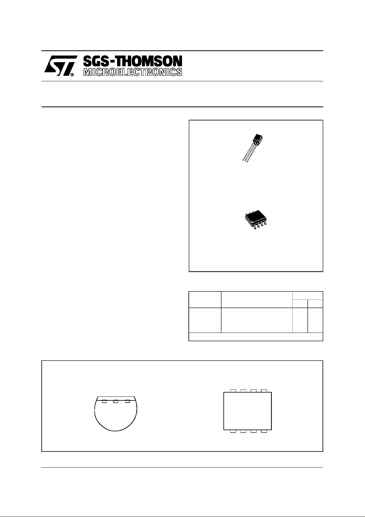
LM134-LM234
(Plastic Package)
(PlasticMicropackage)
ORDER CODES
Part Num-
ber
LM134 –55
LM234 –25
LM334 0
Example : LM134Z
LM334
Z
TO92
D
SO8
Temperature
Range
o
C, +125oC ••
o
C, +100oC ••
o
C, +70oC ••
Package
ZD
PIN CONNECTIO N S
TO92
(Bottomview)
ADJ
-
V
3
+
V
21
October1997 1/10
SO8
(Topview)
NC NC
8765
1234
ADJ NC NC
-
V NC
+
V
LM134-LM234-LM334
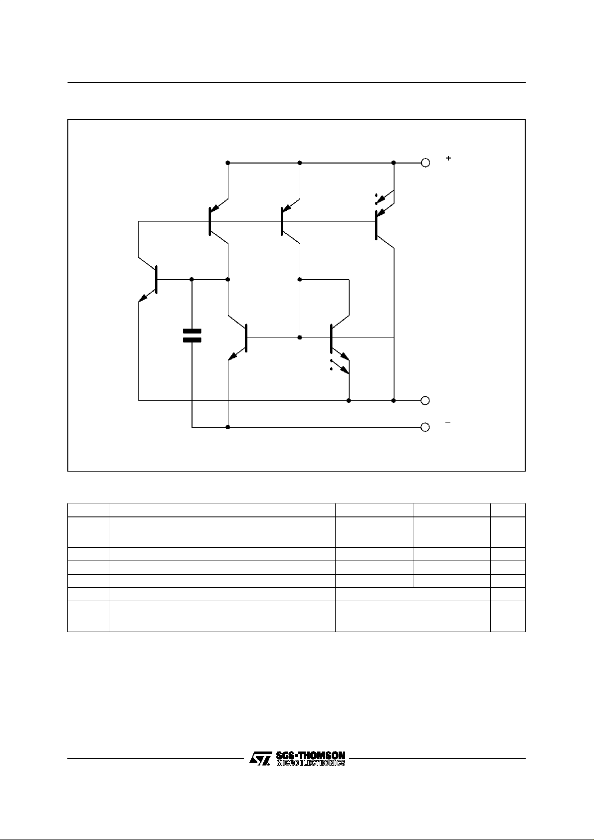
SCHEMA TIC DIAG RAM
Q3
V
Q4 Q5 Q6
C1
Q1
Q2
50pF
ADJ
V
ABSOLUTE MAXIMUM RATING
Symbol Parameter LM134 - LM234 LM334 Unit
Voltage V
-
V
ADJ
I
SET
P
T
T
ADJ Pin to V–Voltage 5 5 V
Set Current 10 10 mA
Power Dissipation 400 400 mW
tot
Storage Temperature Range –65 to +150
stg
Operating Free-air Temperature Range LM134
oper
Forward
Reverse
+
to V
–
LM234
LM334
40
20
–55 to +125
–25 to +100
0 to +70
30
20
V
o
C
o
C
2/10
LM134-LM234-LM334
ELECTRICAL CHARACTERISTICS
= +25oC with pulsetesting so that junction temperature does not change during testing
T
j
(unless otherwise specified)
Parameter
+
Set Current Error (V
10µA ≤ I
1mA ≤ I
2µA ≤ I
SET
SET
SET
Ratio of Set Current to V
10µA ≤ I
1mA ≤ I
2µA ≤ I
SET
SET
SET
= +2.5V) - (note 1)
≤ 1mA
≤ 5mA
≤ 10µA
≤ 1mA
≤ 5mA
≤ 10µA
–
Current
Minimum Operating Voltage
SET
SET
SET
≤ 100µA
≤ 1mA
≤ 5mA
2µA ≤ I
100µA ≤ I
1mA ≤ I
Average change in set current with input voltage
2µA ≤ I
1mA ≤ I
≤ 1mA
SET
+1.5V ≤ V
+5V ≤ V
≤ 5mA
SET
+1.5V ≤ V
+5V ≤ V
+
+
≤ +40V
+
+
≤ +40V
≤ +5V
+ ≤ +5V
Temperature Dependence of set current - (note 2)
25µA ≤ I
≤ 1mA 0.96 T T 1.04 T 0.96 T T 1.04 T
SET
Effective Shunt Capacitance 15 15 pF
Notes : 1. Set current is the current flowing into theV+pin. It is determined by the following formula Iset = 67.7mV/R
(Tj=+25oC).
Set current error is expressed as a percent deviation from this amount.
is directly proportional to absolute temperature (oK). I
2. I
set
I
(T/TO) where IOis Iset measured at TO(oK).
set=IO
LM134 - LM234 LM334
Min. Typ. Max. Min. Typ. Max.
14 18
14
14
0.8
0.9
0.02
0.01
0.03
0.02
at any temperature can be calculated from
set
3
5
8
23 14 18
14
14
0.8
0.9
1
0.05
0.03
1
0.02
0.01
0.03
0.02
6
8
12
26
0.1
0.05
set
Unit
%
V
%/V
3/10

LM134-LM234-LM334
4/10

LM134-LM234-LM334
APPL ICATION HINT
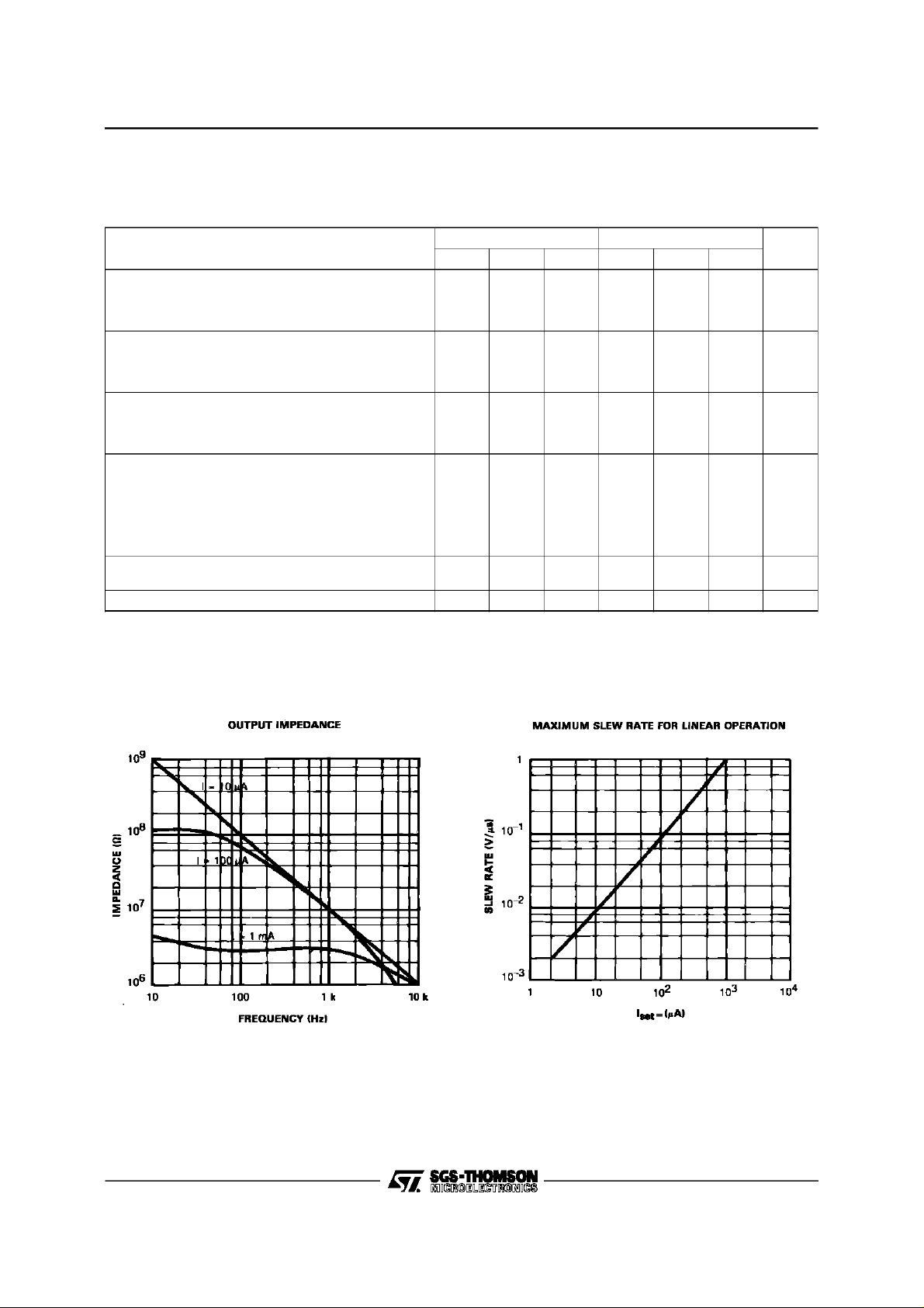
SLEWRATE
At slew rates above a threshold (see curve) the
LM134,LM234, LM334can havea non-linearcurrentcharacteristic.Theslewrateatwhich thistakes
place is directly proportionalto I
dv/dt max. =0.01V/µS ; atI
set
set
.AtI
=10µA,
set
=1mA,dv/dtmax.=
1V/µS.Slew ratesof more than1V/µSdonotdam-
age the circuitnor do they producehigh currents.
THERMAL EFFECTS
Internalheatingcanhavea significanteffecton cur-
rent regulationfor an I
above100µA. For exam-
set
ple, each increase of 1V in the voltage across the
LM134at I
peratureby ≈ 0.4
(I
) has a temperature coefficient of about
set
0.33%/
= 1mA will increase the junctiontem-
set
o
C(in stillair). Theoutput current
o
C. Thusthe changein currentdue tothe increasein temperaturewill be (0.4)(0.33)=0.132%.
This is a degradationof 10 : 1 in regulationversus
the trueelectricaleffects.Thermaleffectsshouldbe
taken into account when d.c. regulation is critical
and I
ishigherthan100µA. The dissipationof the
set
connectionsof CB-97packagecanreducethisthermal effectby acoefficientof more than 3.
SHUNTCAPACITANCE
In certainapplications,the15pFvaluefor theshunt
capacitanceshouldbe reduced :
- becauseofloadingproblems,
- becauseof limitation of the outputimpedance of
the currentsource in a.c. applications.This reduction of the capacitancecan be easily carried outby
addingaFETasindicatedinthetypicalapplications.
The valueof thiscapacitancecanbe reduced by at
least3pFandregulationcan be improved by an orderofmagnitudewithoutanymodificationofthed.c.
characteristics(except for the minimum input voltage).
NOISE
The current noise produced by LM134, LM234,
LM334 is about 4 times that of a transistor. If the
LM134, LM234,LM334 is utilizedas anactive load
for a transistoramplifier, the noise at the input will
increase by about 12dB. In most cases this is acceptable,and a single amplifier can be built with a
voltagegain higher than 2000.
LEAD RESISTANCE
The sense voltagewhich determinesthe currentof
the LM134,LM234,LM334, is less than 100mV.At
this level, the effects of the thermocoupleand the
connectionresistanceshould be reduced by locating the current setting resistor close to the device.
Donot usesocketsfortheICs. A contactresistance
of 0.7Ω is sufficientto decreasethe outputcurrent
by 1% at the 1mAlevel.
SENSINGTEMPERATURE
The LM134, LM234, LM334 are excellent remote
controlled temperature sensors because their op-
erationas sourcesof currentpreservestheir accuracyevenin the caseof longconnectingwires.The
outputcurrentisdirectlyproportionaltotheabsolute
temperaturein degreesKelvinaccording to thefollowing equation.
I
set
(227µV/
=
R
o
K)(T)
set
ThecalibrationoftheLM134,LM234,LM334is simplified by the factthat most of theinitial accuracyis
dueto gainlimitation (slopeerror)andnotan offset.
Gainadjustmentisa onepointtrimbecausetheoutputof thedevice extrapolates to zero at 0
Initial output
c
I
set
b
a
T1 T2 T30°K
b’
a’
Desired output
c’
o
K.
Thisparticularityof the LM134,LM234,LM334 is illustratedin theabove diagram.Lineabcrepresents
thesensorcurrentbeforeadjustmentandline a’b’c’
representsthedesiredoutput.Anadjustmentofthe
gain providedat T2 will move the outputfrom b to
b’and willcorrecttheslopeat thesametimeso that
theoutputatT1and T3will becorrect.Thisgainadjustment canbecarried out by meansof R
set
or the
loadresistorutilized in the circuit.After adjustment,
theslope error should be lessthan1%. A low temperaturecoefficientforR
accuracy. A 33ppm/
isnecessarytokeepthis
set
o
C temperaturedrift ofR
set
will
givean error of 1% onthe slope becausethe resistance follows the same temperaturevariations as
the LM134, LM234, LM334. Three wires are required to isolate R
LM334. Since this solution is not recommended.
Metal-film resistorswith a driftless than20ppm/
from the LM134, LM234,
set
o
arenowavailable.Wirewound resistorscan be utilizedwhen very high stabilityis required.
C
5/10

LM134-LM234-LM334
TYPICAL APPL ICATIONS
Figure 1 : Basic 2-terminal Current Source
Figure 2 : Alternate Trimming Technique
V
i
V
ADJ
V
V
i
Figure 3 : Terminating Remote Sensor for
Voltage Output
R
set
V
i
V
ADJ
V
R
set
R1*
V
i
*For±10% adj ust me nt, se l ect Rset 10%
high and make R1
Figure 4 : Zero TemperatureCoefficient Current
Source
≈ 3Rset
VO=(I
R
set
R
L
6/10
)(RL) = 10mV/OK
set
= 230Ω
= 10kΩ
V
i
V
i
V
V
ADJ
i
ADJ
V
R
set
V
R
set
V
O
R
L
D1
1N 457
V
i
* S elect r at i o of R 1 to R
zero drift i
+
≈ 2I
set
to obtain
set
10
R1*
R
set

LM134-LM234-LM334
Figure 5 : Low Output ImpedanceThermometer
V > 4.8V
i
V
− R
R1
R2
o
16
Ω
where R
R3
V
O
is the equiva-
o
-
pin. This
ADJ
V
C1
R1 = 230Ω ,1% VO=10mV/oK
R2 = 10kΩ,1% Z
R3 = 600Ω
Output im pedance of t h e LM134, LM234, LM334 at the
”A DJ” pin is approximatel y
lent external resist ance connected to the V
negative r esistance can be reduced by a factor of 5 or
more by inserting an equivalent resistor in series with
the output
≤100Ω
O
FIgure 6 : Low Output ImpedanceThermometer
V
i
R1 R2
V
R1 = 15kΩ
R2 = 300Ω
R3 = 100Ω
R4 = 4.5kΩ
C1 = 2.2nF
= 10mV/OK
V
O
Z
≤ 2Ω
O
ADJ
C1
V
R3
R4
V
O
Figure 7 : Micropower Bias
V
R
ADJ
V
R
= 68kΩ
set
UA776
set
1µA
Figure 8 : Low Input Voltage Reference Driver
V
V
i
R1 = 1.5kΩ
V
i
R2 = 120Ω
C1 = 0.1µF
≤ 3mA
I
O
+
≥ Vref + 200mV
V
I
V
O=VZ
i
C1
+64mV (+25oC)
R1
2N2905
V
O
V
LM136
ADJ
V
R2
7/10

LM134-LM234-LM334
Figure 9 : In-line Current Limiter
R
set
ADJ
V
V
i
V
OP AMP
* U se min imum value requi r ed to ensur e
stability of protected circuit
C1*
Figure 10 : Fet Cascading for Low Capacitance
V
i
I
set
Q*
V > 1.2V
DS
V
ADJ
V
V
i
* S elect Q to ens ure at least 1V
across the LM 134, LM234, LM33 4.
V
(1–I
p
set/IDSS
) ≥ 1. 2V
R
set
8/10

PACKAG E MECHANI CAL DATA
8 PINS - PLASTIC MICROPACKAGE (SO)
LM134-LM234-LM334
Dimensions
Min. Typ. Max. Min. Typ. Max.
Millimeters Inches
A 1.75 0.069
a1 0.1 0.25 0.004 0.010
a2 1.65 0.065
a3 0.65 0.85 0.026 0.033
b 0.35 0.48 0.014 0.019
b1 0.19 0.25 0.007 0.010
C 0.25 0.5 0.010 0.020
c1 45
o
(typ.)
D 4.8 5.0 0.189 0.197
E 5.8 6.2 0.228 0.244
e 1.27 0.050
e3 3.81 0.150
F 3.8 4.0 0.150 0.157
L 0.4 1.27 0.016 0.050
M 0.6 0.024
S8
o
(max.)
PM-SO8.EPS
SO8.TBL
9/10

LM134-LM234-LM334
PACKAG E MECHANI CAL DATA
3 PINS - PLASTIC PACKAGE TO92
Dimensions
Min. Typ. Max. Min. Typ. Max.
Millimeters Inches
L 1.27 0.05
B 3.2 3.7 4.2 0.126 0.1457 0.1654
O1 4.45 5.00 5.2 0.1752 0.1969 0.2047
C 4.58 5.03 5.33 0.1803 0.198 0.2098
K 12.7 0.5
O2 0.407 0.5 0.508 0.016 0.0197 0.02
a 0.35 0.0138
Information furnished is believed to be accurate and reliable. However, SGS-THOMSON Microelectronics assumes no responsibility for the consequences of use of such information nor for any infringement of patents or other rights of third parties which
may result from its use. No license is granted by implication or otherwise under any patent or patent rights of SGS-THOMSON
Microelectronics. Specification mentioned in this publication are subject to change without notice. This publication supersedes
and replacesall information previously supplied. SGS-THOMSON Microelectronics products are not authorized for use as critical
components in life support devices or systems without express written approval of SGS-THOMSON Microelectronics.
PM-TO92.IMG
TO92.TBL
1997 SGS-THOMSON Microelectronics – Printed in Italy – All Rights Reserved
SGS-THOMSON Microelectronics GROUP OF COMPANIES
Australia - Brazil- Canada - China - France - Germany - Hong Kong - Italy - Japan - Korea - Malaysia - Malta - Morocco
The Netherlands - Singapore - Spain - Sweden - Switzerland - Taiwan - Thailand - United Kingdom - U.S.A.
10/10
ORDER CODE :
 Loading...