

AUTOMOTIVEDIRECTION INDICATOR
RELAYDRIVER IN CAR DIRECTION
INDICATORS
FLASH FREQUENCY DOUBLES TO INDICATE LAMPFAILURE
DUMP PROTECTION( ± 80 V)
REVERSEBATTERYPROTECTION
L9686
ADVANCE DATA
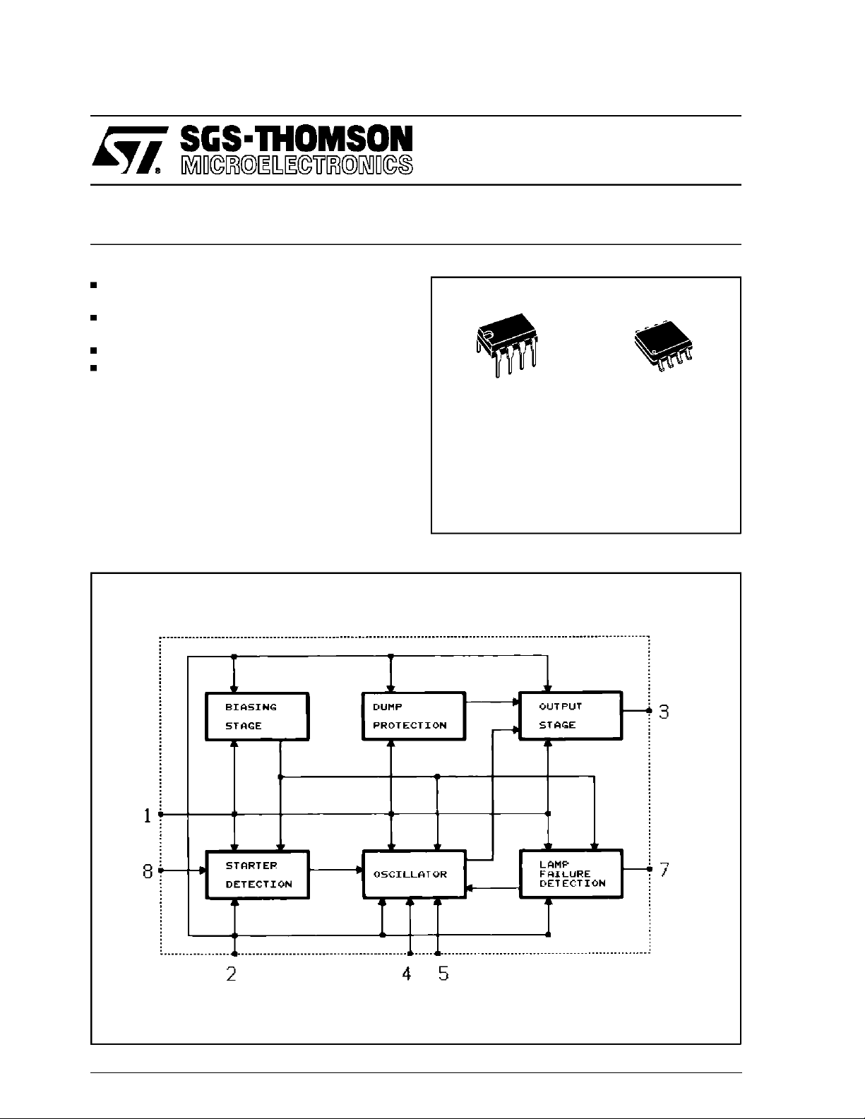
DESCRIPTION
The L9686 is a two frequency oscillator particularly suitable as relay driverfor flashing light control in automotiveapplications.The circuit maybe
alsoused for other warninglamps like ”handbrake
on” etc. The lamp failure detection is given by
doubling the flash repetition frequency. The
L9686 is supplied in minidip 8-leadand SO8plastic packages.
BLOCK DIAGRAM
MINIDIP SO8
ORDERING NUMBERS:
L9686 L9686D
May 1995
This is advanced informationon anew product now in development or undergoing evaluation.Details are subject to changewithout notice.
1/7
L9686
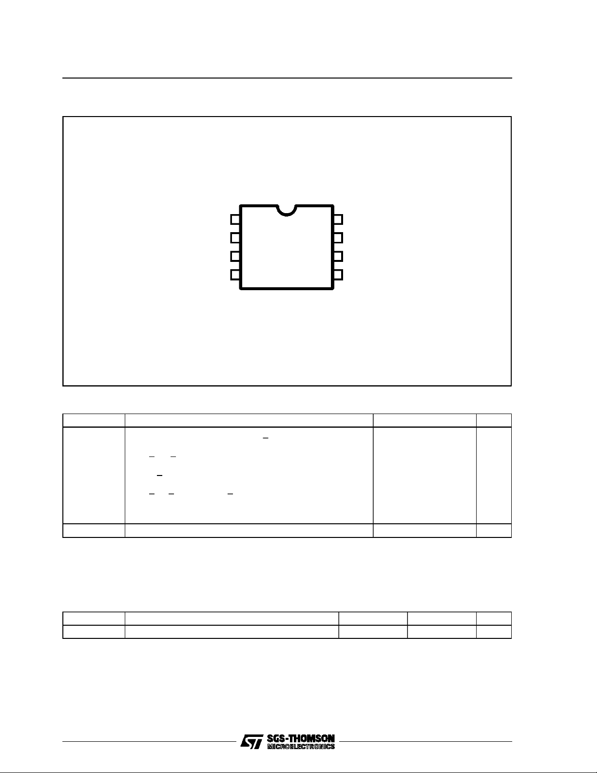
PIN CONNECTION (Top view)
DEVICE GND
+VBATT
OUTPUT
OSCILLATOR
1
2
3
4 OSCILLATOR
D95AT175
7
6
5
STARTER8
FAULT DET.
N.C.
ABSOLUTE MAXIMUMRATINGS
Symbol Parameter Value Unit
Transient Peak Supply Voltage (R3> 220Ω):
LoadDump:
5ms <t
τ
Fall Time Constant = 100ms
f
R
source
Field Decay:
5ms <t
τ
Rise Time Constant = 33ms
r
Low Energy Spike:
t
rise
Junctionand Storage Temperature Range – 55 to 150 °C
rise
> 0.5Ω
fall
=1µs, t
< 10ms
< 10ms, R
= 2ms, R
fall
source
source
> Ω
>10Ω
80
–80
±100
T
j,Tstg
V
S
V
V
V
THERMAL DATA
Symbol Parameter SO8 Minidip Unit
Thermal Resistance Junction-ambient Max. 180 100 °C/W
2/7
R
th j-amb

L9686
ELECTRICAL CHARACTERISTICS (– 20°C<T
<, 100°C, 8V < VS< 18V unless otherwise speci-
amb
fied.)
Symbol Parameter Test Condition Min. Typ. Max. Unit
V
S
V2 – V1 Clamping Voltage see note 1 27 34 V
V2 – V3 Output Saturation Voltage I
R2 Starter Resistance see note 2 3.6 KΩ
K
N
C
T
D.C. Duty Cycle (normaloperation) 45 50 55 %
K
C
DC
I
Q
V
th
Notes :1. This voltage is the threshold used to protect the circuit against overvoltage : if V
2. This is the maximum value for operation.This value must be higher than 1 K Ohms in orderto limit the currentin pin 8 during
3. The external leakage from the blinker unitto ground must be with an equivalentresistor higher than 5,6 KOhmsto avoid para-
4. This temperature coefficient is usefullto compensate thedrift of theexternal timing network(R
5. This threshold is calculated for a 20 m Ohm shunt. The thresholdis dependant of V
Operating Voltage 8 18 V
= 250mA 1.7 V
RL
Oscillator Constant KN(normal
Operation)
Fn = 1/KnRoCo
Osc. Frequency
1.27 1.74
Temperature Coefficient of Kn See Note 3 –1.5 ⋅
10-3
Oscillator Constant K
(lamp failure detection)
Duty Cicle(lamp failure
LF
C
= 1KcRoCo
F
C
Osc. Frequency
0.53 0.74
35 40 45 %
detection)
1,C1
2.2
2.7
3.3
).
Current Consumption Relay off
I
pin 1
Lamp FailureThreshold
(see note 4)
and the voltage across the circuitwill maintain constant increasing the current inthe protective resistorR
dumps. A recommended value for applicationshould be 1,5 KOhms.
sitic operationwhen the switch S
1
is off.
VS=8V
V
= 13.5V
S
S
V
= 18V
R3= 220Ω
V
= 13.5V
S
–20 < T
amb
< 100°C
65 85 95 mV
is > than this threshold, the relay will be on
bat
as the bulb current.
bat
3.9
4.3
4.7
.
3
1/°C
mA
mA
mA
FUNCTIONAL DESCRIPTION
The circuit is designed to drive the direction indicator flasher relay. The application circuit shows
the typical system configuration with the external
components. Its consists of a network (R
1C1
)to
determine the oscillator frequency, shunt resistor
) to detectdefectivebulbs and two current lim-
(R
S
iting resistors (R
) to protect the IC against
2/R3
load dump transients.
The lightbulbs L
2,L3,L4,L5
dicators with the dashboard-light L
, are theturnsignal in-
. The S
6
switch position is sensed across resistor R
and R
by input 8. The flashing cycle is started
lamp
by closing S
: then, after a delay time tdtypically
1
equal to 1.5 ms, the relay is actuated and the pin
3 goes high switching on the corresponding
lamps L
, (or L4,L5). These lamps will flash at
2,L3
the oscillator frequencynot dependingon the battery voltage value (8 - 18 V). The flashing cycle
stops and the circuit is reset to the initial position
when the switchS
is open.
1
The lamp failure detection function senses the
current through the shunt resistor R
of the lightbulbs is defective the voltage drop
1
across R
2
indicatedby doublingthe flashing frequency.
is reduced to a half and the failure is
S
. When one
S
3/7

L9686
Figure1: ApplicationCircuit.
4/7

MINIDIP PACKAGE MECHANICAL DATA
L9686
DIM.
MIN. TYP. MAX. MIN. TYP. MAX.
A 3.32 0.131
a1 0.51 0.020
B 1.15 1.65 0.045 0.065
b 0.356 0.55 0.014 0.022
b1 0.204 0.304 0.008 0.012
D 10.92 0.430
E 7.95 9.75 0.313 0.384
e 2.54 0.100
e3 7.62 0.300
e4 7.62 0.300
F 6.6 0.260
I 5.08 0.200
L 3.18 3.81 0.125 0.150
Z 1.52 0.060
mm inch
5/7

L9686
SO8 PACKAGE MECHANICAL DATA
DIM.
A 1.75 0.069
a1 0.1 0.25 0.004 0.010
a2 1.6 0.063
a3 0.65 0.85 0.026 0.033
b 0.35 0.48 0.014 0.019
b1 0.19 0.25 0.007 0.010
C 0.25 0.5 0.010 0.020
c1 45 (typ.)
D 4.8 5.0 0.189 0.197
E 5.8 6.2 0.228 0.244
e 1.27 0.050
e3 3.81 0.150
F 3.8 4.0 0.15 0.157
L 0.4 1.27 0.016 0.050
M 0.6 0.024
S 8 (max.)
MIN. TYP. MAX. MIN. TYP. MAX.
mm inch
6/7

L9686
Information furnished is believedto be accurate and reliable. However, SGS-THOMSON Microelectronics assumes no responsibility for the
consequences of use of such informationnor for any infringement ofpatents or otherrights of third parties whichmay resultfrom its use. No
license is granted by implication or otherwise under any patent or patentrights of SGS-THOMSON Microelectronics. Specifications mentioned in this publication are subject to change without notice. This publication supersedes and replaces all informationpreviously supplied.
SGS-THOMSON Microelectronics products are not authorized for use as critical components in life support devices or systems without express written approval of SGS-THOMSON Microelectronics.
1995 SGS-THOMSON Microelectronics- All RightsReserved
SGS-THOMSON Microelectronics GROUPOF COMPANIES
Australia - Brazil- France -Germany -Hong Kong- Italy - Japan- Korea -Malaysia - Malta - Morocco - The Netherlands - Singapore-
Spain - Sweden - Switzerland - Taiwan- Thaliand- UnitedKingdom - U.S.A.
7/7
 Loading...