

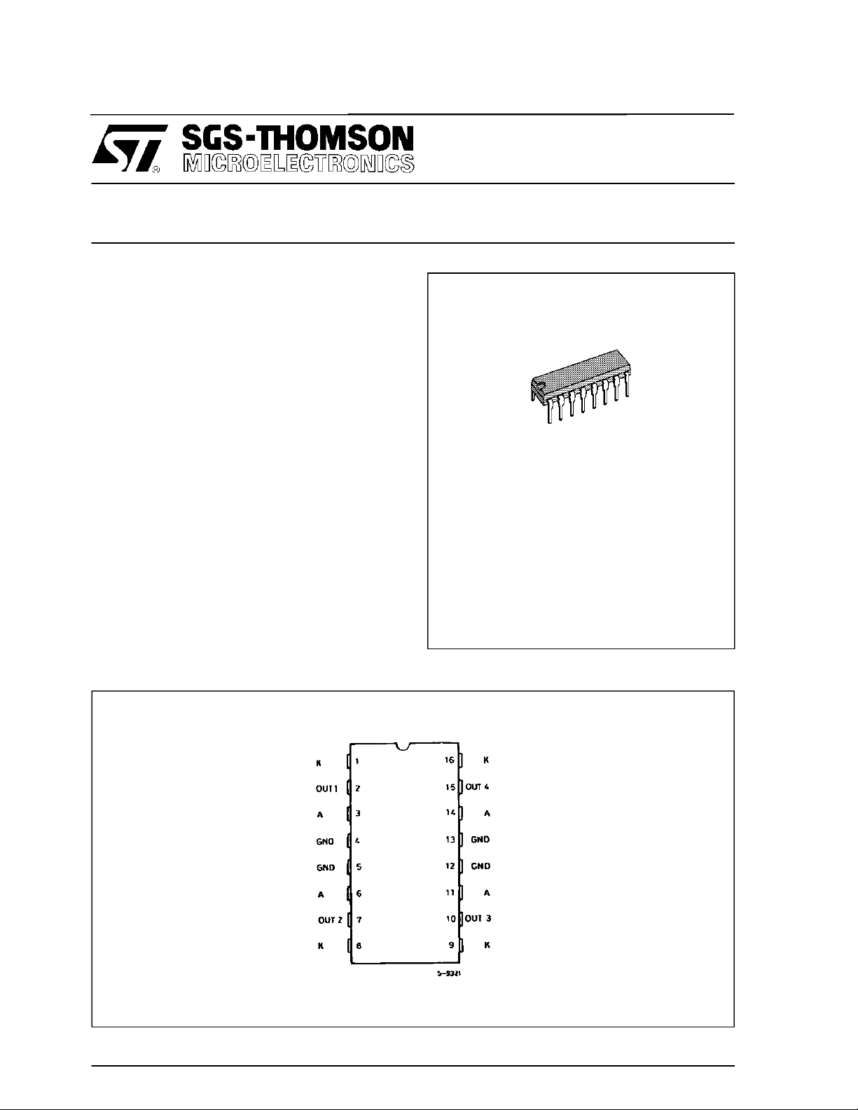
DUALSCHOTTKYDIODE BRIDGE
.MONOLITHIC ARRAY OF EIGHT SCHOTTKY
DIODES
.HIGHEFFICIENCY
.4APEAK CURRENT
.LOWFORWARDVOLTAGE
.FASTRECOVERYTIME
.TWOSEPARATED DIODEBRIDGES
DESCRIP TION
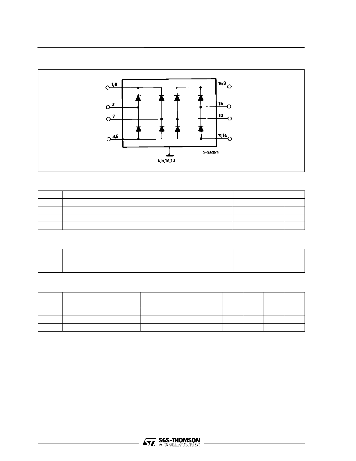
TheL6210isa monolithicICcontainingeightSchottky diodes arranged as two separated diode
bridges.
Thisdiodes connectionmakes this deviceversatile
in manyapplications.
Theyareusedparticularinbipolarsteppermotorapplications,wherehighefficientoperation,duetolow
forwardvoltagedropandfastreverserecoverytime,
arerequired.
TheL6210 is availablein a 16 PinPowerdipPackage(12+ 2 +2) designedforthe0to 70xCambient
temperaturerange.
L6210
N
DIP16
(PlasticPackage))
ORDERINGNUMBER : L6210
PIN CONNECTION (top view)
April1993
1/5
L6210
BLOCK DI AG RAM
ABSOLUTE MAXIMUM RATINGS
Symbol Parameter Value Unit
Repetitive Forward Current Peak 2 A
I
f
V
T
amb
T
Peak Reverse Voltage (per diode) 50 V
r
Operating Ambient Temperature 70
Storage Temperature Range –55 to +150
stg
o
C
o
C
THERMAL DATA
Symbol Parameter Value Unit
R
th j-case
R
th j-amb
Thermal Impedance Junction-case Max. 14
Thermal Impedance Junction-ambient without External Heatsink Max. 65
o
C/W
o
C/W
ELECTRICAL CHARACTERISTICS (Tj=25oC unless otherwise specified)
Symbol Parameter Test Conditions Min. Typ. Max. Unit
V
Note : At forw ard cur r ents of greater than 1A, a parasit ic current of approx imately 10mA may be col lect ed by adiacent diodes.
Forward Voltage Drop If= 100 mA 0.65 0.8
f
= 500 mA 0.8 1 V
i
f
= 1 A 1 1.2
I
f
Leakage Current VR=40V,T
I
L
=25oC1mA
amb
2/5
L621 0
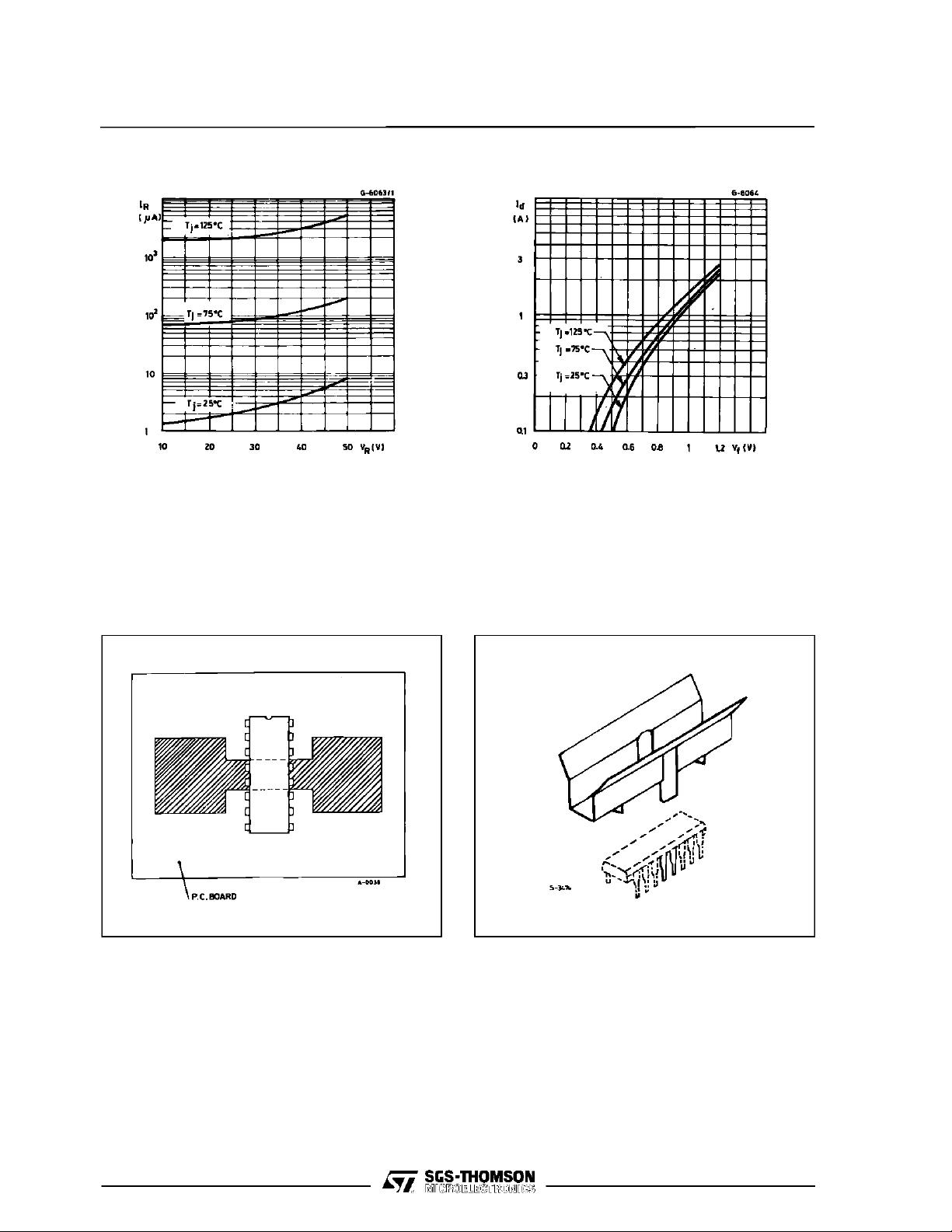
Figure 1 : Reverse Current verus Voltage Figure 2 : Forward Voltage versus Current
MOUNTING I NST RUCTI ONS
o
TheRthj-ambof the L6210canbe reducedby solderingthe GND pins to suitablecopper area of the
printedcircuit boards as shown in figure 3 or to an
externalheatsink(figure 4).Duringsolderingthepin
temperaturemustnotexceed260
ingtime must not be longerthen 12s. Theexternal
heatsinkorprintedcircuit copperareamustbe connectedto electrical ground.
C andthesolder-
Figure 3 : Exampleof P.C. Board Copper Area
which is used as Heatsink
Figure 4 : Example of an External Heatsink
3/5
L6210
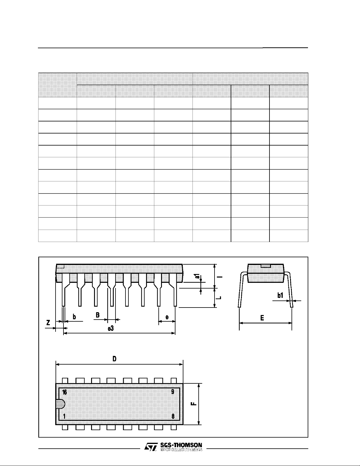
POWERDIP16PACKAGE MECHANICAL DATA
DIM.
MIN. TYP. MAX. MIN. TYP. MAX.
a1 0.51 0.020
B 0.85 1.40 0.033 0.055
b 0.50 0.020
b1 0.38 0.50 0.015 0.020
D 20.0 0.787
E 8.80 0.346
e 2.54 0.100
e3 17.78 0.700
F 7.10 0.280
I 5.10 0.201
L 3.30 0.130
Z 1.27 0.050
mm inch
4/5

L621 0
Information furnished is believed to be accurate and reliable. However, SGS-THOMSON Microelectronics assumes no responsibility for
the consequences of use of such information nor for any infringement of patents or other rights of third parties which may result from its
use. No license is granted by implication or otherwise under any patent or patent rights of SGS-THOMSON Microelectronics. Specifications mentioned in this publication are subject to change without notice. This publication supersedes and replaces all information previously supplied. SGS-THOMSON Microelectronics products are not authorized for use as critical components in life support devices or
systems withoutexpress written approval of SGS-THOMSON Microelectronics.
1994 SGS-THOMSON Microelectronics - All Rights Reserved
Australia - Brazil - France - Germany - Hong Kong - Italy - Japan - Korea - Malaysia - Malta - Morocco - The Netherlands - Singapore -
SGS-THOMSON MicroelectronicsGROUP OF COMPANIES
Spain - Sweden - Switzerland - Taiwan - Thaliand - United Kingdom - U.S.A.
5/5
 Loading...