

GS-D200
GS-D200S
2/2.5A BIPOLAR STEPPER MOTOR DRIVE MODULES
June 1994 1/17
FEATURES
Wide supply voltage range
Full/Half step drive capability
Logic signals TTL/CMOS compatible
Programmable motorphasecurrent andchopper
frequency
Selectable Slow/Fast current decay
Synchronization for multimotor applications
Remote shut-down
Home position indication
DESCRIPTION
The GS-D200 and the GS-D200S are drive modulesthat directlyinterface amicroprocessorto atwo
phase,bipolar, permanent magnet stepper motors.
The phase current is chopper controlled, and the
internal phase sequence generation reduces the
burden of the controller and it simplifies software
development.
TheGS-D200 uses bipolar power outputs whilethe
GS-D200S has powermos outputs to significantly
reduce both commutation and conduction losses.
A further benefit offered by the GS-D200S is the
completeprotection ofthe outputs againstany type
of shorts.
SELECTION CHART
Type
Ordering
Number
Phase
Current
(A)
Voltage
Drop
(V)
Supply
Voltage
(V)
GS-D200
1.0 nom.
(0.5 to 2.0)
4.1 max.
10 to 46
5.0±5%
GS-D200S
2.0 nom.
(0.5 to 2.5)
2.5 max.
12 to 40
5.0±5%
2/17
ABSOLUTEMAXIMUM RATINGS
Symbol Parameter Value Unit
V
s
DC Supply Voltage (pin 18)
GS-D200
GS-D200S
48
42
V
V
V
ss
DC Logic Supply Voltage(pin 12)
7V
T
stg
Storage TemperatureRange
– 40 to +105 °C
T
cop
Operating Case Temperature Range
– 20 to +85 °C
ELECTRICAL CHARACTERISTICS (TA=25°C and VS=24V unless otherwise specified)
Symbol Parameter Test Conditions
Value
Unit
Min Typ Max
I
s
Quiescent Supply Current Pin 18
20 mA
I
ss
Quiescent Logic Supply Current Pin 12 Vss=5V
60 mA
V
i
Input Voltage
Pin
3,4,6,7,10,1 1
Low
High
2
0.8
V
ss
V
V
I
i
Input Current
Pin
3,4,6,7,10,1 1
Vi=Low
Vi=High
0.6
10
mA
µA
V
sat
Source/Sink Saturation Voltage(GS-D200)
Pin
14,15,16,17
Io=1A
1.8 V
V
sat
Source/Sink SaturationVoltage(GS-D200S)
Pin
14,15,16,17
Io=2A
1.8 V
I
oL
Current Limit Intervention GS-D200S
5A
f
c
Chopper Frequency
17 kHz
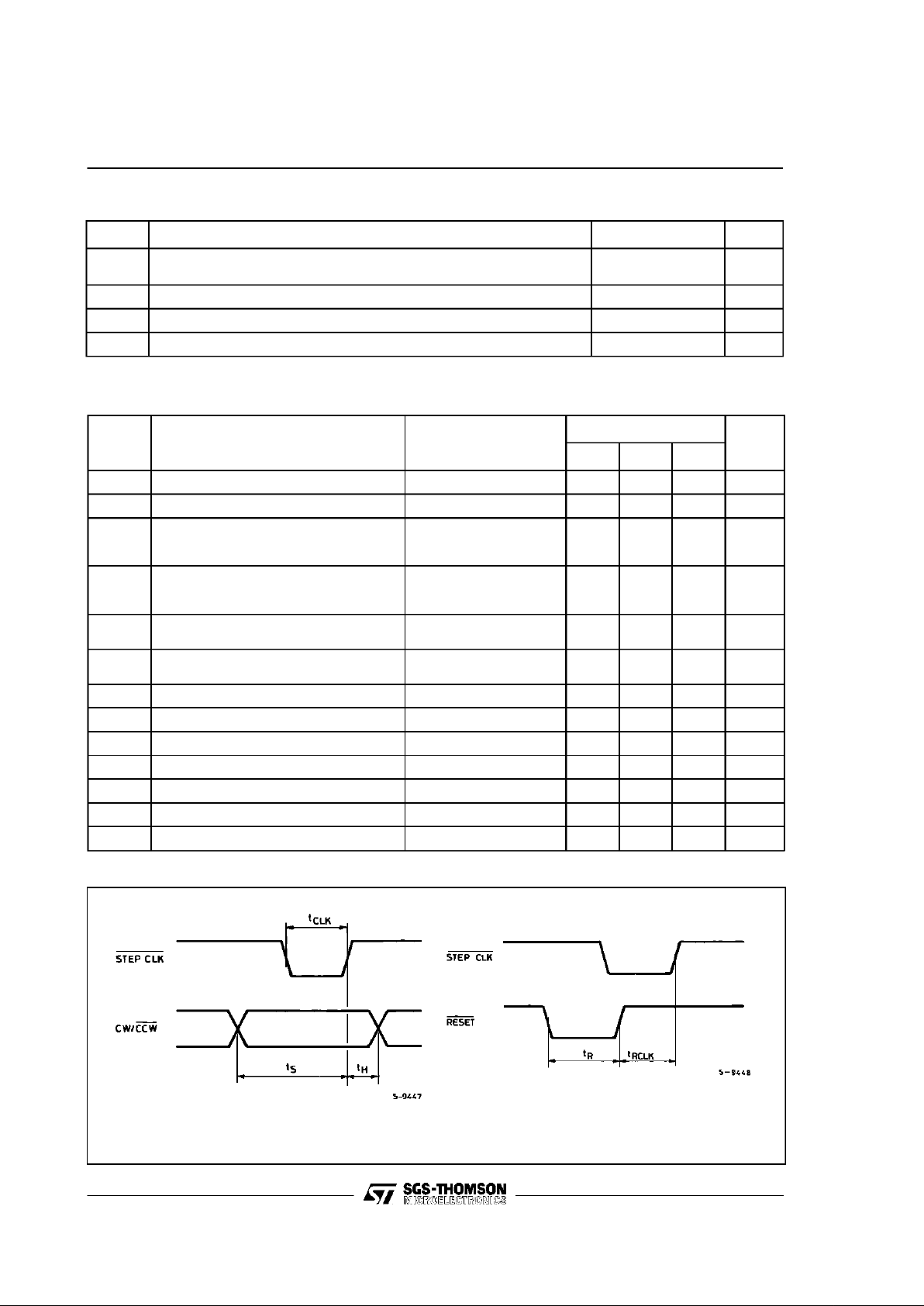
t
clk
Stepckl Width Pin6 (Seefig. 1)
0.5 µs
t
s
Set Up Time
”1 µs
t
h
Hold Time
”1 µs
t
r
Reset Width
”1 µs
t
rclk
Reset to Clock Set Up Time
”1 µs
Figure 1: Signals Timing
GS-D200/GS-D200S
3/17
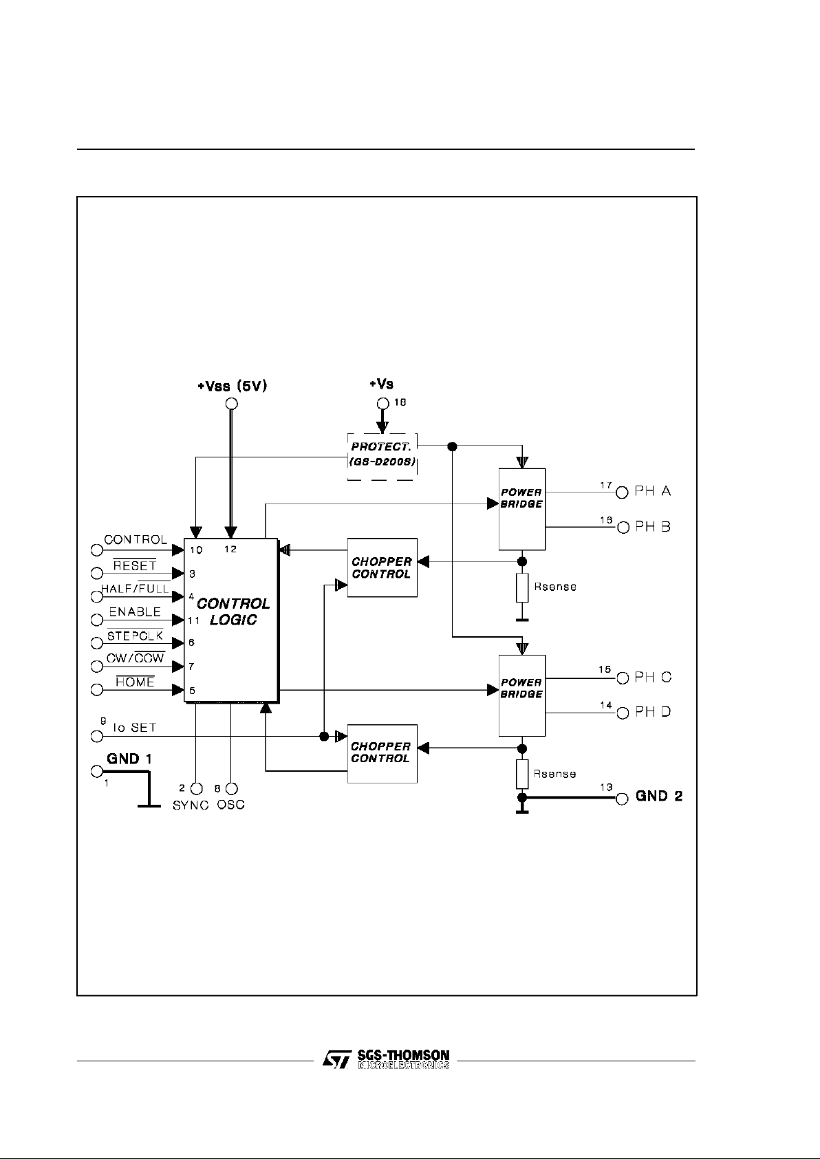
Figure2: GS-D200 and GS-D200SBlock Diagram
GS-D200/GS-D200S
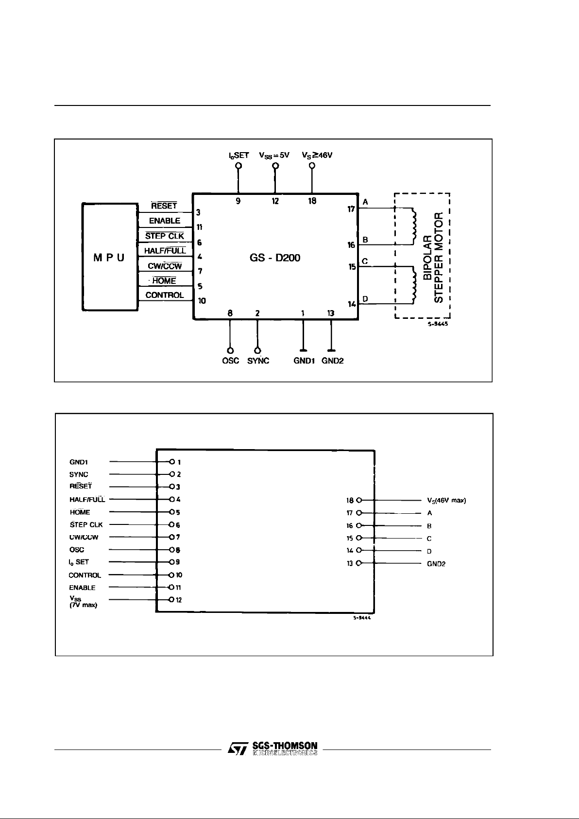
Figure 3: GS-D Modules Typical Application
4/17
Figure 4: GS-D200 and GS-D200S Connection Diagram (Topview)
GS-D200/GS-D200S
5/17
PIN DESCRIPTION
Pin Function Description
1
GND1 Return path for thelogic signals and 5V supply.
2
Sync
Chopper oscillatoroutput.
Several modules can be synchronized by connecting together all Sync pins. This pin can
be used as the input for an external clock source.
3
Reset
Asynchronousreset input. An active low pulse on this input preset the internal logicto the
initial state (ABCD=0101).
4
Half/Full
Half/Full step selection input.
When high or unconnectedthe halfstep operation is selected.
5
Home
When high, this output indicates that the internal counteris in its initial state (ABCD=0101).
This signal may be usedin conjunctionwith a mechanical switch to ground or with open
collectoroutput of an optical detector to be used as a systemhome detector.
6
Stepclk The motor is movedone stepon therisingedge of this signal.
7
CW/CCW
Direction controlinput. When high orunconnected clockwiserotation is selected. Physical
direction of motor rotationdepends also on windings connection.
8
Oscillator
The chopper oscillatortiming, internally fixed at 17kHz, can be modified by connecting a
resistor between this pin and Vssor a capacitor between this pin and Gnd1.
The oscillatorinput mustbe groundedwhen the unit is externally synchronized.
9
I
oset
Phase current settinginput. Aresistor connectedbetween thispin and Gnd1 or Vss,
allows the factory setted phasecurrent value (1Afor GS-D200and 2Afor GS-D200S) to
be changed.
10
Control
Logic input thatallows the phase current decay mode selection. When high or
unconnected the slow decay is selected.
11
Enable
Module enable input. When low this input floats the outputs enabling the manual
positioning of the motor.Must be LOW duringpower-up and down sequence,HIGH during
normal operation.
12
V
ss
5V supply input. Maximum voltage must not exceed 7V.
13
GND2 Return path for the power section.
14
D D output.
15
C C output.
16
B B output.
17
A Aoutput.
18
V
s
Module and motor supply voltage.
Maximum voltage must not exceed the specified values.
GS-D200/GS-D200S
6/17
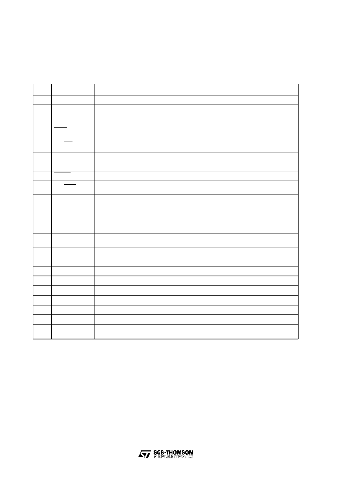
BIPOLAR STEPPER MOTOR BASICS
Simplified to the bare essentials, a bipolar permanent magnet motor consists of a rotating-permanent magnet surrounded by stator poles carrying
the windings (fig. 5).
Figure 5: Simplified Bipolar Two Phase Motor
Bidirectional drive current is imposed on windings
A-B and C-D andthe motor is stepped by commutating the voltage applied to the windings in sequence. For a motor of this type there are three
possible drive sequences.
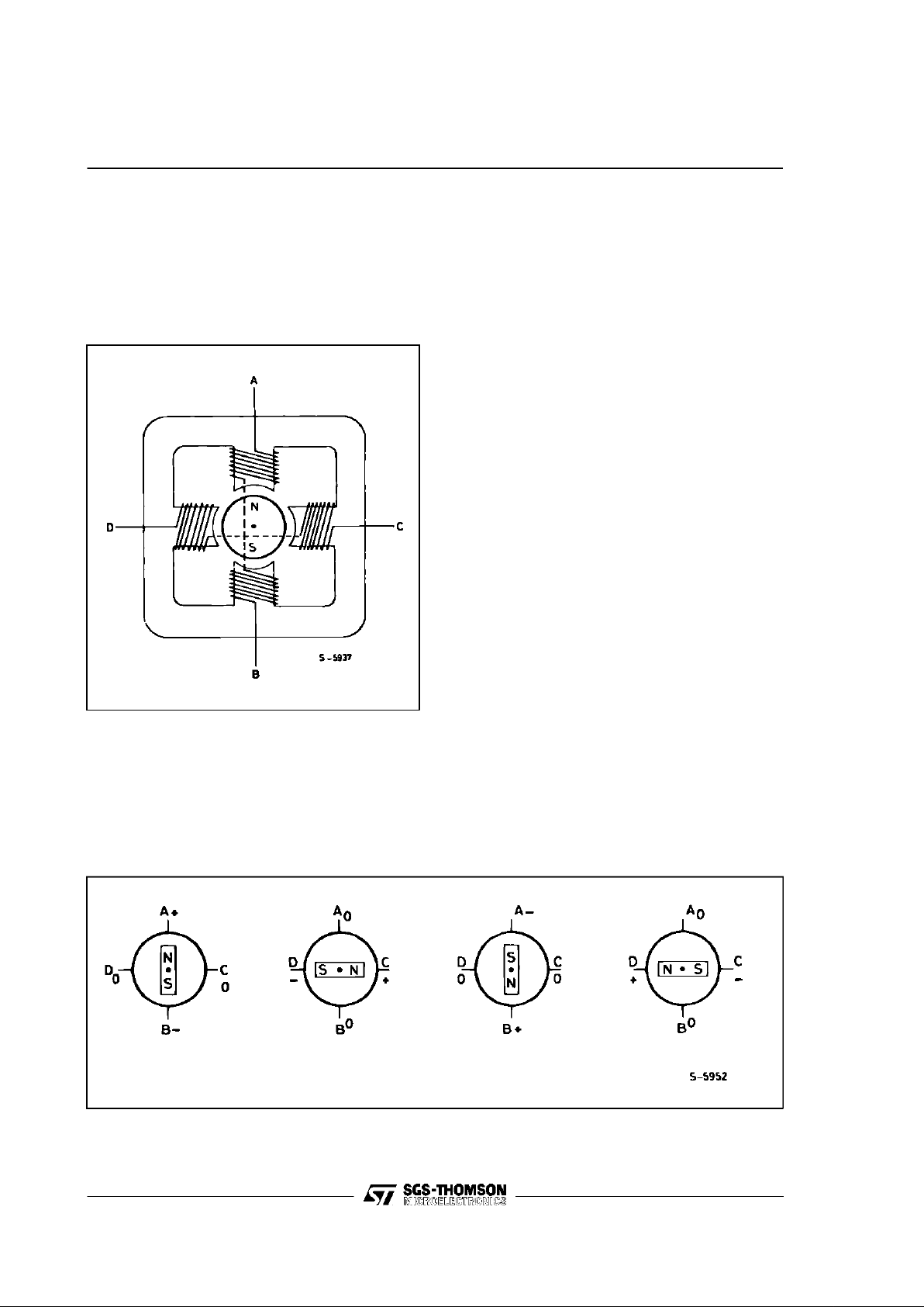
Figure 6: One-Phase-on (Wave Mode) Drive
One-Phase-on or Wave Drive
Only one winding is energized at any given time
according to thesequence :
AB - CD - BA - DC
(BAmeans that the current is flowing from Bto A).
Fig.6 showsthe sequence for a clockwiserotation
and the corresponding rotor position.
Two-Phase-on or NormalDrive
Thismode givesthe highesttorque sincetwo windings are energized at any given time according to
the sequence (for clockwiserotation).
AB & CD ; CD & BA; BA & DC; DC & AB
Fig. 7 shows the sequenceand the corresponding
positionof the rotor.
Half Step Drive
This sequence halves the effective step angle of
the motorbut gives aless regular torque being one
winding or two windings alternatively energized.
Eight steps are required for a complete revolution
of the rotor.
The sequence is:
AB ; AB& CD ; CD ; CD & BA; BA; BA& DC;
DC ; DC& AB
as shown in fig. 8.
By theconfigurations of fig. 6, 7,8 the motor would
have astep angle of90 ° (or 45° inhalf step). Real
motorshave multiplepoles pairsto reducethe step
angle to a fewdegrees but the number of windings
(two) and the drive sequence are unchanged.
GS-D200/GS-D200S
 Loading...