

Page 1
INTELLIGENT STEPPER MOTOR CONTROLLERS
FEATURES
Absolute and incremental positioning
Up to 999,999 step permove
Speed range to 10,000 steps/s
Ramp lenght to 999 steps
Single unregulated supply voltage
Index and velocity mode
Automatic and Home positioning
Loops and Delay execution
Conditional start and stop
Status feedback to the host
RS232 communication port
Point to point and Multipoint protocol
Closed loop operation
Counter preset (GS-C200Sonly)
Jump to (GS-C200S only)
Jump to on-condition (GS-C200Sonly)
Initialization during execution (GS-C200Sonly)
Auxiliary output voltages +5V, ± 12V
GS-C200
GS-C200S
DESCRIPTION
The GS-C200 and GS-C200Sarepowerfulstepper
motor control modules that interface every power
sequencer/driver available on themarket.
A sophisticated hardware and an easy to learn
programming language result in minimal development and debugging time of motion control systems. The modules are supported by dedicated
software thatincludes both anon-screeneditorand
a debugger that greatly improve the module ease
of use.
The instruction setscompriserespectively 25 (GSC200) and 29 (GS-C200S) different commands
ABSOLUTE MAXIMUM RATINGS
Symbol Parameter Value Unit
V
T
T
DC SupplyVoltage
s
Storage Temperature Range
stg
Operating Temperature Range
op
Humidity (non condensing)
which can be executedeither underhost control or
in a stand alone environment. An on board EEPROM is used for program saving and retrieving.
The availability of three User inputs and three
programmable Useroutputs, eachof which can be
tested or set under program control,assures tothe
designer ahighlevelofsystempowerand flexibility.
42 V
–40to+85 °C
0to+50 °C
0to90 %
June 1994 1/31
Page 2

GS-C200/ GS-C200S
ELECTRICALCHARACTERISTICS (TA= 25C and Vs=24V unlessotherwise specified)
Symbol Parameter Min Typ Max Unit
V
V
t
cpw
t
rpw
DC SupplyVoltage
s
Quiescent Supply Current
I
s
Logic Input Voltage
V
i
(TTLcompatible)
Logic Output Voltage
o
(TTLcompatible)
Clock Pulse Width
Reset Pulse Width (Internal)
Low
High
Low
High
12 40 V
80 mA
2
2
0.8
5
0.8
5
5 µs
500 µs
V
V
V
V
MOTION CHARACTERISTICS
SPEED RANGE 10 to 10000 steps
SPEED RESOLUTION 10 steps
RAMP LENGHT 1 to 999 steps
RAMP RESOLUTION 1 step
POSITIONINGRANGE(C200)
(C200S)
SINGLE MOVEMENTRANGE 1 to 999999 steps
POSITIONINGRESOLUTION 1 step
POSITIONINGREPEA T IBILITY +/– 0 step
PROGRAM STORAGE
CAPABILITY
0 to 9999999
– 8388608 to + 8388607
119bytes
COMMUNICATION PORT CHARACTERISTICS
SIGNALLINES 3 (TxD,RxD, GND)
BAUD RATERANGE 110 to 9600
FORMAT 1 Start Bit
7 Data Bit
2 Stop Bit
Odd parity
STORAGECAPACITY
MINIMUM NUMBER OF COMMANDS 30
MAXIMUM NUMBER OF COMMANDS 45
2/31
Page 3
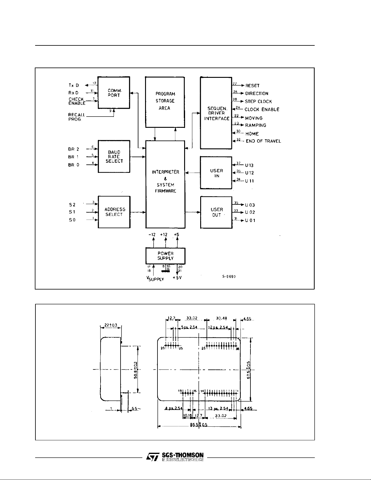
Figure 1. Block Diagram
GS-C200/ GS-C200S
CONNECTION DIAGRAM AND MECHANICALDATA
Dimensions in mm.
Bottomview
3/31
Page 4

GS-C200/ GS-C200S
PIN DESCRIPTION
Pin Function Description
SEL0 Protocol/addressLSB select input
1
SEL1 Protocol/addressSSB select input
2
SEL2 Protocol/addressMSB select input
3
BR0 Baud rate LSB select input
4
BR1 Baud rate SSB select input
5
BR2 Baud rate MSB select input
6
CHS Checksum enable input
7
GND Ground
8
REC Program autorecall input
9
10
11
12
13
14
15
16
17
18
19
20
21
22
23
24
25
26
27
28
29
30
31
32
33
34
35
36
37
38
Notes: 1– Maximum available current is 10mA
RXD RS232 received data input
TXD RS232 transmitteddata output
TXPD Transmitted data pull-down resistor
RDY Status logic output
–VSL Unregulated –12V supplyoutput (note 1)
+VSL Unregulated +12V supply output (note 1)
V
s
V
s
GND Ground
5V 5V Auxiliary output(note 2)
5V 5V Auxiliary output(note 2)
MOV Motor moving logicoutput
RAMP Motor ramping logicoutput
ENABLE Stop enable logic input
DIR Direction selection logic output
RESET Power driver Reset logic output
CLOCK Step clock logic output
HOME Home position logic input
UO1 User 1 logic output
EOT End of travel switch logic input
UO2 User 2 logic output
UI1 User 1 logic input
UO3 User 3 logic output
UI2 User 2 logic input
UI3 User 3 logic input
GND Ground
2 – Maximumavailable current is 100mA
Must be connected to pin 8
Supply voltage input
Supply voltage input
Not connected
Not connected
4/31
Page 5

GS-C200/ GS-C200S
The various signals that characterize the GS-C, their function and the active level are described in detail
in the following:
Pin Function
1-2-3
4-5-6
7
8
9
10
11
12
13
14
15
16
17 - 18
19
20 - 21
22
23
24
25, 29
26
27
The SEL0 (pin1), SEL1 (pin2) and SEL2 (pin3)inputs are used to select the communicationprotocol and
the module address. They have an internalpull-up and when unconnected they are at the 1 logic level.
The BR0 (pin4), BR1 (pin5) and BR2 (pin6)inputs are used to select the Baud rate of the
communication port. They have an internal pull-up and when unconnected they are at the 1 logic level.
The CHS checksum generationconditioning input enables the user to include or exclude the checksum
character from thedata exchange string. A ”zero” logic level appliedto this input disables the control and
the generation of the checksumcharacter thus allowing the GS-C to be connectedto a video terminal.
This pin is the common terminal for all logic signals and for the power supply return path.
The REC RecallProgram Enable input pin, when brought to ”zero”, enables the automatic recallof the
program stored inthe EEPROM and itsimmediate execution.
This pin is for testingpurpose only and itmust be grounded for normaloperation.
The RxD inputof the serial communication port is used by the module to receive commands from the
Host Computer. The input logic levels are compatible with the RS232 and V24 standards.
The TxD output of the serial communicationport is used by the moduleto send data to the Host
Computer. The logic levels of this output are compatiblewith the RS232 and V24 standards.
The TxPD Transmitted data pull-down resistorpin must always be connectedto the TxDoutput (pin 12)
when the Point-to-Point protocol is used. Whenthe Multipoint protocol is selected, this pin mustbe left
open on all modules except the chainterminator unit, in orderto avoid the TxD output overload.
The RDY hardware statusoutput (opencollector) signal pin is used as the controllerstatus flag. RDY
assumes a ”zero” logic level when a command or a program is in execution
–12V unregulatedoutput. A maximum of 10mAcan be sinked from this pin.
+12V unregulatedoutput. A maximum of 10mA can be sinked from this pin.
Module supply input. For correctoperations a supply voltage ranging from 12 to 40 Volt is required.
See pin 8.
5 Voltregulated output, available either for the Sequencer-Driver logic section or for a custom interface
logic supply. The maximum current that can be sinked from this pin is 100mA.
The MOV Motor moving output becomes the logic level ”one” when the GS-C is executing a movement.
This output can be used to program the phase current level when the motion is runningat a levelhigher
than for the rest condition.
The RAMP Ramp in execution output is rised to the logic level ”one” when the GS-Cis executing an
acceleration or a decelerationramp. Thisoutput can be used to program the phase current level when
the motion is ramping at a level higherthan for the rest or slewing condition.
The ENABLE input pin allowsthe user to control the Step clock logic output to avoid the motorbeing
stepped if the previous step was not correctly executed. A ”zero” logic level appliedto this pin stops the
generation of the step pulses. Thisinput canbe used to stop the system when an emergency occurs,to
execute the motion according to externally generated timing, or to implementa closed loop control
system.
Not connected.
The DIR Direction selectionoutput isused to inform the Sequencer-Driveron the directionof rotation.
The logic level ”one” determines a clockwise rotation, but of course the rotationdepends on the motor
phases connectionto the Sequencer-Driver.
The RESET Power driver Reset output is brought to the ”zero” logic state for 400µs when the unit is
powered-on, or when the GS-C receivesthe ”Initialize position counter” command. Thisoutput is
normally used to assurethe correctstart-up of the Sequencer-Driver or any other external custom logic.
5/31
Page 6
GS-C200/ GS-C200S
Pin Function
The CLOCK Step clock output is used to informthe Sequencer-Driver to perform a step. The direction
28
30
31
32
33
34
35
36
37
38
(clockwise or counterclockwise) is defined by the logic status of the DIR output. In steady conditions, the
CLOCK is at the ”one” logic level, and the step is represented by a negative going pulsewith a 1.7µs
duration.
The HOME Home position input allowsthe systemto find itsreference point. This input can be driven by
a mechanically activated contact indicating the ”zero” position. It is normally used togetherwith the EOT
End-of-travel signal.
The UO1 User output 1 is intended for user purposes. Thestatus of this output can be set and cleared
under program control and it can be used forvarious functions. It is normally used for the control of
externaldevices, the selectionof the Sequencer-Driveroperating mode, or the synchronization of
complex movements.
The EOT End-of-travel inputallows, in combination with the HOME input, the correct mechanical
initialization of the system. For this purpose it must be brought to the ”zero” logic level when the system
reaches the run end position.
The U02 User output 2 is intended for user purposes. See pin 31 description.
The UI1 User input is intended for user purposes. The status of this input can be readby the Host
Computer or tested duringthe program execution, and used to condition the start of a movement,the
execution of a specific portion of a program (GS-C200S only), or any other similar operation.
The UO3 User output 3 is intended for user purposes. See pin 31 description.
The UI2 User input 2 input is intended for user purposes. See pin 34 description.
The UI3 User input 3 input is intended for user purposes. See pin 3 and pin4 description.
See pin 8.
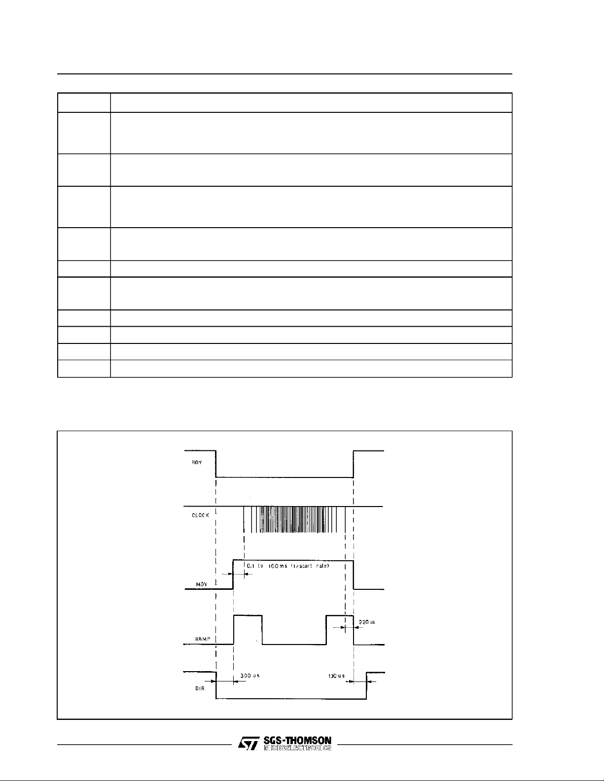
Figure 2. GS-C Timing Diagram
6/31
Page 7

GS-C200/ GS-C200S
S.I.M.P.L.E. Interpreter Command and Functions
(SGS-THOMSONInteractive Stepper Motor Programming Language and Executor)
Command
Ax
Cx
Dxxx
E
F
f+/–xxxxxxx
G+/–xxxxxxx
g(+/–)
g(+/–)x
H(+/–)
Ix
jx
jcy,x
K
Lx
M
P
Po
Px
Q
Rxxx
Sxxx
Txxx
Ux
Vx
X
Wx
Z
+/–xxxxxx
Byte
Length
2
2
2
–
–
4
4
4
4
–
2
2
2
–
2
–
–
–
–
–
4
4
4
2
–
–
2
–
4
Function
Activate the specified(x) Useroutput.
Clear the specified (x) User output.
Delay for the specfied number (xxx) of tenth of second.
Startexecutingthe program currently stored into RAM memory.
Feedback the GS-C status (i.e.Ready orBusy).
Preset the position counter to the specifiedabsolute value (C200S).
Go to the specified target position(C200S).
Move the motor indefinitelyin the specified direction.
Move the motor in the specified directionuntil the specified(x) input is brought to zero.
Find Home position moving clockwise (+), or moving counterclockwise (–).
Initialize the position counter (x=1), the user outputs (x=2), or both (x=3).
Jump to memory location (x). Location (x)ranges between 0 and 118(C200S).
Jumpto memorylocation (x) if thebinaryvalue of the user inputs matches (y) value (C200S).
Kill the program inexecution.
Loop for the specified(x) number of times.
Transfer the RAM memory content to EEPROM.
Enter the programming mode (C200).
Enter the programming mode (C200S).
Exit the programming mode (C200S).
List to the host the program currently in RAM memory.
Set the Ramp length to the specified (xxx) value.
Set the start-stopspeed to the specified (xxx) value.
Set the slewrate speedto the specified (xxx) value.
Execute the program until the specified (x) user input isbrought to a low level.
Read back the current position (x=1) or the userI/O status (x=2).
Transferthe programfrom EEPROM to RAM.
Wait until the specified(x) user inputis raised to a logicone level.
Stop through a deceleration ramp.
Move clockwise (+) or counter-clockwise (–) for the specified (xxxxxx) number of steps.
7/31
Page 8
GS-C200/ GS-C200S
GS-C200 AND GS-C200SDESCRIPTION
The increasing popularity of microprocessors and
theirvery lowcost,havecontributed to afast growth
of stepper motors usage in a large numbers of
application previously covered by more complex,
bulk and expensive DC motors servo loops. The
GS-C200 and the GS-C200S modules have been
conceived to help the industrial designer in designing the stepper motor applications based on microprocessor control.
Thesemodules are programmable intelligentstepper motor controllers that coordinate highly complex movements and sequential operations. This
capability is performed through the integration of
sophisticated hardware and an easy to learn and
very functional and powerful programming language.
Thanks to this high level programming language,
the power of the instruction set and the ability to
condition an d cont r ol the program executi on
throughtheUSERinputsandoutputs,the GS-C200
and GS-C200S drastically reduce the design time
and start-up manufacturing phase of very complex
systems. The GS-C200S offers an advanced and
powerful instruction set that includes also the conditional jump which allows for more efficient program-ming. TheGS-C200,the GS-C200Sand their
companion modules, the GS-D200 and the GSD200S, can be used to drive in chopped mode of
bipolar stepper motor with a 2/2.5A maximum
phase current rating.
The two modules (GS-C and GS-D) are available
also on a single Eurocard board named respectively GS-DC200, GS-DC200S and GS-DC200SS
according to the variousmodules combination (see
the relevant data sheet). In the following the modules will be generically named GS-C. The specific
module part number will be used when the feature
is unique to that module.
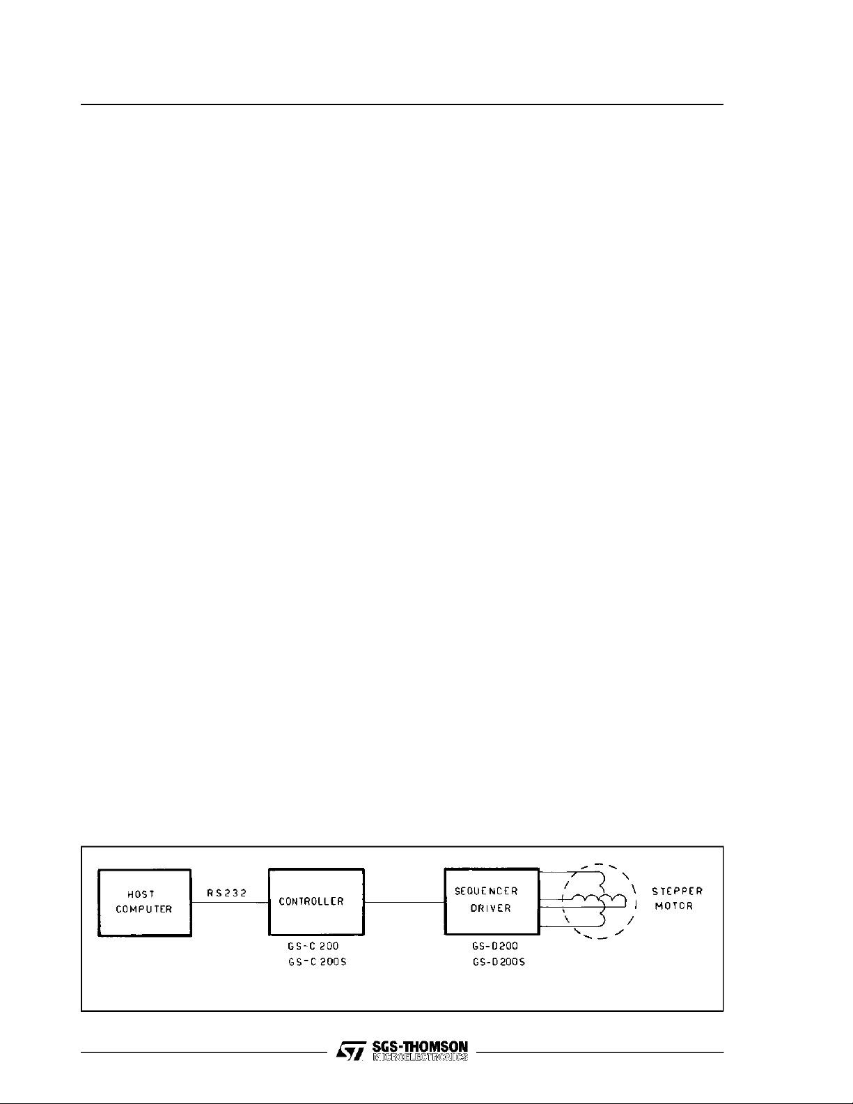
A MOTION SYSTEMARCHITECTURE
A complete motion system controlled by a host
computer is normally configuredas per fig. 3.
The GS-C logical and functional architecture is
shown in fig. 1 and it includes the following basic
blocks:
– Interface to the Host Computer via an RS232
communication port.
– Addressand baudrate selection.
– Interface to the Sequencer-Driver (in particular
but not exclusively, to the GS-D200 or GS-
D200S)via 5 outputand 3 input lines
– Command Interpreter and Executor.
– Program storage area
– Power Supply.
The above mentioned functions are performed by
the GS-Cwithout the addition of anyexternal component, and the module flexibility is further enhanced by the use of only one unregulated supply
voltage that can be the same used to supply the
Sequencer-Driver (from 12V up to 40V).
Commands are sent to the module bya Host Computer or by a simple video terminal during the
programming/debugging phase through an RS232
serial port. They are interpreted and validated by
the command interpreter and executed through the
Sequencer-Driver interface.
Command execution can be conditioned and controlled by the statusof the USER IN-OUTinterface.
Aprogram storagearea has been added to permanently store a program in an on-board EEPROM;
this is particulary beneficial to obtain a low cost
stand-alone controller that doesnot need any connection to an external computer or to store programs f requ ent ly used in complex motion
sequencies thus reducing the host computer burdenand speeding up the systemprocessing.
Particular attention hasbeen given to the simplicity
of the instruction setto allowan easydesign of the
system to those designers that are notvery familiar
with microprocessor software and programming.
In thefollowing a detailed description ofthe various
functional blocks is given.
Figure 3. A Motion System Block Diagram
8/31
Page 9
GS-C200/ GS-C200S
INTERFACE TO THE HOST COMPUTER AND
DATAPROTOCOL
The interface to the Host Computer is through an
RS232or V24 serial communication port.
Baud Rate Programming
The Baud rate is programmed between 110 and
9600 bit/secby using the BR0,BR1and BR2inputs
according to the following table:
BR0 (p4) BR1 (p5) BR2 (p6) Baud Rate
0 0 0 9600
1 0 0 4800
0 1 0 2400
1 1 0 1200
0 0 1 600
1 0 1 300
0 1 1 150
1 1 1 110
This settingis obtained byconnecting the pins 4,5,
and 6to ground (0 status) or by leaving themopen
(1 status). The communication port does not use
any control line but just the transmit and receive
signals. The host computer must handle the data
excange in the proper way.
Module Address Programming
The communication protocol can be either Point to
Point or Multipoint. In the first case a single communication line is required for each module, while
in the latter more than one module (up to seven)
can share the same communication line.
The Multipoint protocol as well as the peripheral
device address are selected through SEL0, SEL1
and SEL2 inputs. The Point-to-Point protocol is
selectedby connecting all the SELinputs to the 5V
outputpin (pin 20) or by leaving themopen.
The following table defines the protocol and the
address setting:
When the multipoint connection is chosen, the address ofeach module isobtained by connecting the
various SEL pin (1, 2, 3) to ground (0 status)or by
leaving them open (1 status).
The basic difference between the two protocols is
represented by the sytemwiring complexityandthe
data throughput. The Point-to-Point offers the
higher throughput data rate but it requires a connecting cable for each unit, while the Multipoint
minimizes the connecting cables but at reduced
throughput rate.When thislatterprotocolis chosen,
the command must always be preceeded by the
address of the unit.
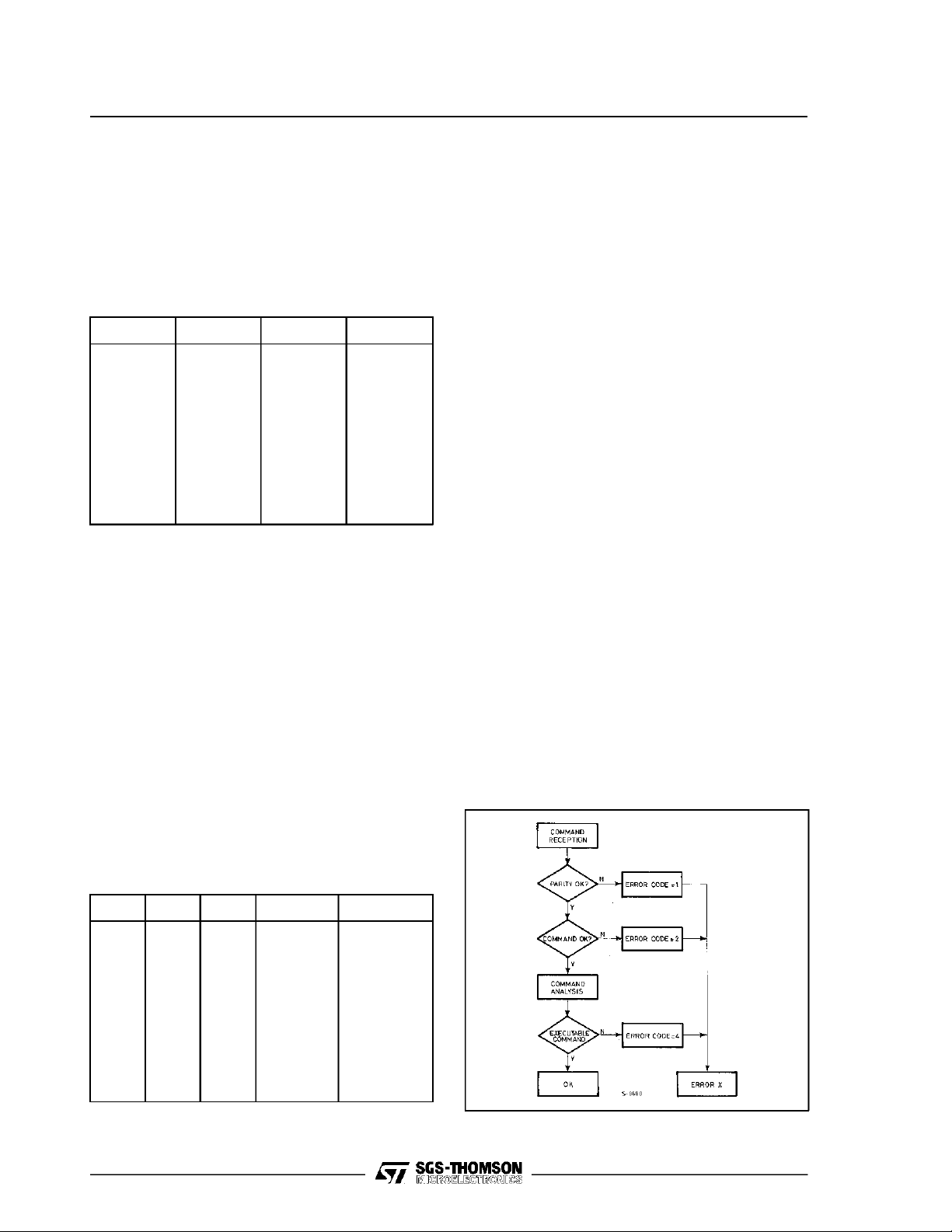
Data Exchange Protocol
The dialogue is always driven by the Host Computer which sends the string containing the command or the request to be implemented. The GS-C
module stores the instruction sent by the Host and
then it checks if the string has been correctly received by analyzing the parity bit. It then analyzes
the consistencyof the receivedinstructions by verifying the presence and correctness of the argument, andfinally,it checkswhether therequest can
be processed or not (for example, an attempt to
move outside the system limits, etc.) reporting to
the Host the analisysresult. If no error is detected,
the GS-C replies to the Host by a ”Y” message. In
case oferror, the messagewill be ”Error X” requesting the Hostto send themessage again orto modify
some parameters ofthepreviousmessageto fix the
error detected by the GS-C. The actual value of X
(see fig. 4 and error code table) gives the Host the
information on the type of detected error. The procedure implemented for the dialogue with the Host
is shownon the flowchart of fig. 4.
Figure4. Controller-Host Dialogue Flowchart.
SEL2 SEL1 SEL0 Address Protocol
0 0 0 7 Multipoint
1 0 0 6 Multipoint
0 1 0 5 Multipoint
1 1 0 4 Multipoint
0 0 1 3 Multipoint
1 0 1 2 Multipoint
0 1 1 1 Multipoint
1 1 1 – Point-to-Point
9/31
Page 10
GS-C200/ GS-C200S
The general format of a command string is the
following:
ADDRE SS CO MMAND ARGU MENT CHEC KSU M CAR.RETURN
The Address must be the firsttransmitted characterand it is present only ifthe Multipoint protocol is
used (at least oneof SEL0, SEL1, SEL2 is different
from zero).
The Command is the second character(s) of the
string, inthe Multipoint protocol, but it becomes the
transmission opening character when the Point-toPointprotocol is used (SEL0, SEL1 and SEL2 = 0).
TheArgument, ifrequired,isspecified immediately
after the command and its length depends on the
command type.
The Checksum character verifies the correctness
of the received string; itsvalue isdetermined bythe
sum of the binary values of the preceding characters. Theresultiscut atthe seventhleast significant
bit and ORed with exadecimal 10 (C200S/C200
from V2.2) to make the result compatible with the
transmission system. The last character, the string
endingcharacter, is always aCarriage Return that
will be identified in thefollowing by thesymbol (↓).
By connecting the pin CHS (pin 7) to ground, the
checksum character isnot anymore requested, and
the task of guaranteeing the correctness of the
message is left to the parity bit. It should be noted
that by using thisdialogue mode, the data integrity
confidence level is reduced. Because motion systems normally operate in manufacturing premises
subjected to heavy electro-magnetic noise, and
because any communication problem may have
catastrophic effects on the system actions, it is a
good practice to use the checksumcharacter whenever possible. Thechecksum character is normally
not used (pin CHS connected to ground)when the
GS-C is connected to a video-terminal, i.e. during
the initial programming and debugging phase. In
the following, three examples of command strings
sent to a GS-C module are given.
Example 1 - MULTIPOINTPROTOCOL. The Host
Computer wants to set the USER output 3 of the
module #2. The command will have the following
format:
2A36↓
Carriage return
Checksum
Address
Module #2
Command
Activate
Argument
USERout 3
The checksum character 6 results from the binary
sum of the character 2 (ASCII value = 32) + character A (ASCII value = 41) + character 3 (ASCII
value = 33) truncated at the seventh bit.
Example 2 - POINT-TO-POINTPROTOCOL.
The same instructionis given bythe Hostto aPoint
to Point connected module.
The command will have the following format:
A3t↓
The checksum character has an ASCII value t that
derivesfrom the sum ofthe ASCII code A+3=41+33
= 74 in binary weighted code or t inASCIIcode.
Example 3 - POINT-TO-POINT PROTOCO L
WITHOUT CHECKSUM.
For the same instruction, the command format will
be:
A3↓
The stringconsists ofcommand and argument only.
The GS-Cfeeds backinformation to the Host every
time it receives a command, therefore it has not to
identify itself to the Host when answering in a
Multipoint connection.
The formatof thestring answered backbythe GS-C
is the following:
ANSW .CODE ARG UMENT CHECK SUM CAR.RETUR N
The first character, which always identifies the answer type,may assume oneof thefollowing values:
Y The command string has been correctly
received.
B The controller is Busy and cannot process
commands.
R The controller is Ready to process commands.
E An error has been detected. The type of error
is specifiedby the number following the ”E”.
V A controller status (a position or an USER
input/output status) is sent back and its value
is specifiedby the characters following the ”V”.
The lengthofthe Argument, presentonly for”E” and
”V” answers, can range between 1 and 7 characters, and it is a function of the received command.
The number following the ”E” code, i.e. the error
argument, specifies the detectederror typeaccording to the followingtable:
10/31
Page 11

GS-C200/ GS-C200S
Error code Type of error
1
2
3
4
5
6
Parity error when receiving one or more
characters, checksum error, or too longa
command string.
Command argument out of limit or not
requested.
Storage capacity overflow.
Not allowedor not executable command.
Overflow errorduring program execution
(GS-C200only).
EEPROM programming error.
The number following the ”V” code depends onthe
type of the received command.
When the GS-C answers to a ”V1” request (feedback theactual absolute position against the Home
position), the answer willbe:
Vxxxxxxx↓
where the xxxxxxxrepresent the absolute position.
When the GS-C answers to a ”V2” request (feed-
backthe USERinput/output status),the answer will
be:
Vxy↓
where thex and y meaning is:
x = 1 User Input 1 = 1
x = 2 User Input 2 = 1
x = 4 User Input 3 = 1
y = 1 User Output1 = 1
y = 2 User Output 2 = 1
x = 4 User Output 3 = 1
The logic values of the inputs and outputs are
added together. Forexample theanswer:
V36↓
indicates the following USER I/O status:
UI1 = 1 UO1 = 0
UI2 = 1 UO2 = 1
UI3 = 0 UO1 = 1
36
THE SEQUENCER-DRIVER INTERFACE
The interfaceto theSequencer-Driver and,through
it, to the mechanical environment, consists of eight
logic signals (5 outputs and 3 inputs)which enable
the GS-C intelligent controller to interface the GSD200 or the GS-D200S modules as well as any
Sequencer Drivers currently available. The eight
signals can be divided into two groups, named
respectively:
PRIMARY SIGNALS
UTILITYSIGNALS
The primary signals are those necessary for the
correct system operation:
RESET Output to reset the Sequencer-
Driver.
CLOCK Step clock output.
DIR Direction output.
ENABLE Step enable input.
The functionof each signal is described indetail in
section PIN DESCRIPTION onpage 4/31; it will be
shown later that the Step Enable Input in conjunction withthe position sensorof the motor, allowsthe
implementation of closed loop systems (see paragraph Closed Loop Operation on pag. 27). The
Utility signals allow the optimization of the driving
system and theminimization ofthe hardware. They
are:
MOV Movementin execution output.
RAMP Ramp in execution output.
EOT Mechanical Endof Travel input.
HOME Electrical Home Position input.
By using these signals it is possible to correctly
define the system starting point or reference position, orto change the current in the motor windings
during the acceleration and deceleration phases in
order to optimize the motor performance.
Atypicalexample of theutility signalsimplementation is given here. Let’s suppose that the required
speed profile is as shown in fig. 5.
Figure 5. Speed-Time Profile.
Thepresence ofChecksum character,whose value
is calculated by using the method described in the
previous example, is conditioned by the CHS pin
status.
When CHS is grounded (either by a logic signal or
by a strap to ground) the checksum is deleted.
The string terminator is, as in the previous case, a
Carriage Return.
11/31
Page 12

GS-C200/ GS-C200S
To optimize the motor torque during the acceleration and deceleration (t1and t3) it is convenient to
use a phase current profile as shown in fig. 6.
Duringthe SLEWphase (t2) whenthe motor rotates
at constant speed, the current is reduced to the
minimum value necessary to compensate the system losses (friction)and theload inertia. During the
STALL phase (t0and t4) the current is further reduced to the bare value necessary to maintain the
load in the right mechanical position.By using this
current profile the power dissipation of the Sequencer-Driver and motor isoptimized.
This profile can easily be implementedby usingthe
utility signals:
MOV Movement in execution.
RAMP Ramp in execution.
Figure 6. Phase Current-Time Profile.
The statusof these two outputs can be used to set
the appropriate phase current value for the power
driver, by a simple but effectiveinterface circuitthat
is described in detail in fig.11of paragraph PHASE
CURRENTPROGRAMMING on page 24.
THEUSER INTERFACE
The USER interface consists of three inputs and
three outputs which are TTL compatible. They can
be read and/or activated during the execution of a
program under the complete usercontrol; therefore
they condition a program execution.
Thesesignals allow the implementation ofcomplex
movements,minimizingthe programlengthand the
useof external hardware. The start of amovement
or ofasequence can be conditioned by alogic level
applied to one or more inputs, thus performing the
”mechanical tree” function.
The USER outputs logic state is set by program
instructions and this information can be used by
other controllers to synchronize multiple movements or to controlexternal drivers.
By using only these signals, it is possible to build
up simple systems which implement cyclic movements and create a true stand-alone system. The
example reported in figure 7 shows one of the
possible utilization of USER output. The example
Figure 7. USER Output Applicative Example
refers to a complete motion control system implemented by using the GS-C200 controller and the
GS-D200 Sequencer-Driver. The USER output
UO1 is used to enable the GS-D200(UO1 High) or
to inhibit it (UO1 Low).
The USER output UO2 is used to select themotor
current decay inherent to the chop mode control of
GS-D200. When UO2 is high a slow decay is imposed to the phase current during recirculation;
when UO2is low a fast decay is selected.
The USERoutputUO3allowsthe selectionbetween
the half and full-step mode of operation of the
GS-D200. Half-step occurs when UO3 is high.
The GS-C200S is capable of executing a jump
command either direct or conditioned by the logic
status of the USER inputs. This capability is very
useful because it allows complex programs to be
writtenby usinga limitednumber ofinstructions.This
feature makes also possible to have a segmented
program contained inthe internal memory; the selection and the subsequent execution of the needed
program segmentis started by aspecificlogic status
applied to the USERinputs.
THE S.I.M.P.L.E. COMMAND INTERPRETER
AND EXECUTOR AND THE PROGRAMMING
LANGUAGE
The GS-C modules contain an interpreter program
named S.I.M.P.L.E., acronym for SGS-THOMSON
Interactive Stepper Motor Program Language and
Executor, that recognizes simple mnemonic com-
mands, verifies thecorrectness of the received commandsandexecutes the instruction sequences ofeach
command or acomplete command sequence by translation into complex executable instructions. The interpreter recognizesthreedifferent types ofcommands:
DIRECT EXECUTION COMMAND
DELAYEDEXECUTION COMMAND
UTILITY COMMANDS
12/31
Page 13

GS-C200/ GS-C200S
Direct execution commands are immediately actuated. They include: start and stop the program
execution, set the programming mode, checkposition, check I/O,etc...
Delayed execution commands are run when requested by thesequence currently storedin memory. By using a combination of these commands, it
is possible to perform very complex movements
includingalso the conditioningby external stimulus,
the iteration of a specific sequence for a defined
number of times.
Utility commands allow the GS-C modules to performseveral additional functionssuch as the detection oftheposition, phase current optimization etc...
These commands, when properly used, speed up
the systemdebugging phase andthey increase the
system efficiency.
Note: To easily learn how to program the GS-C and to minimize
development time, a P.C.based self explaining and interactiveprogram named F.A.S.T. (First Advanced Stepper motor Training pro-
gram), abl e to comm unicate with the module by using the
Point-to-Pointprotocol, has been developed and itis availableto the
end user. (See GS-C200PROG datasheet).
Command strings can be easily implemented also
by using a high level language such as BASIC, or
they canbe generated by adedicated microcontroller programmed in machine language. The dialogue speed is limited by the time required to
construct the command string and to analyze the
GS-C data, andit results noticeabily reduced when
a ”machine language” program is used.
The program, after testing, can be stored in the
EEPROM included in the GS-C module and then
loaded and automatically executed at power-up,
resultingin a low cost stand-alone system.It is also
possible to save the program as a DOS file on a
floppy disk for future retrieval, or to ease the field
update of the program itself.
Every command is identified by one or two charactersandby a variable length argument (from 0to 7
characters). If the Multipoint communication protocol is used, the address is specified by the number
that preceeds the command. All the commands
sent by the Host, aswell as the data generated by
the GS-C, are terminated by a Carriage Return
(ASCII value = 0D).
In the following pagesall thecommandswhich may
be executed by the GS-C200 and the GS-C200S
are detailed, as well as their format. A practical
example of the command usage is also given. The
presence of anasterisk at the end of the command
denotes that the command is executable only by
the GC-C200, while two asterisk denote a command executed only by the GS-C200S.
Each command is shown in the same format used
during the programming phase, i.e. the command
identifier plus the argument:
Gsxxxxxxx
The argument can be single, double or missing
according to thevarious command types.
The various argument are identified by different
letters according to the particular type i.e.:
s = sign + or –
x = figure 1 to 3
y = figure 0 to 7
v = value 1to999depending oncommand
p = position 1to 999999 incremental or the
absolute position
Apart the different number of executable commands and functions, the GS-C200S and the GSC200 look very similar each other. The only
foundamental difference is the way they manage
the position counter.
The position counter is the reference ruler for the
microprocessor to move correctly from the actual
position to the targeted one, executing the proper
number of steps in the right direction.
The GS-C200 position counter allows a maximum
of ten million steps to be executed, and the home
position corresponds to the 0count position. When
a movement is larger than the position ruler limits
an Error 5 is reported to the Host.
The GS-C200Sposition counter allows amaximum
total count of 224step ranging from –8388608 to
+8388607 steps. When the maximum count is exceeded the counter wraps-around. For example if
the position counter is +8388606 and a +5 steps
movement is executed, the final position will be:
+8388606 Initial position
+8388607 After 1 step execution
–8388608 After 2 stepsexecution
–8388607 After 3 stepsexecution
–8388606 After 4 stepsexecution
–8388605 Final position
Of course no error isreported.
13/31
Page 14

GS-C200/ GS-C200S
Command Description
Ax
TheActivate command sets a User output to the active logic level ”one”.
The commandis always followedby an argument whose value ranges between 1 and 3, and that
specifies the User output to be activated. The commandstring:
A2↓
causes the UO2 output to be set to the logic level ”one”.
TheActivate command is of the delayed execution type and it occupies 2 memorylocations.
Cx TheClear command clears a User output, i.e it forces the logiclevel to ”zero”.
Dvvv The Delay command allows the execution of a delay.
E TheExecute command starts the execution of the program stored in memory.
F
The commandis always followedby an argument whose value ranges between 1 and 3, and that
specifies the User output to be cleared.
The commandstring:
C3↓
cleares the UO3 output by forcing it to the logic level ”zero”.
The three USER outputs are automatically cleared at power-up.
The Clear command is of the delayed execution type and it occupies 2 memory locations.
The instruction is always followed by an argumentwhose value ranges between 1 and 255, and that
specifies the duration in tenth of sec. of the delay to be executed.
The commandstring:
D15↓
causes a 1.5 seconds delay to be executed before the next instruction is considered.
TheDelay command is of the delayedexecution type and it occupies2 memory locations.
It is also used to terminate the GS-C200 programmingsession and no argument is required.
TheExecute command isof the immediateexecution type.
TheFeedback command allows the host computer to know whether the controlleris ready to
receive a command or not. Tocomply with this request, the GS-C repliesby:
B↓ (Busy)
in case it isexecuting a program, or:
R↓ (Ready)
if it is ready to receivea command, or:
E5↓ (Error)
This latter answer, used only by the GS-C200, indicates that duringthe program execution the
position counter has reachedthe overflow condition (i.e. > 9999999).
The feedback command is of the immediateexecution type.
fsxxxxxxx** Theforce command, executable only by the GS-C200S, allows the user to preset the position
Gxxxxxxx* TheGoto command forces the motor to reach the specified target position.
14/31
counter to the desiredvalue.
This command is always followed by the signand the value of the position that spans from
– 8388608 to + 8388607.
Theforce command isof the delayed/immediate execution type and itoccupies 4 memory
locations.
This command, executed exclusively by the GS-C200, is always followed by an argument whose
value ranges between 0 and 9999999, and it defines the position to be reached.
The 0 position coincides with the Home position or with the positionwhere an Initializecommand
has been sent.
TheGoto command isof the delayed execution type and it occupies 4 memory locations.
Page 15

Command Description
Gs *
The ”velocity mode” Goto command allows to move the motor continuously, i.e. the motor is
accelerated to the programmed speed and then it slews indefinitely inthe selected direction until a
”stop” command is received.
The commandis always followedby the direction information.
The commandstring:
G+↓
move the motor in the clockwise direction while:
G–↓
move the motor in the counterclockwise direction. Tostop the motoreither the Z or the K command
can be used.
The ”velocity mode” Goto command isof the delayedexecution type and itoccupies 4 memory
locations.
GS-C200/ GS-C200S
Gsx * A further possibility offeredby the Goto command, that greatly improves the GS-C200flexibility, is
Gsxxxxxxx** The Goto command forcesthe motor to reach the specified target position.
gs **
the ”controlledvelocity mode” operation.
This command is followedby the direction information and by the User input to be tested to stop the
operation.
This occurs when a ”zero” level is applied to the specifiedUser input. For example the command
string:
G+2↓
causes the motor to ramp to the programmed slew speed and to move at this speeduntil the UI2
input is brought to ”zero”.
The ”controlledvelocity mode” Goto command is of the delayed execution type and itoccupies 4
memory locations.
This command, executed exclusively by the GS-C200S,is always followed by an argument whose
value ranges from – 8388608 and + 8388607, and it defines the position to be reached.
The 0 position coincides with the Home position or with the positionwhere an Initializecommand
has been sent.
TheGoto command isof the delayed execution type and it occupies 4 memory locations.
The ”velocity mode” Goto command allows to move the motor continuously, i. e. the motoris
accelerated to the programmed speed and then it slews indefinitely inthe selected direction until a
”stop” command is received.
g+1↓
move the motor in the clockwise direction while:
g–↓
move the motor in the counterclockwise direction.
Tostop the motor either the Z orthe K command canbe used.
The ”velocity mode” Goto command is of the delayed execution type and it occupies 4 memory
locations.
gsx ** An additionalpossibility offered by the Gotocommand, further improving the GS-C200S flexibility, is
the ”controlledvelocity mode” operation.
This command is followedby the direction information and by the User input to be tested to stop the
operation.
This occurs when a ”zero” level is applied to the specifiedUser input. For example the command
string:
gt1↓
causes the motor to ramp to the programmed slew speed and to move at this speeduntil the UI1
input is brought to ”zero”.
The ”controlledvelocity mode” Goto command is of the delayed execution type and itoccupies 4
memory locations.
15/31
Page 16

GS-C200/ GS-C200S
Command Description
Hs
TheHome command allows the GS-C to find the mechanical reference position.
The commandis followedby the argument that specifies the searching directionof the End Of
Travel switch.
The argument can be omitted and in such a casethe GS-C willexecute the command:
H+↓
As soon as the GS-Creceives the Home command, it moves the motorin the selected direction at
the Start-Stop speed (definedas the first instruction at the beginning of the program) until the End
Of Travel input is brought to ”zero”. When thiscondition is reached the direction is reversed and the
movement continues until the Homeinput reaches the ”zero” logical level. The position counter is
then cleared as well as the program contained inthe RAM memory, and the controller is ready to
process a new command.In the GS-C200S, the position is also cleared, but the previousprogram,
present in the RAM is saved. Whenthe Home and the End Of Travel inputs are tied toghether the
system reference point will correspondto the End Of Travel position.
Toallow the system homing also in a standalone application, an Home command is automatically
executed at start-up after the program recall. The Home direction isdefined by the logic state of the
RxD input(pin 11)that when unconnected is equivalent to a H+ command, while when connectedto
the +5V pin it forces a H– command. In a stand-alone environment, when the Home command is
not needed, it is mandatory to ground the End od Travel and the Home inputs (pins 32and 30). The
Home command is of the immediateexecution type.
Ix The Initialize commandforces the GS-C module to be selectively inizialized.
jv **
jcv,y**
The commandis followedby an argument whosevalue ranges between 1 and 3, and that specifies
where the action is addressed according to the following table:
1 = Position counter is cleared
2 = User outputs are cleared
3 = Position counter and User outputs are cleared.
TheInitialize command is used to create a logic Home positionfor the GS-C200if the 9999999
steps are not enough for the specificapplication. This function is better performed by the force
command in the GS-C200S, for whichit isalso possible to insert this command into the program.
TheInitialize command is of the immediateexecution type for the GS-C200, while it results of the
delayed/immediate execution type for the GS-C200S and it occupies 2 memory locations.
Thejump command, executed only by the GS-C200S, allows the user to move insidethe program
and to repeat indefinitelya portion of the program itself.
The argument specifies the memory locationto be reachedand it rangesfrom 0 (that is the program
starting point) to 118.
Thejump command is of the delayed execution type and it occupies 2 memory locations.
Theconditional jump command, executed only by the GS-C200S module, allowsthe user to move
inside the program as a function of the logicstate of the Userinputs.
The argument specifies both the memory location to be reached (v), that must range between 0 and
118,and the User input condition to be matched (y) in orderto execute the conditional jump.
The followingexample shows how powerful this command is:
jc0,40↓
jc1,52↓
jc2,74↓
When the first command is encountered the moduletests the status of the User input pins and if
theirvalue is 0 a jump to the memory location 40 isexecuted. If the condition is not met the jump is
not executed and the following instruction is examined, and soon.
Theconditional jump command is of the delayedexecution type and it occupies 2 memory
locations.
K TheKill command aborts the programexecution.
16/31
The program can be restarted just by issuing the Execute instruction which will startthe sequence
from the first program instructionand not from the interrupt point; it istherefore advisable to always
send a Home instruction after a Kill instruction inorder to allowthe system to start from a known
position.
TheKill command is of the immediateexecution type.
Page 17

Command Description
Lo
Lxxx
TheLoop start command marksthe memory location wherethe portion of a repeatedlyexecuted
command sequence begins.
This command is normally used togetherwith the Loop repetition number command.
TheLoop start command is of the delayed execution type and it occupies 2 memory locations.
TheLoop repetition number command allows an instruction,a sequence or a whole program to
be repeated for the specified numberof times.
The command must be followedby an argument ranging from 1 to 255, that specifies how many
timesthe portion of the programcontained between the Loop start commandand the Loop
repetition number has to be executed.
The sequence:
L0↓
•
•
•
L10↓
forces the command sequence included between L0 and L10 to be repeated ten times.
This command in normally used togheter with the Loop start command. If the loop starting point is
not specified, the interpreter repeats the sequence starting from the beginningof the program.
TheLoop repetition number command is of the delayedexecution type and it occupies 2 memory
locations.
GS-C200/ GS-C200S
M The Memory save command allows the programcurrently stored in the RAM memory to be
P* TheProgram enter command sets the GS-C200 in the programming mode and it allows a new
Po ** The Program enter command sets the GS-C200Sin the programmingmode and it allows a new
Px ** TheProgram exit command sets the GS-C200Sin the execution mode and it allowsthe unitto
Q TheQuery command instructsthe GS-Cto send to the Host computer the program currentlystored
permanently saved in the EEPROM.
The program can then be reloaded both automatically or under command.In the first case, it is
executed automatically at power on, while in the latterthe X command mustbe issued.
TheMemory save command is of the immediateexecution type.
program to be entered in the memory.
The instruction doesn’t requireany argument and it causes the cancellationof the program
contained inthe RAM memory
The programming session isterminated by theExecute command. The Program enter command
is of the immediateexecution type.
program to be entered in the memory.The instruction doesn’t require any argument and it causes
the cancellation of the programcontained in the RAM memory.
The programming session isterminated either by theprogram exit or the Execute command.
TheProgram enter command isof the immediateexecution type.
wait for a command. The instruction doesn’t require any argument. TheProgram exit command is
of the immediate execution type.
in the RAM memory.
Every program instruction isseparated by a carriage return(ASCII 13), and the program end is
evidenced by the transmission of a message”END” that is the sequence terminatorand it must be
recognized by the Host. The instruction does not requireany argument. The Query command is of
the immediateexecution type.
17/31
Page 18

GS-C200/ GS-C200S
Command Description
Rvvv
Svvv
TheRamp command allowsthe user to define the length of the acceleration and deceleration
ramps that are always identical.
The commandis followedby an argument whosevalue ranges from 1 to 999 and it determines the
number of steps necessary to pass from the Start-Stop speed to Slew speed. The instruction:
R50↓
specifies an acceleration or deceleration ramp 50 steps long. When the number of stepsto be
executed is lower than the length of the two ramps(acceleration and deceleration),the ramping is
reversed before the maximum speed is reachedto guaranteethe correctness of the final position.
More than one ramp length can be used during the program execution just by introducingan R
command in the proper sequence place.
R25↓
3000↓
•
•
R85↓
–800↓
•
This program executes a 25 steps ramplength forthe movements until the R85 command is
encountered; from that moment all the movements are executed with a 85 steps ramp length.
This feature allows the user to optimize the motionsystem to adapt for different friction and load
conditions. TheRamp command isof the delayed execution type and it occupies 4 memory
locations.
TheStart-Stop command allows the user to choose the step rateat which the motion isstarted.
The commandis always followedby an argument whose value ranges between 1 and 1000 and it
corresponds to a Start-Stop step rate of 10 to 10,000 steps/second (a by 10 multiplier is used).
The range normallyused is from1 to 50 corresponding to a 10 to 500 steps/second rate.
The command:
S30↓
indicates a 300 step/secor 300Hz Start-Stop frequency.
A Start-Stop command must initiate any programto beexecuted in standalone environment.
More than one Start-Stop rate canbe used duringthe program execution justby introducinga new
Start-Stop command when needed, asshown in the following program sequence:
S20↓
•
•
•
•
TheStart-Stop command is of the delayed execution type and it occupies 4 memory locations.
Tvvv TheTop-speed command allows the user to choose the motion system Slew speed.
The commandis always followedby an argument whose value ranges between 1 and 1000 that
correspond to a Top-speed step rate of 10 to 10000 steps/second (aby 10 multiplieris used).
The range normallyused is from30 to 500, corresponding to a 300 to 5000 steps/second rate.
The command:
indicates a 3000 steps/sec or 3kHz rate (equivalent to 900 turns/minute for a motor with200
steps/turn).
More than one Top-speedrate can be used during the programexecution just by introducinga new
Top-speed command inthe proper sequence place as per the example reported in the Start-stop
speed command description.
TheTop-speed command is of the delayed execution type and it occupies 4 memory locations.
T200↓
S35↓
T300↓
T300
18/31
Page 19

Command Description
Ux
The Until command allows the program currently stored inRAM memory to be continuously executed until a specificUSER input is brought to ”zero”.
The command is always followed by an argumentwhosevalue ranges between 1 and 3, and it
specifies the User input to be tested. Thecommand:
U2↓
states that the program, once started,will be continuously executed as long as the User inputUI2 is
at the logic level ”one”.
Just after User InputUI2 is set to ”zero”, the program processesthe next command after U2. The
Until command is of the delayed execution type and itoccupies 2 memory locations.
GS-C200/ GS-C200S
Vx The Verify command allows the Hostto know the current absoluteposition of the motorversusthe
Home position or the statusof the USER inputsand outputs.
The instruction is always followed by an argument whose value, 1 or 2, specifiesthe type of
requested information. The requestfor thecurrent absolute positionis obtained by issuing the
instruction:
V1↓
the GC-C200 answer can be
1234567↓
while the GS-C200S answer can be:
+1234↓
The request of the USER outputs status is obtained by using the instruction:
V2↓
the GS-C answer can be:
25↓
that denotes the followingInput/Output status:
UI1 = 0 UO1 = 1
UI2 = 1 UO2 = 0
UI3 = 0 UO1 = 1
25
The Verify command is of the immediate execution type.
X The eXchange command allowsthe user to transferthe program currently stored in the EEPROM
Wx The Wait-for command allowsthe programstart or a portion of programexecution to be
into the RAM.
This command is used either during the programdebugging phase when the F.A.S.T.program is
utilized, or when the fast execution of a frequently used program isneeded.
In this latter case the Host recalls the program from the EEPROM by simply issuing the following
command string:
E↓
X↓
The eXchange command isof the immediateexecution type.
conditioned by the risingedge of an external signal applied to the a USER input. Thecommand is
always followedby an argumentwhose value ranges between 1 and 3, and it specifies the User
input to be tested in order to conditionsthe next commandexecution. The instruction:
W2↓
states that the programexecution is conditionedby the presence of a ”one” logic level at the User
Input UI2. TheWait-for command is of the delayed execution type and it occupies 2 memorylocations.
19/31
Page 20

GS-C200/ GS-C200S
Command Description
Z
TheZero the speed command allowsa smoothstop of the motionsystem.
When the GS-C receivesthis command it reduces the stepping rate to ”zero” through a deceleration
ramp and it stops the programexecution. If there is no motion when activated, the program
execution is immediately stopped. By usingthis command it is possible to stop the motor still
maintaining traceof thesystem position.
The program can be subsequentely restartedthrough an E command.
±xxxxxx The incremental positioning command allows the user to performa movement referenced to the
During the program execution, the GS-C accepts
only theF,Z and Kcommands.Any othercommand
sentto the GS-C during the program execution has
no effect, and the module will respond to the Host
Computer by sending the answerB (Busy).
The GS-C200S programming requires a specific
attentionbecause,whena program includesajump
command, it is mandatory to address the proper
memory positiontocorrectly execute the sequence.
For this purpose it is mandatory to define the jump
memory location by adding, for each program instruction, the proper bytes length that is specified
in the command description. The program starts
from memory address 0.
THEPROGRAM STORAGEAREA
The GS-C contains two storage areas reserved to
the User. The first is the microprocessor Random
AccessMemory from where the motion program is
executed, the second is an EEPROM where the
programs are saved. The EEPROM contains a
program or a command sequence programmed by
the user that can be transferred into the RAM
memory by using the X command.
The RAM contains either a programor a command
sequence sentby the Host computer ortransferred
from the EEPROM. In anycase the programthat is
executed when an E or Goto command is issued.
is the one contained in the RAM.
If the program is sent by the Host, it ischecked to
verify if the logical and physical correctness has
been respected and if the storage capability is not
exceeded.In case an error isdetected, it is notified
to theHost throughan appropriated error message.
The number of instructions that can be stored depends on the type of instruction, and typically it
ranges between 30 and 60, fora total of 119memory locations.
actual position. The command can be issued either with a + or – sign that defines the directionof
the motion, and it is followed by an argument ranging from 1 and 999999 that defines the numberof
steps to beexecuted.
TheIncremental position command can be mixed to the Goto absolute positioning command in a
program, and it is normallyused in a subroutine.
TheIncremental positioncommand is of the delayedexecution type and it occupies 4 memory
locations.
THE POWER SUPPLY
The GS-Cmodule containsa high efficiency switch
mode power supply. It generates thevarious regulated voltages required for the proper operation of
the internallogic and thecommunication port, starting from an unregulated input voltage that can
range from12 to 40 Volt. The module also features
a 5V output capable of delivering up to 100mA,
which can beused to supplyexternal devices orthe
logic port of a GS-D module. This output is protected against short circuit to ground. Two outputs
at ±12V are available with a current capacity of
10mA.
PROGRAM EXAMPLES
After the descriptionof thecommunication protocol,
of the various commands and of the various messages, some simpleprograms examples are given
in the following.
Example 1
The required action is to run a motor at 1000
steps/sec. rate, with a start-stop rate of 100
steps/sec., and a ramp length of 50 steps. The
target position tobe reached is the step 500000.
The operative sequence is the following:
1) Connect the GS-C200 to an Host Computer
equipped with theadvanced Basic program.
2) Power-on the GS-C200.
3) Enter the DOS operating system and then run
the F.A.S.T. program (see the GS-C200PROG
datasheet).
4) Start the programming session by typing the
following command sequence:
F↓ Read the controller status.
AReady isansweredby the GS-C.
I3↓ Clear theposition counter and the
USERoutputs.
20/31
Page 21

GS-C200/ GS-C200S
P↓ Enter the programming mode
S10↓ Set the Start-stop rate to 100
steps/sec.
T100↓ Set the Slew speed rate to 1000
steps/sec.
R50↓ Set the Ramp length to 50 steps.
G500000↓ Goto the target position
E↓ Endof the programming session.
The GS-Cstarts theprogram exe-
cution.
The G500000 command can be substituted by the
+500000 command. The program can also be
stored in the GS-C EEPROM by typing an M↓
command before the E↓ command.
Example 2
The program chosen for thisexample drills5 equidistant holes on a metal bar. A GS-C and GS-D
motion system is used to control the vertical position of the drill, while a second GS-C and GS-D
motion system is used for the proper bar loading
and positioning. To better clarify the operations to
be executedand to showthe program simplicity, the
two command sequencesand the relative process
flowcharts are also reported.
The programming session is entered following the
points 1 to 4 of the previous example. The first
command sequence, used to correctly position the
metal bar, is the following:
S10↓ Set theStart-stop speedto100steps/sec
T100↓ Setthe Slew speed to 1000 steps/sec
R40↓ Set the ramp length to 40 steps
W1↓ Wait for the external Start
+250↓ Reachthe first drilling position
L0↓ Loop starting point
A2↓ Activate the unit 2 forcing UO2 = 1
D1↓ Wait0.1 sec
C2↓ Then reset UO2
W2↓ Waituntil drilling completion
+120↓ Reachthe drillingposition 120 steps CW
L4↓ Repeat the loop 4 times
A2↓ Activatethe unit 2 forcingUO2 = 1
C2↓ Then reset UO2
W2↓ Waituntil drilling completion
+250↓ Reach thecuttingposition 250 stepsCW
A1↓ Activatethe cutting blade forcing UO1 =1
D5↓ Wait0.5 sec
C1↓ Clear cutting command resetting UO1
The second command sequence, used to drill the
metal bar, is the following:
S15↓ Set the Start-stop rate to 150 steps/sec
T200↓ Setthe Slew rate to 200 steps/sec
R25↓ Set the Ramp length to 25 steps
W1↓ Wait for start
W2↓ Wait fora drilling command from unit 1
A2↓ Activate the drill motor forcingUO2 = 1
+150↓ Pulldown the drill
D1↓ Wait0.1 sec
G0↓ Lift the drill up
C2↓ Stop the drillmotor
A1↓ Notify drilling completion to unit 1forcing
UO1 = 1
D1↓ Wait0.1 sec
C1↓ Then clear UO1
The combination of these two programs operates
only on one bar, then the two GS-C become available again to the Host both forthe repetition of the
program or for the entering of a new command
sequence.
If the operation has to be repeated till the exhaustion of bars, it will be sufficient to add, at the
beginning of the first sequence, the command;
U3↓ execute until UI3 = 1
which allows the drilling cycle to continue until the
controller which takes care ofthe bar positioning, is
notified to stop the operations.
This notification is accomplished by clearing the
User input UI3 of GS-C devoted to the positioning.
Todemonstrate the efficiencyoftheGS-C programming language it is worth to mention that the program for the bar positioning uses 50 memory
locations, while the program for the drill control
needsonly 36memory locations.The twoprograms
can becontained in theGS-C memory thus making
the system simplerand easier to maintain.
21/31
Page 22

GS-C200/ GS-C200S
Figure 8. Automatic Drilling And Positioning System Block Diagram.
22/31
Page 23

Figure 9. Programs Flow-charts.
GS-C200/ GS-C200S
23/31
Page 24

GS-C200/ GS-C200S
GS-C200AND GS-C200S APPLICATION
THE SEQUENCER-DRIVER INTERFACE
The GS-C is a general purpose stepper motor
controller capable to drive any type of motor, i.e.
two, three and five phases motors, by just interfacing it to the rightSequencer-Driver.
Sometime the available Sequencer-Driver requires
two separate Clock lines, one for each direction,
and thisrequirement is easily fulfilled by thecircuit
of figure 10.
Figure 10. Alternative Sequencer-Driver driving.
PHASECURRENT PROGRAMMING
As already explained, the possibility to modify the
phase current of a stepper motor according to
differentoperating conditions, gives substantial improvements intermofefficiencyandsystemreliability because it minimizes the resonance effectsand
the dissipated power.
The phase current programming can be implemented in various modes, either via a software
command by changing the status of the USER
output lines, or by hardware. Of course, the Sequencer-Driver musthavethecurrentprogramming
capability. An example of a hardware solution, implemented around a GS-C and GS-D200/200S
module, is shown in fig.11.
The application utilizes the two outputs:
MOV Movement in execution output
(pin 22)
RAMP Ramp in execution (pin 23)
of the GS-Cmodule and the
I
oset
of the GS-Dmodule.
The phase current has theshape showninfig.6,i.e.
it is minimized whenthe motor is stopped, it has its
maximum value during the acceleration/deceleration ramps, and an intermediate value during the
slew phase.
Current programminginput (pin9)
Figure 11. Phase Current Programming of the GS-D200/200S
24/31
Page 25

GS-C200/ GS-C200S
Let’sassume the followingvaluesare needed:
I
= 0.25A
rest
I
= 1.5A
ramp
I
= 0.5A
slew
The logic condition ofthe RAMPand MOV outputs
in the various states is:
During the ramping phase both pins 22 and
23 are high: Tr1 is ON and Tr2 is OFF.
During the slew phase pin 23 is low and pin
22 is high: Tr1and Tr2are OFF.
In stall condition Tr1is OFF and Tr2 is ON.
The value of R1, R2, R3 is determined as follows
(for further details please see the GS-D200/200S
data sheet). The value of R3, that fixes the I
slew
= 0.5A (Tr1 and Tr2 OFF), is easily calculated by
referring to the GS-D data sheet:
I
R3 =
slew
1 − 0.933 ⋅I
slew
R3 = 937 Ω
The value ofthe R2resistor,when paralleled toR3,
fixes the value of I
R2 // R3=
=0.25A(Tr1 OFF, Tr2ON).
rest
I
rest
1 − 0.933⋅ I
rest
R2 // R3 = 326Ω
R2 = 500Ω
The value of R1, that depends on the value of R3
and the resistors contained in the GS-D200/200S
module, fixes I
= 1.5A(Tr1 ON, Tr2OFF).
ramp
The valuesof the internal resistors are:
1.2kΩ to ground and 10kΩ to VSSfor the
GS-D200
750Ω to ground and 10kΩ to VSSfor the
GS-D200S
Assuming the GS-D200S is used, after some
straightforward calculations, it results:
R1 = 4245Ω
of course all these values do not take into account the
transistorssaturation losses and insomecases, when
a veryprecise current is needed, atrimming isrequired.
GALVANICISOLATION
=
The industrial environment, where normally a stepper motor and its driving system operate, is very
noisy andforthisreason itisoften advisable tohave
a galvanicisolation betweenthe Host computerand
the motion system. Because the connection between the Host and the GS-Cmodule requires only
three wires (TxD, RxD and ground), the galvanic
isolation can be implemented as per fig. 12 that
uses only two optocouplers and two resistors, one
protection diode and a +12 or +15V source.
A +12 or +15V source is normally available on the
pin 6 and 8 of any RS232 connector. The source
impedance is quite high (in the range of 220 to
600Ω) and for this reason thevalue of R2 must be
greater than 1000Ω to avoid the source overload.
Figure 12. GS-C200 to Host galvanic isolation.
25/31
Page 26

GS-C200/ GS-C200S
COMPLEX MOVEMENTS SYNCHRONIZATION
In manyapplications thesynchronization ofseveral
movements is quite often required and the GS-C
allowsthis function to beeasily implemented either
by using the Step Enable input or the User input/output pins. In fig.13A and fig.13B the block
diagrams relative to the twosolutions are reported.
The solution A is the simplest but it has some
limitations, i.e. it can be used only when the whole
system has to move synchronously. The solution B
is more complex but also more flexibleand it allows
the program to control where and when the synchronization must be implemented.
THE START-STOP SPEED ( S command)
SELECTION
A typical Start-Stop curve (as shown on Fig. 14),
shows that for a given driving voltage and phase
current, the highest drive frequency allowed at the
start (Pull-In Rate) is much lower than the one
allowed for the stop (Pull-Out Rate) and that both
are influenced by the load value. Of course the
higher the current level the higher is the available
torque, and the system canbe startedat a greater
speed.Asignificant increaseofthe start-stop speed
is obtained when the supply voltage is increased
but in both cases the problem related to the mechanical resonance mustbe considered. Itis advisable to maintaina significant safety margin against
the system torque limit in order to avoid any problem due to the friction variation. A commonly accepted rule fixes the Start-Stop speed equal to the
50% of the maximumtheoretical value reported on
the motor data sheet; this takes into account friction, load inertia variations as well as motor parameter differencesand power supply fluctuations.
Figure14. Start-Stop Characteristic.
SLEW SPEED (T command) SELECTION
The Slew speed is roughly determined by the load
and it can be evaluated by using the following
relation:
F ⋅L
6000⋅t
where
F = Strength in Pounds
T = Torquein Ounce/Inch
L = Length in Inches
N = Speed in turn/min.
t = Time inseconds
=
T ⋅N
10
Figure13. Complex Movements Synchronization
A
B
26/31
Page 27

GS-C200/ GS-C200S
The Slew speed is also limited by the motor electrical and physical characteristics, as shown on Fig.
15 where the behaviour of the minimum available
torque versus the driving frequency is reported.
It can be noted that the torque decreases almost
linearly starting from a certain frequency, and this
frequency depends on the motor windings impedance andthe rotor inertia.
Figure15. Torque/Frequency Characteristic.
RAMP LENGHT (R command) SELECTION
The acceleration and deceleration ramps are not
likely to be calculated and they shall be optimized
during the system debugging and testing phase.
The testing may start with very conservative ramp
gradients, i.e. verylong ramps,that willbegradually
shorteneduntilthe firstpositioningerror isdetected.
The acceleration and deceleration ramps generated by the GS-C have the trend shown in fig. 16.
Figure16. The GS-C200 Acceleration Ramp.
It is important to note that, when the number of
steps to be executed does not allow to reach the
Slew speed,the GS-C moves to the target position
performing a partial acceleration ramp linked to a
shortened deceleration ramp. This represents the
minimum time consuming way to reach the specified position.
CLOSED LOOP OPERATION
The stepper motor isa device normally driveninan
open loop mode and there is no direct control
between the cause and the effect. In adverse conditions an issued step may not be performed mechanically because the driving conditions do not
match the required torque and speed. In addition,
the resonance phenomenon, common to all the
stepper motors,can also affectthe correct positioning.
In some particular applications, when the load has
a very large spreadof values andthe torque margin
is limited, it is sometimes necessary to implement
an external electronic circuitry to guarantee the
correct system positioning
To this purpose three different methods can be
adopted:
a) Digitalencoding of the absoluteposition.
b) Recognition that a step has been executed by
the usage of a slotted disk, two optocouplers
and some logic.
c) Thesameas aboveby the usageofvelocitycoils
and some logic.
The first solution is very expensive andthe digitalized position value must be read by the computer
through aparallel port by using aspecifically written
program. A further limitation arises from the fact
that every shaftencoder provides justthe information relative to the position but itdoes not take care
if more than one turn has been performed by the
motor shaft, and an external logic is also required
to detect and save this condition.
The secondsolutionislessexpensive butitrequires
a tedious trimming of the mechanical positioningof
the optical sources and detectors to be effective.
The major drawback ofthis solution is its sensitivity
to dust, and the whole position sensing system
must be contained in a dust free box.
The last solution is probably the best under every
point of view because it does not require any mechanical positioning adjustement that has been
previously madeby the motor manufacturer; moreover it is dust insensitive beeing based on flux
variation across an air gap and finally no mechanical hardware must be added to the system.
27/31
Page 28

GS-C200/ GS-C200S
Infig. 17 the blockdiagram ofa closedloop system
is reported.
If the step execution is recognized by a movement
detector thatuses either a slotted disk orthe motor
velocity coils, two logic signals (x,y) like those reported in fig. 18 are available.
Figure 17. Closed Loop System.
Figure 18. Signal Output of the MovementDetector.
It is possible, by using these two signals as inputs
(x, y)of the very simple andinexpensive logic circuit
reported infig. 19, to detect the direction of rotation
and the step execution. The output of the circuit is
then used to condition the step enable inputof the
GS-C module allowing the step clock pulse to be
issued only if theprevious stephas been executed.
Figure 19. Suggested Logic to Close the Loop.
28/31
Page 29

GS-C200/ GS-C200S
ELECTRONICDAMPING
Any stepper motor system when driven atvery low
stepping rates, has an oscillatory stepresponse as
shown in fig. 20.
This oscillatory behaviour is due to fact that the
motor reaches the stall position after each excitation change through an acceleration and a successive deceleration. This causes the motor shaft to
rotate with jumps instead of uniform motion.
Another consequence of this oscillatory single step
response is that the long system settling time can
cause mechanical stresses to the driven load.
A second tedious effect is the enhancement of the
rotor oscillation when the driving step rate approaches the natural resonance frequency of the
motor. If the step rate is lower than this frequency,
the motor is behind the equilibrium position and the
velocity is near to zero when the next excitation
change occurs.
When the step rate is increased to a value close to
the natural resonance frequency, an increase ofthe
oscillations also occurs,and as soon asthe oscillation amplitude exceeds the step amplitude, the
corrispondence between the rotor position and the
excitation sequence is lost and any subsequent
rotor movement is erratic as shown in fig. 21.
Asimple method to reduce the oscillationsproblem
is to usethe halfstep driving,but this also limits the
maximum speedof the system.
When this limitation is not acceptable, other two
basic techniques may be adopted to damp the
system oscillations:
1. A mechanical damper
2. An electronic damping circuit.
Figure 21. Slow Speed Step Response.
Figure 20. Typical Single Step Response.
29/31
Page 30

GS-C200/ GS-C200S
The mechanical damping is obtained by the introductionof a viscous friction betweenthemotorshaft
and the load. The friction system must be elastic
and it will recover the originalrelative angular shaft
alignement to assure the correctfinal positioning.
The response time of the damping system mustbe
quite fast,and it must be active just for rapidspeed
changes otherwise a severe limitation in the maximum speed willoccur.
The electronic damping is obtained by the proper
driving of the motor phases that are switched on
andoffinsucha way to generated anegative torque
to decelerate and stop the rotor smoothly. Let’s
assume the motor is moving from position 1 tothe
detent position 2, i.e. the phase A is switched OFF
and the phase B is switched ON.
The rotor starts moving at t0instant (see fig. 22),
and after a time t1, the phase driving is reversed
(phase A ON and phase B OFF) generating a
braking torque that will allow the rotor to approach
the final detent position at a very limited speed.
Before the zero speed is reached, (t2) it is necessary to switch back the phase driving to its original
condition in order to stop the system at its target
position.
Leavingthephase drivingunchanged willcausethe
motor to stop a step earlier of the correct position
because themotor, afterthe zero speedis reached,
will accelerate in the reverse direction returning to
the starting position.
The deceleration time as well the damping level is
easily adjusted by changingthe timingi.e. t1andt2,
but it can be quite complicate to compensate a
system where large load variation occurs.
In fact, an heavy load variation causes a large
variation of the single step response time of the
system, andit couldbe that asystem compensated
in a no load condition will stop one step behind
when fully loaded, while another compensated at
full load will probably exibits erratic positioning at
no load.
Iftheloadcondition isknown itis possible tointroduce
a compensation circuit that can be conveniently
driven by one or more User outputs. Fig. 22 shows
the motorresponseto a singlestep pulsewithelectronicdamping and the relative phase driving. This
phase switching reversal method is also known as
the bang-bang damping method,and it canbe easily
implemented by usingthe GS-Cmodule.
The RAMP and MOV signals allow the user to
detect when the last pulses are issued, and to
generate, by a simple logic circuit, the delayed
phase reversalcommands necessary to implement
the sequence of fig. 23.
The circuit uses a last pulsedetector (G1), and on
the falling edge of the Asignal (synchronous to the
laststep command),atiming generator istriggered.
The various delays can be trimmed to the values
requested by the operating conditions, and the
pulse sequence reported in figure 23 (A, B and C
signals) in generated.
The Aand B signals are used to reverse the motion
direction (G2) while the C signal steps twice the
motor (backwardand forward).
Figure 22. Single Step Response with Damping.
steps
30/31
Page 31

GS-C200/ GS-C200S
Figure 23. Practical Implementation of the Phase Reversal Damping with the GS-C Module.
Information furnished is believed to be accurate and reliable. However, SGS-THOMSON Microelectronics assumes no responsibility for the
consequences of use of such information nor for any infringement of patentsor other rights of third parties which may result from its use. No
license is granted by implication orotherwise under any patent or patent rights of SGS-THOMSONMicroelectronics. Specification mentioned
in this publication are subject to change without notice. This publication supersedes and replaces all information previously supplied.
SGS-THOMSONMicroelectronics products are not authorized foruse ascritical components inlife support devices or systems without express
written approval of SGS-THOMSON Microelectronics.
1994 SGS-THOMSON Microelectronics – All Rights Reserved
Australia - Brazil - China - France - Germany - Hong Kong- Italy - Japan - Korea- Malaysia- Malta- Morocco- The Netherlands -
Singapore- Spain - Sweden- Switzerland- Taiwan- Thailand - United Kingdom - U.S.A.
SGS-THOMSON MicroelectronicsGROUP OF COMPANIES
31/31
 Loading...