

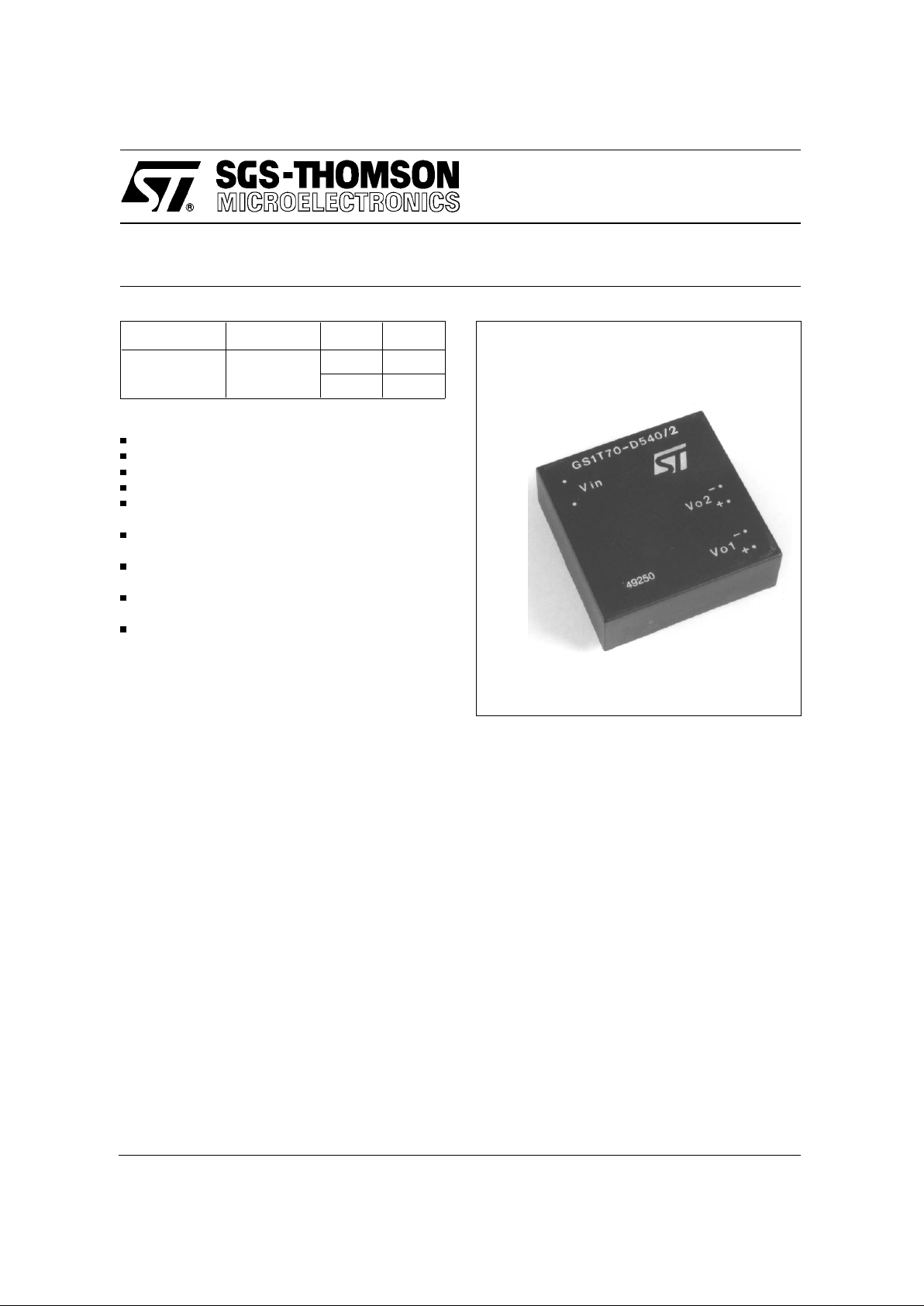
GS1T70-D5 40/2
ISDN DC-DC CONVERTER
20 January 1997 1/5
PRELIMINARY DAT A
Type V
i
V
o
I
o
GS1T70-D540/2 28 to 115 V
out 1 : 5 V 72 mA
out 2 : 40V 12 mA
FEATURES
Wide operating line termination voltage
Positive or negative input voltage polarity
Input and output filtering
Short-circuit protection on both outputs
Input power during shortcircuit within specification
Minimum current drain during stand-by condition:
10µA for Vi<18V
Input-Ou tput2 ins ulation volt age: 3000V
RMS
for
60 seconds
Output1-Output2 insulation voltage: 3000V
RMS
for 60 seconds
Mechani cal di mensi ons (L x W x H): 50.8 mm x
50.8 mm x 18 mm (2" x 2" x 0.71")
DESCRIPTION
The GS1T70-D540/2 converter has been designed
for the “U” interface of an ISDN-NTBA (Network
T ermination Basic Access) system with either 4B3T
or 2B1Q standard trasmission.
Two outputs, 5V/72mA and 40V/12mA are supplied.
The converter offers short-circuit protection (shortcircuit on 40V output doesn’t a ffect 5V outpu t and
the input power never exceeds th e limits of the
specification), input either voltage polarity, 80%
minimum efficiency at maximum load, input and
output filtering to meet very stringent noise requirements.
When the input voltage is below 18V , the converter
offers a very high input impedance and a maximum
quiescent current of 10µA according to the standard
ETR 080.
In addition, the wide operati ng input voltage range
allows it to operate within the whole range of LT
(Line Terminati on) battery voltage and its relevan t
line resistance.
3000V
RMS
isolation voltage for 60 second is provided between input to output 2 and between output
1 and output 2. No insulation is provided between
input and output 1.
The design of the module has been conducted
using, as reference standards, the following:
EN 60950, VDE0878 part 1 class B (EMC),
EN55022 class B (EMC), CCITT 430, ETS 300 012
and ETS 300 047 (ISDN BASIC ACCESS, Safety
and Protection); anyway, please note that no certification proces ses have been carried out on the
module itself.
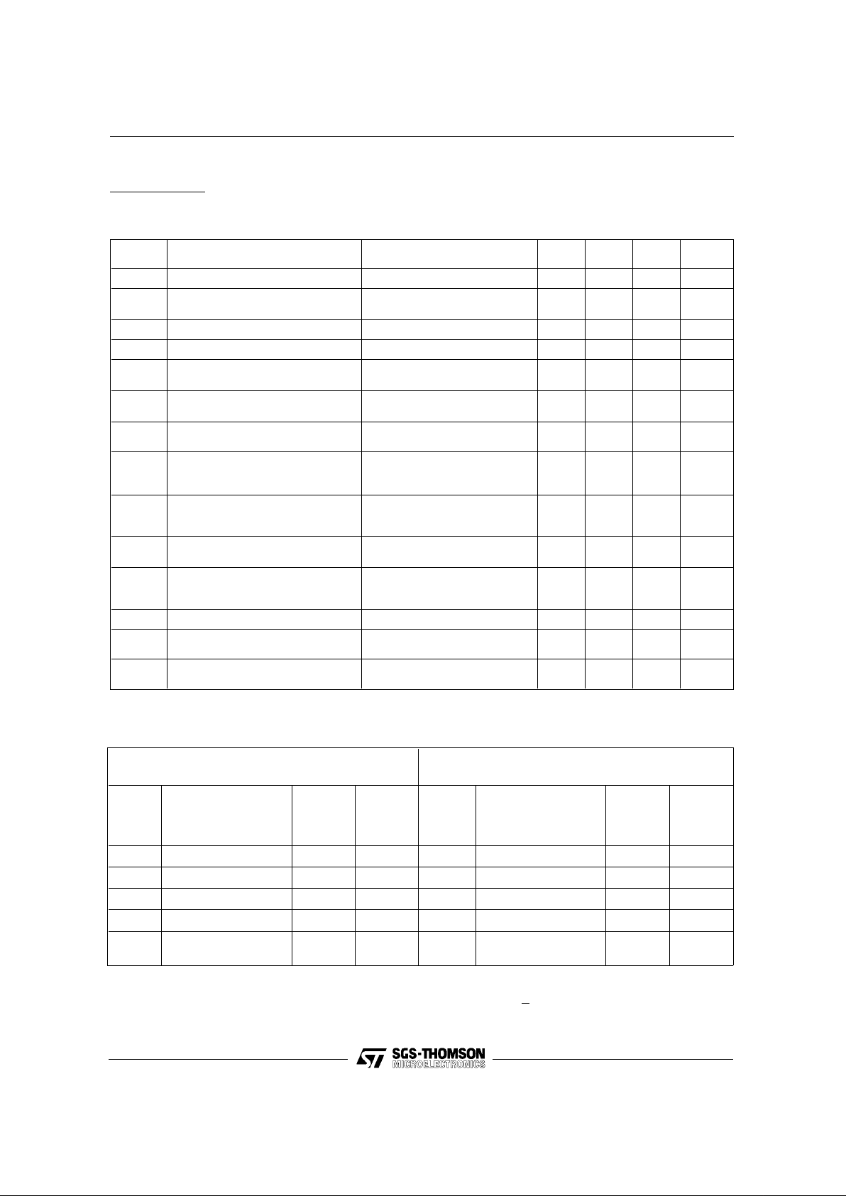
ELECTRICAL CHARACTERISTICS (T
amb
= 25°C unless otherwise specified)
Std. Conditions:
Line Termination voltage: 47 to 71V Line Resistance (Rs): 0 to 600 Ω
87 to 115V 550 to 1400 Ω
Symbol
Parameter Test Co nditions Min Typ Max Unit
V
i
Input Voltage Std. Conditions
28 115 V
V
ist
Start Up Input
Voltage
See fig. 3
28 44 V
V
o1
Output Voltage 1 Std. Conditions
4.75 5 5.25 V
V
o2
Output Voltage 2 Std. Conditions
34 40 42 V
V
or1
Output Ripple
Voltage 1
Std. Conditions
BW = 0 to 20MHz
5 20 mVpp
V
or2
Output Ripple
Voltage 2
Std. Conditions
BW = 0 to 20MHz
10 30 mVpp
I
o1
Output Current 1
Std. Conditions
Po2 = 410 mW Vo1 = 5V
272mA
P
o2
Output Power 2
Std. Conditions
Vo1 = 4.75 to 5.25V
Vo2 = 34 to 42 V
0 420 mW
I
o2max
Max Output Current 2
Std. Conditions
Io1 = 2 to 72 mA
Vo2 = 34 to 40V
12 mA
I
osc2
Output 2 Short
Circuit Current
Std. Conditions
Output Shorted (Indefinite time)
9.8 mA
V
is
Insulation Voltage
Input to Output 2
Output 1 to Output 2 (*)
f = 50 Hz
3000 V
RMS
MTBF
Mean Time Before Failure Ground Fixed
1 Mhours
T
op
Operating Ambient
Temperature Range
-20 +70 °C
T
stg
Storage
Temperature Range
- 40 +85 °C
2/5 20 January 1997
LT (Line Termination Voltage) = 47V to 71V
Rs (Line Resistance) = 0 to 600 Ω
LT (Line Termination Voltage) = 87V to 99V
Rs (Line Resistance) = 550 to 1400 Ω
Max
Input
Power
(mW)
NT Status
Min
Output
Power 1
(5V)[mW]
Min
Output
Power 2
(40V)[mW]
Max
Input
Power
(mW)
NT Status
Min
Output
Power 1
(5V)[mW]
Min
Output
Power 2
(40V)[ mW]
450 Activated 320 0 450 Activated 320 0
950 (*) Activated Emergency 320 410 950 Activated Emergency 320 410
90 Deactivated 40 0 90 Deactivated 40 0
180 Deactivated Emergency 40 45 180 Deactivated Emergency 40 45
1050 (*)
Activated with 40 V
Short circui t
320
Short
circuit
1050
Activated with 40V
Short circuit
320
Short
circuit
N.B.: with the following output loads:
Po1 (5V) : 15 mW and Po2 (40 V) : 410 mW , maintained for a time t > 2s, Vo2 = 34 to 42 V
(*) Note: the values indicated are subordinated to the available input power
OUTPUT POWER CHARACTERISTICS
(*) no insulation is provided between input and output 1
GS1T70-D540/2
 Loading...