

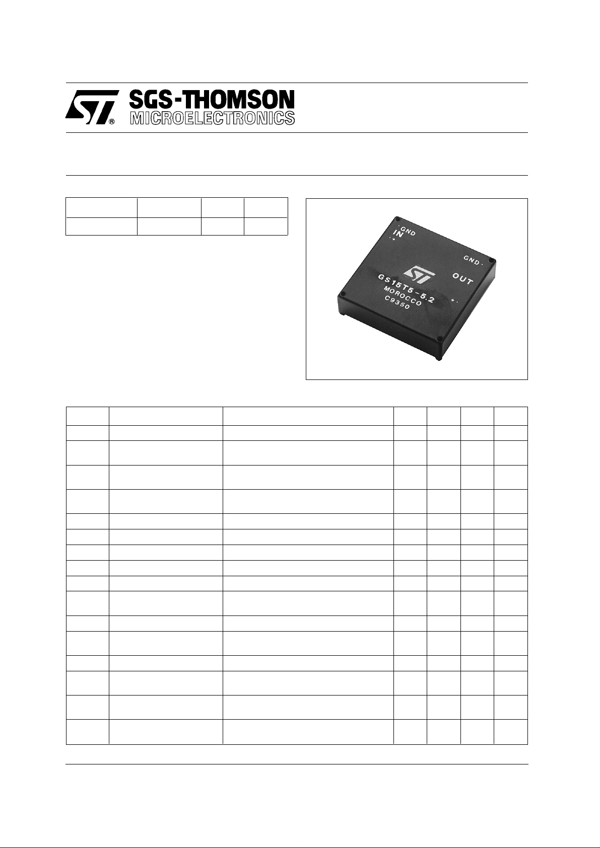
GS15T5-5.2
15 W DC-DC CONVER TER FOR ECL
Type V
GS15T5-5.2 5 V 5,2 V 3 A
in
V
out
I
out
DESCRIPTION
The GS15T5-5.2 is a 15 W DC-DC converter designed to provide a 5.2V isolated output from a 5V
input.
The device can operate with an output current in
the range of 0.0 to 3.0A without any intermittent
operation (packet swit chi ng) .
It offers short-circuit protection and input-output
isolation of 750V
minimum. The integral heatsi nk
DC
allows a large power handling capability and it
provides also an effective shielding to minimize
EMI.
ELECTRICAL CHARACTERISTICS (T
Symbol Parameter T est Conditions Min Ty p Max Unit
δV
δV
R
V
V
I
V
T
V
I
I
V
I
osc
f
T
Input Voltage Vo = 5.2V Io = 0.0 to 3.0A 4.75 5.0 5.35 V
i
Input Reflected
ir
Current
Input Quiescent
iq
Current
Output Voltage Vi = 4.75 to 5.25V
o
Output Current Vi = 4.75 to 5.25V 0.0 3.0 A
o
Line Regulation Vi = 4.75 to 5.25V Io = 3.0A 1 10 mV
OL
Load Regulation Vi = 5.0V Io = 0.0 to 3.0A 10 15 mV
OO
Output Ripple Voltage Vi = 5.0V Io = 3.0A 20 30 mVpp
or
Output Ripple Voltage Vi = 5.0V Io = 3.0A 8 mV
or
Output Short-circuit
Current
Isolation Voltage 750 V
is
Switching Frequ ency Vi = 4.75 to 5.25V
s
η Efficiency Vi = 5.0V Io = 3.0A 77 79 %
Thermal Resistance
thc
Case to Ambient
Maximum Case
c
Temperature
Storage Temperat ure
stg
Range
= 25° C unles s otherwise specified)
amb.
Vi = 5.0V Vo = 5.2V Io = 3.0A
Vi = 5.0V Vo = 5.2V Io = 0.0A
Io = 0.0 to 3.0A
Vi = 5.0V
Io = 0.0 to 3.0A
T
= 25°C Vi = 5.0V Io = 3.0A
amb.
5.04 5.2 5.36 V
– 40
40 50 mApp
87 95 mA
4.75 A
100
8
90 °C
+105 °C
RMS
DC
kHz
°C/W
June 1994 1/2
GS15T 5-5.2
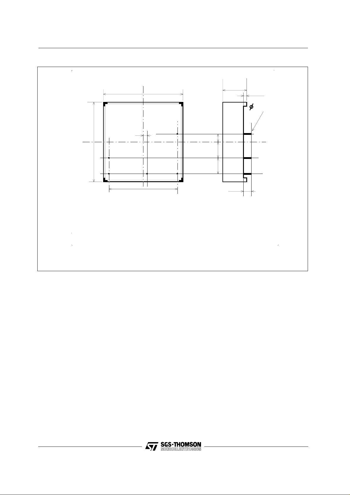
CONNECTION DIAGRAM AND MECHANICAL DATA
50.8 (2.0)
14.7
(0.58)
2 (0.08)
Bottom
View
2.54 (0.1)
50.8
(2.0)
1
234
1 = + Vin
2 = - Vin
3 = Case
4 = - Vout
5 = + Vout
Package G. Dimensions in mm (inches)
43.18 (1.70)
1 (0.04)
5
5.08 (0.20)
10.16 (0.40)
10.16 (0.40)
<5 (0.2)
USER NOTES
Thermal Characteristics
Worst ca se power dissipation at full load i s less than
5W.
T o operate the dev ice at an ambient temperat ure of
60 °C the therm al resi stance case-to- ambient m u st
be lower than 6.5 °C/W.
MTBF Calcul atio ns
The MTBF according to MIL HDBK-217E calculation for a ground benign environment is:
- 216k hours for a case temperature of 91 °C.
- 379k hours for a case temperature of 60 °C.
This last condition can be obtained at T
amb
.= 40 °C
and forced ventilation of 100 feet/ mi nute.
This can be accomplished by adding an external
heatsink or by forced ventilation with air speed of
about 100 linear f eet/minute.
Infor mation fur nis hed is be lie ve d to be ac cu rate an d r elia ble . Ho wev er, SGS- THOM SON Mi cro electro nics a ssu mes no responsibility for the
consequences of use of such infor mation nor for any infring ement of patents or other rights of third parties which may result from its use. No
license is granted by implication or otherwise under any patent or patent rights of SGS-THOMSON Microelectronics. Specification menti oned
in this publication are subje ct to change without notice. This publication supersedes and replaces all information previously supplied.
SGS-THOMSON Microelectronics products are not auth orized f or use a s critic al comp onents in life support devices or systems without express
written approval of SGS-THOMSON Microelectronics.
© 1994 SGS-THOMSON Microelectronics – All Rights Reserved
Australia - Brazil - China - France - Germany - Hong Kong - Italy - Japan - Korea - Malaysia - Malta - Morocco - The Netherlands -
2/2
Singapore - Spain - Sweden - Switzerland - T aiwan - Thailand - United Kingdom - U.S.A.
SGS-THOMSON Microelectronics GROUP OF COMPANIES
 Loading...