

SGS Thomson Microelectronics BZW04-8V5, BZW04-85B, BZW04-85, BZW04-70B, BZW04-70 Datasheet
...
BZW04-5V8/376
FEATURES
PEAK PULSEPOWER: 400W (10/1000µs)
STAND-OFF VOLTAGERANGE:
From5.8V to 376 V
UNI ANDBIDIRECTIONALTYPES
LOW CLAMPINGFACTOR
FASTRESPONSETIME
UL RECOGNIZED
DESCRIPTION
Transildiodes provide high overvoltageprotection
by clamping action. Their instantaneousresponse
to transientovervoltagesmakes them particularly
suited to protect voltage sensitive devices such
as MOS Technology and low voltage supplied
IC’s.
BZW04-5V8B/376B
TRANSIL
F126
TM
ABSOLUTE MAXIMUMRATINGS (T
amb
=25°C)
Symbol Parameter Value Unit
P
PP
P Powerdissipationon infiniteheatsink T
I
FSM
T
stg
T
j
T
L
Peak pulsepower dissipation(see note 1) Tjinitial = Tamb 400 W
=75°C 1.7 W
amb
Non repetitivesurge peakforward current
for unidirectionaltypes
Storagetemperaturerange
Maximumjunction temperature
Maximumlead temperaturefor solderingduring 10s a 5mm
tp= 10ms
Tjinitial = T
30 A
amb
- 65 to+ 175
175
230 °C
fromcase.
Note 1 : Fora surge greater than themaximum values,the diode will fail in short-circuit.
THERMALRESISTANCES
Symbol Parameter Value Unit
R
R
th (j-l)
th (j-a)
Junctionto leads 60 °C/W
Junctionto ambienton printedcircuit. L
lead
=10mm
100 °C/W
°C
°C
January 1998 Ed : 2
1/6

BZW04-xx
ELECTRICALCHARACTERISTICS (T
Symbol Parameter
V
RM
V
BR
V
CL
I
RM
I
PP
α
T
V
F
Unidirectional Bidirectional µAV VmAV A VA10
BZW04-5V8 BZW04-5V8B 1000 5.8 6.45 10 10.5 38.0 13.4 174 5.7 3500
BZW04-6V4 BZW04-6V4B 500 6.4 7.13 10 11.3 35.4 14.5 160 6.1 3100
BZW04-8V5 BZW04-8V5B
BZW04-10 BZW04-10B
BZW04-13 BZW04-13B
BZW04-15 BZW04-15B 1 15.3 17.1 1 25.2 16.0 32.5 71 8.8 975
BZW04-19 BZW04-19B 1 18.8 20.9 1 30.6 13.0 39.3 59 9.2 800
BZW04-20 BZW04-20B 1 20.5 22.8 1 33.2 12.0 42.8 54 9.4 725
BZW04-23 BZW04-23B
BZW04-26 BZW04-26B
BZW04-28 BZW04-28B 1 28.2 31.4 1 45.7 8.8 59.0 39 9.8 510
BZW04-31 BZW04-31B 1 30.8 34.2 1 49.9 8.0 64.3 36 9.6 480
BZW04-33 BZW04-33B 1 33.3 37.1 1 53.9 7.4 69.7 33 10.0 450
BZW04-40 BZW04-40B 1 40.2 44.7 1 64.8 6.2 84 27 10.1 370
BZW04-48 BZW04-48B 1 47.8 53.2 1 77.0 5.2 100 23 10.3 320
BZW04-58 BZW04-58B 1 58.1 64.6 1 92.0 4.3 121 19 10.4 270
BZW04-70 BZW04-70B 1 70.1 77.9 1 113 3.5 146 16.0 10.5 230
BZW04-85 BZW04-85B
BZW04-102 BZW04-102B
BZW04-128 BZW04-128B
BZW04-154 BZW04-154B 1 154 171 1 246 1.6 317 7.0 10.8 125
BZW04-171 BZW04-171B 1 171 190 1 274 1.5 353 6.5 10.8 120
BZW04-188 BZW04-188B
BZW04-213 BZW04-213B
BZW04-256 BZW04-256B
Stand-offvoltage
Breakdownvoltage
Clampingvoltage
Leakagecurrent @ V
RM
Peak pulsecurrent
Voltagetemperaturecoefficient
Forwardvoltagedrop
Types IRM@V
max min max max max typ
=25°C)
amb
VV
CLVBR
V
RM
VBR@IRVCL@I
RM
note2 10/1000µs 8/20µs note3 note4
10 8.5 9.5 1 14.5 27.6 18.6 124 7.3 2000
5 10.2 11.4 1 16.7 24.0 21.7 106 7.8 1550
5 12.8 14.3 1 21.2 19.0 27.2 85 8.4 1200
1 23.1 25.7 1 37.5 10.7 48.3 48 9.6 625
1 25.6 28.5 1 41.5 9.6 53.5 43 9.7 575
1 85.5 95.0 1 137 2.9 178 13.0 10.6 200
1 102 114 1 165 2.4 212 11.0 10.7 170
1 128 143 1 207 2.0 265 9.0 10.8 145
1 188 209 1 328 1.4 388 6.0 10.8 110
1 231 237 1 344 1.5 442 5.2 11.0 100
1 256 285 1 414 1.2 529 4.3 11.0 90
PP
I
I
F
VCL@I
I
I
RM
PP
V
F
V
TC
PP
α
-4
/°CpF
2/6

BZW04-xx
Types IRM@VRMVBR@IRVCL@I
PP
VCL@I
PP
αTC
min max max max typ
note2 10/1000µs 8/20µs note3 note4
Unidirectional Bidirectional µAVVmAVAVA10
BZW04-273 BZW04-273B
BZW04-299 BZW04-299B
1 273 304 1 438 1.2 564 4.0 11.0 85
1 299 332 1 482 0.9 618 3.7 11.0 80
-4
/°CpF
BZW04-342 BZW04-342B 1 342 380 1 548 0.9 706 3.2 11.0 75
BZW04-376 BZW04-376B 1 376 418 1 603 0.8 776 3.0 11.0 70
Fig. 1:
Peakpulse power dissipationversusinitial
junctiontemperature(printed circuitboard).
%I
PP
100
50
10 s
PULSE WAVEFORM 10/1000 s
0
1000 s
Note 2 : Pulse test: tp<50ms.
Note 3 : ∆VBR= αT*(T
Note 4 : VR= 0 V, F = 1 MHz. For bidirectional types,
capacitance value is divided by 2
- 25)*VBR(25°C)
amb
t
3/6
BZW04-xx
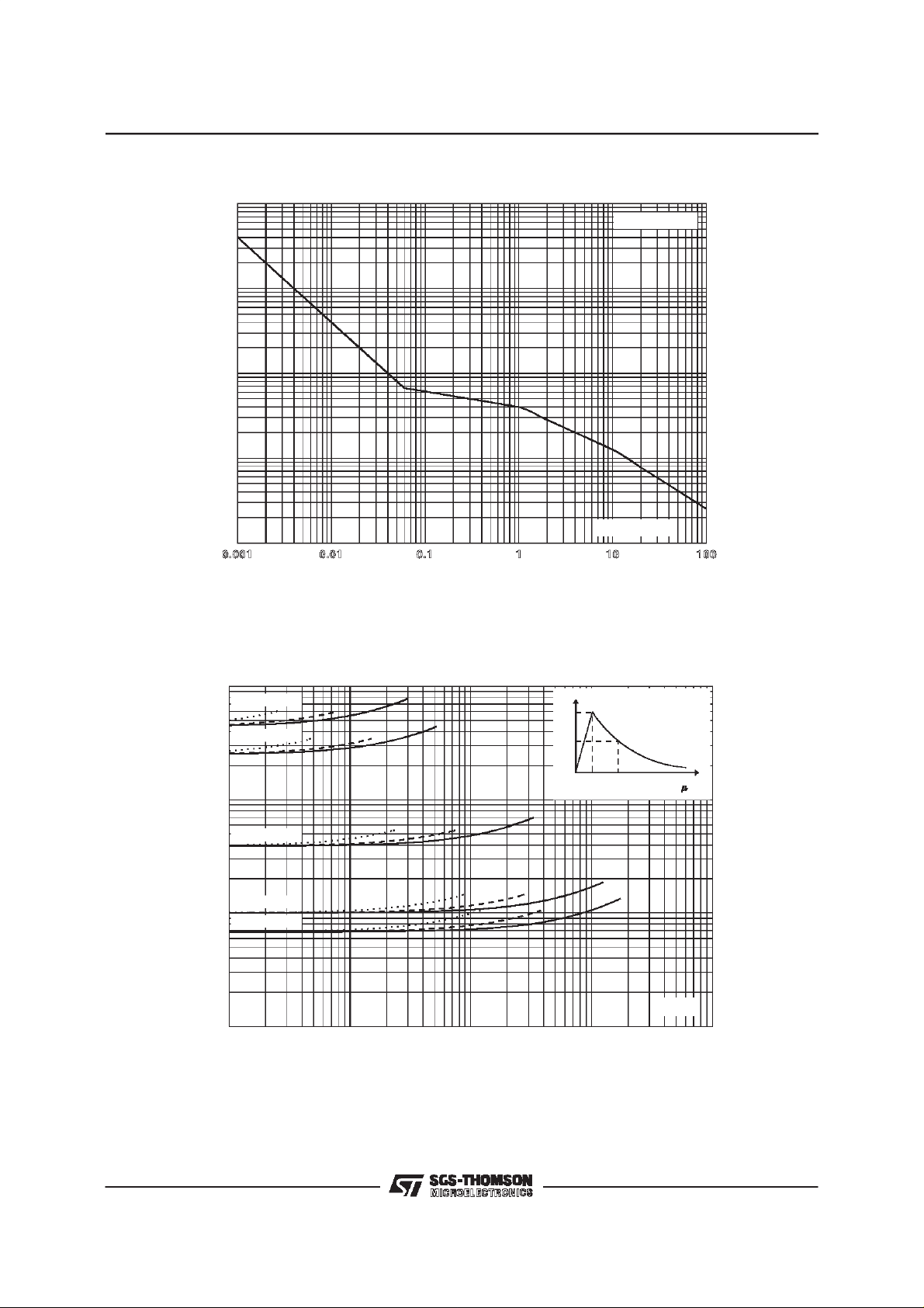
Fig.2 : Peakpulse power versusexponential pulseduration.
P (W)PP
1E5
1E4
1E3
1E2
Tj initial = 25°C
Fig.3 :
1E1
0.001 0.01 0.1 1 10 100
Clampingvoltage versuspeak pulsecurrent.
Exponentialwaveform t
V(V)
CL
1000
100
100
10
10
-
BWZ04 376
BWZ04 213
-
BWZ04 3 3
-
BWZ04 8V5
-
BWZ04 5V8
-
=20µs________
p
= 1 ms-------------
t
p
t
=10 ms...............
p
%Ipp
100
50
0
tp (ms ) EXPO.
Tj initial = 25°C
t
t
r
t<10 s
r
t
Ipp (A)
1
0.1 1 10 100 1000
Note: Thecurves of the figure 3 are specifiedfor a junctiontemperatureof 25 °C before surge.
Thegiven resultsmay be extrapolatedfor other junctiontemperaturesby usingthe followingformula:
∆V
= αT*(T
BR
-25)*VBR(25°C).
amb
Forintermediatevoltages, extrapolatethe givenresults.
4/6

BZW04-xx
Fig. 4a :
Capacitance versus reverse applied
voltage forunidirectional types (typical values).
C(pF)
10000
B
Z
W
0
4
-
5
V
8
B
Z
W
0
4
1000
B
B
B
100
B
10
1
110100
-
1
Z
Z
Z
Z
3
W
0
-
4
2
6
W
0
4
-
5
8
W
0
-
4
1
7
1
W
-
0
4
3
4
2
Tj = 25øC
f=1MHz
V(V)
R
Fig.5 : Peakforwardvoltagedropversuspeakforward
current (typical values for unidirectional types).
Note : Multiplyby 2 for units withVBR> 220V.
Fig. 4b :
Capacitance versus reverse applied
voltage forbidirectional types (typical values).
C (pF)
10000
Tj = 25øC
°
f=1MHz
B
Z
W0
4
-
5
V
8
1000
B
Z
W0
B
Z
W0
B
Z
100
10
Fig.6:
W0
B
Z
W0
B
Z
W0
110100
Transi entthermalimpedanc ejunctionambi-
B
4
-
1
3
B
4
-
2
6
B
4
-
5
8
B
V(V)
4
-
1
7
1
B
4
-
3
4
2
B
R
entversus pulse duration (For FR4 PC Board
100
Zth (j-a) ( C/W)°
lead = 10mm).
with L
Fig.7 : Relative variation of leakagecurrent
versus junction temperature.
10
tp(s)
1
0.01 0.1 1 10 100 1000
5/6

BZW04-xx
ORDERCODE
BZW 04 - 10 B RL
400W
’ ’ = Ammopacktape
’RL’= Tape and reel
PACKAGING:
STAND-OFF VOLTAGE
MARKING : Logo, Date Code, Type Code, Cathode Band(for unidirectionaltypes only).
PACKAGE MECHANICAL DATA
F126 (Plastic)
REF.
BIDIRECTIONAL
Nosuffix : Unidirectional
Millimeters Inches
Min. Typ. Max. Min. Typ. Max.
A 6.05 6.20 6.35 0.238 0.244 0.250
B 26 31 1.024 1.220
∅ C 2.95 3.00 3.05 0.116 0.118 0.120
∅ D 0.76 0.81 0.86 0.030 0.032 0.034
L1 1.27 0.050
DIMENSIONS
Note 1 : The lead is not controlledwithin zone L
Packaging
Weight = 0.40 g.
Information furnished is believed to be accurate and reliable. However, SGS-THOMSON Microelectronics assumes no responsibility for the
consequences of use of such information nor for any infringement of patents or other rights of third parties which may result from its use. No
license is grantedby implication or otherwise under any patentor patentrights ofSGS-THOMSON Microelectronics.Specifications mentioned
in thispublication are subjectto change without notice. This publicationsupersedes and replacesall informationpreviously supplied.
SGS-THOMSONMicroelectronics productsare notauthorizedforuse as critical components in life support devices or systems withoutexpress
written approval of SGS-THOMSON Microelectronics.
6/6
: standardpackagingisintapeand reel.
1998SGS-THOMSON Microelectronics- Printed in Italy - All rightsreserved.
SGS-THOMSON Microelectronics GROUP OF COMPANIES
Australia -Brazil - Canada - China - France - Germany - Italy - Japan - Korea- Malaysia - Malta- Morocco
The Netherlands - Singapore- Spain - Sweden - Switzerland - Taiwan - Thailand - United Kingdom - U.S.A.
1
 Loading...