

SMALLSIGNALSCHOTTKY DIODE
DESCRIPTION
Metaltosilicon junction diodeprimarly intendedfor
UHF mixers and ultrafast switchingapplications.
ABSOLUTE RATINGS (limiting values)
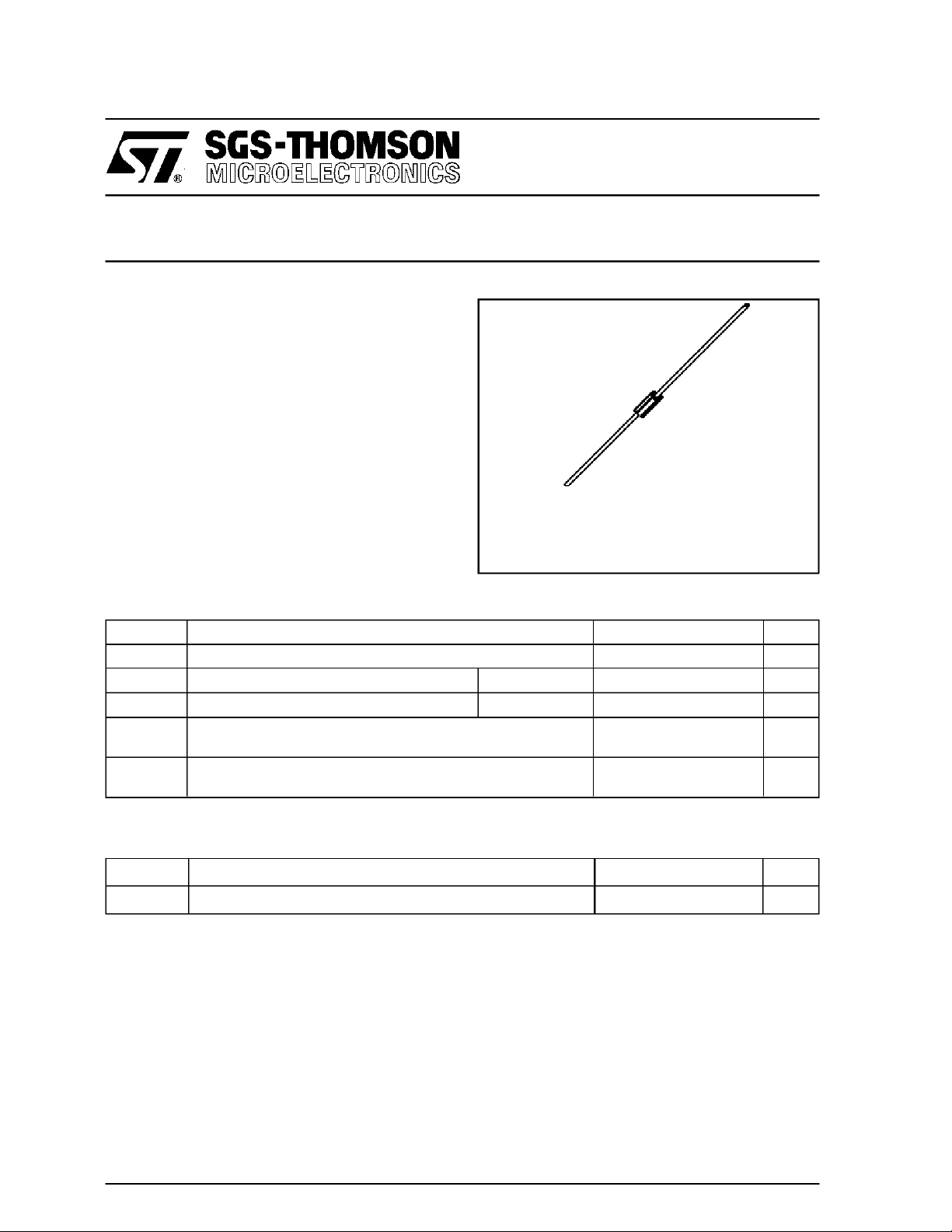
BAT 45
DO 35
(Glass)
Symbol Parameter Value Unit
V
RRM
I
F
I
FSM
T
stg
T
T
L
Repetitive Peak Reverse Voltage 15 V
Forward ContinuousCurrent Ta=25°C30mA
Surge non Repetitive Forward Current tp ≤ 1s 60 mA
Storage andJunction TemperatureRange - 65 to +150
j
Maximum Temperature for Soldering during 10s at 4mmfrom
Case
- 65 to +125
230
THERMAL RESISTANCE
Symbol Test Conditions Value Unit
R
th(j-a)
* On infinite heatsink with 4mm lead length
Junction-ambient* 400 °
°C
°C
°C
C/W
November 1994
1/4
BAT45
ELECTRICAL CHARACTERISTICS
STATIC CHARACTERISTICS
Symbol TestConditions Min. Typ. Max. Unit
V
BR
VF(1)
IR(1)
T
=25°CI
amb
=25°CI
T
amb
=25°CI
T
amb
=25°CI
T
amb
=25°CV
T
amb
R
F
F
F
=10µA
= 1mA
= 10mA
= 30mA
=6V
R
DYNAMICCHARACTERISTICS
Symbol TestConditions Min. Typ. Max. Unit
CT
τ
F (2) T
(1) Pulse test: tp≤ 300µs δ< 2%.
(2) Noise figure test :
- diode isinserted in a tunedstripline circuit
- local oscillator frequency 1GHz
- local oscillator power 1mW
- intermediate frequencyamplifier, tunedon 300MHz, has a noise figure1.5dB
Matched batches available onrequest. Test conditions (forward voltage and/or capacitance) according to customerspecification.
=25°CV
amb
=25°CI
T
amb
=25°C f =1GHz 6 7 dB
amb
= 1V f = 1MHz 1.1 pF
R
= 20mA Krakauer Method
F
15 V
0.38 V
0.5
1
0.1
100 ps
µA
2/4

BAT45
Figure 1. Forward current versus forward
voltage at different temperatures (typical
values).
Figure 2. Forward current versus forward
voltage (typical values).
Figure 3. Reverse current versus junction
temperature.
Figure 4. Reverse current versus continuous
reverse voltage (typical values).
3/4

BAT45
PACKAGE MECHANICAL DATA
DO 35Glass
note 1
DIMENSIONS
REF.
Millimeters Inches
Min. Max. Min. Max.
A 3.050 4.500 0.120 0.117
B 12.7 0.500
∅ C 1.530 2.000 0.060 0.079
∅ D 0.458 0.558 0.018 0.022
E 1.27 0.050
Marking: clear, ring at cathode end.
Weight:0.15g
Cooling method: by convection and conduction
BA B
E
/
O
D
note 2
E
note 1
O/
D
/
O
NOTES
1 - Theleaddiameter ∅ Dis not controlledover zone E
2 - The minimum axial lengh within which the device may be
placedwith its leads bent at right anglesis 0.59”(15 mm)
C
Information furnished is believed to be accurateand reliable.However, SGS-THOMSON Microelectronics assumes no responsability for the
consequences of use of such information nor for any infringementof patents or other rights ofthird parties which mayresultfrom itsuse. No
license is granted by implication or otherwise under any patentor patent rights of SGS-THOMSON Microelectronics. Specificationsmentioned
in this publication are subjectto change without notice. This publication supersedes and replaces all information previously supplied.
SGS-THOMSON Microelectronics products are not authorizedfor useas critical components inlife support devices orsystems without express
written approval of SGS-THOMSON Microelectronics.
1994 SGS-THOMSON Microelectronics - Printed in Italy - All rights reserved.
SGS-THOMSONMicroelectronics GROUP OF COMPANIES
Australia - Brazil - France- Germany - Hong Kong - Italy - Japan- Korea - Malaysia - Malta - Morocco - TheNetherlands
- Singapore- Spain - Sweden - Switzerland - Taiwan- United Kingdom- U.S.A.
4/4
 Loading...