

RF & MICROWAVE TRANSISTORS
SATEL LITE COMMUNICATIO NS APPLI CATION S
.REFRACTORY/GOLD METALLIZATION
.EMITTER SITE BALLASTED
.
:1 VSWR CAPABILITY
∞
. LOW THERMAL RESISTANCE
.INPUT/OUTPUT MATCHING
.METAL/CERAMIC HERMETIC PACKAGE
.P
OUT
DESCRIPTION
The AM1517-012 power transistor isdesignedspecifically for Satellite communications applications
in the 1.5 − 1.7 GHz frequency range.
The device is capable of withstanding any mismatch load condition at any phase angle (VSWR
:1) under full rated conditions. The unit is an
∞
overlay, emitter site ballasted, geometry utilizing
a Refractory/Gold metallization system.
The AM1517-012 is supplied in the AMPAC Hermetic/Ceramic package with internal Input/Output
matching structures.
12 W MIN. WITH 8.5 dB GAIN
=
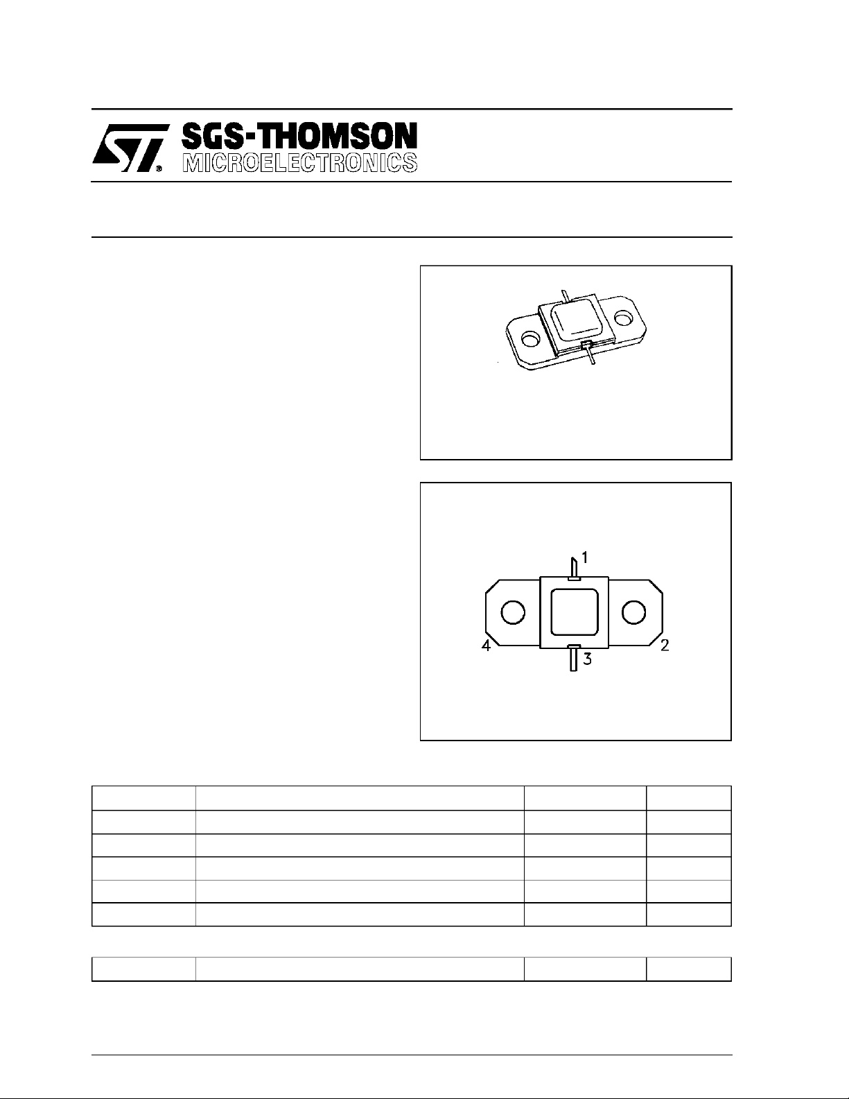
.400 x .400 2NLFL ( S042)
ORDER CODE
AM1517-012
PIN CONNE C TIO N
1. Collector 3. Emitter
2. Base 4. Base
AM1517-012
hermeticallysealed
BRAN DING
1517-12
ABSOLUTE MAXIMUM RATINGS (T
Symbol Parameter Value Unit
P
DISS
I
C
V
CC
T
J
T
STG
THERMA L DAT A
R
TH(j-c)
*Appliesonly to rated RF amplifieroperation
September 1992
Power Dissipation* (TC≤100°C) 27 W
Device Current* 1.25 A
Collector-Supply Voltage* 30 V
Junction Temperature 200
Storage Temperature − 65 to +200
Junction-Case Thermal Resistance* 5.5 °C/W
case
= 25°C)
°
C
°
C
1/6
AM1517-012
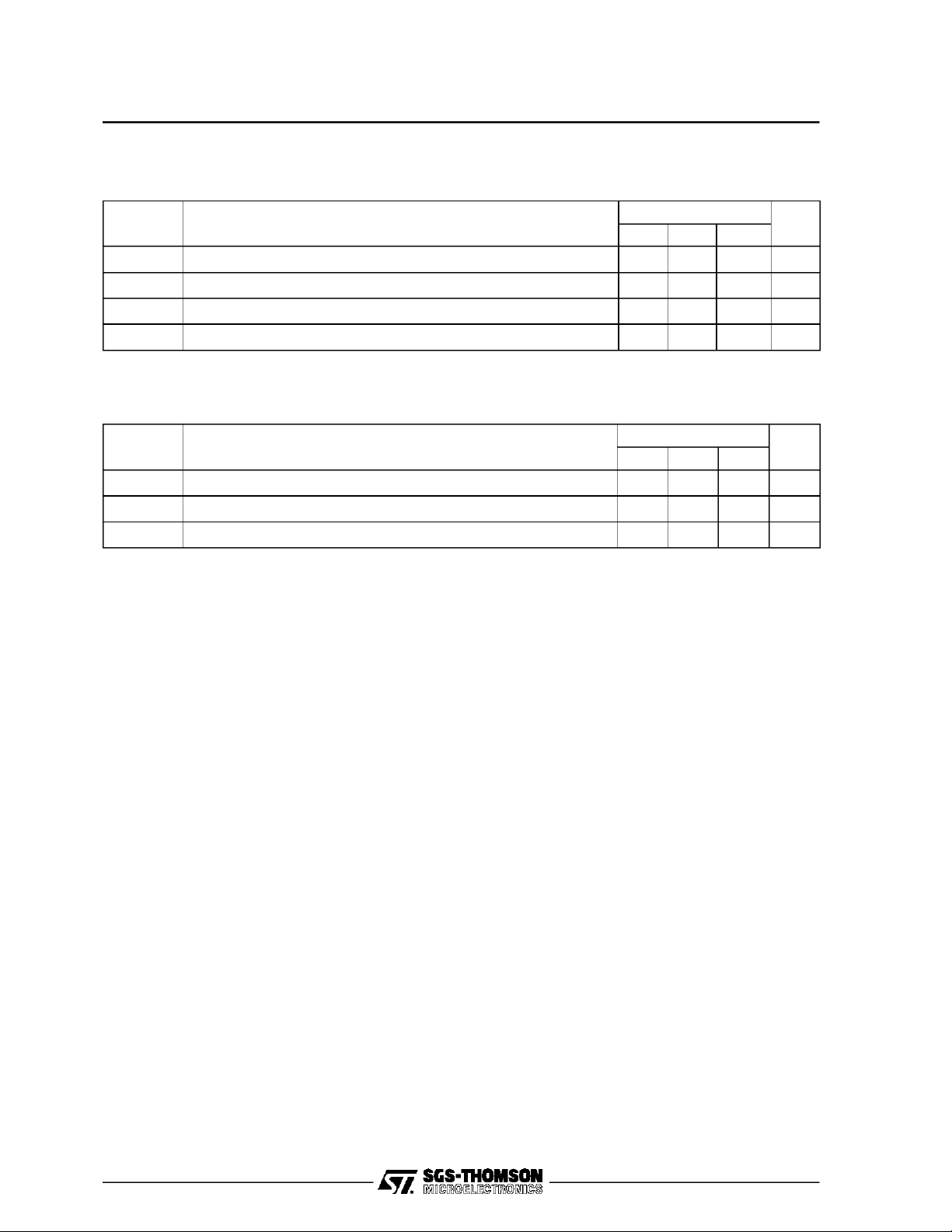
ELEC TRICA L SPEC IFI C A TIONS (Tcase = 25°C)
STATIC
Symbol Test Co ndition s
BV
CBO
BV
EBO
I
CBO
h
FE
DYNAMIC
Symb ol Test Conditi o ns
P
OUT
η
cf=1.5 — 1.7GHz P
G
P
Note: AM1517 series va r y PINto a chieve P
IC= 4mA IE= 0mA 45 — — V
IE= 4mA IC= 0mA 3.0 — — V
VCB= 28V — — 1 mA
VCE= 5V IC= .8A 15 — 150 —
f = 1.5 — 1.7GHz P
f = 1.5 — 1.7GHz P
Alpha-Suf fix added to AM1517 P/N designates band segment.
A -1500=1550 MHz
M - 1620=1660 MHz
S -1625=1675 MHz
1.7W V
IN =
1.7W V
IN =
1.7W V
IN =
; pe rformance guaranteed in 50 MHz i ncrements.
OUT
Value
Min. Typ. Max.
Value
Min. Typ. Max.
28V 12 13 — W
CC =
28V 55 58 — %
CC =
28V 8.5 — — dB
CC =
Unit
Uni t
2/6
 Loading...