

RF & MICROWAVE TRANSISTORS
.REFRACTORY/GOLD METALLIZATION
.EMITTER SITE BALLASTED
.LOW THERMAL RESISTANCE
.INPUT/OUTPUT MATCHING
.OVERLAY GEOMETRY
.METAL/CERAMIC HERMETIC PACKAGE
.P
= 90 W MIN. WITH 13 dB GAIN
OUT
.BANDWIDTH 225 MHz
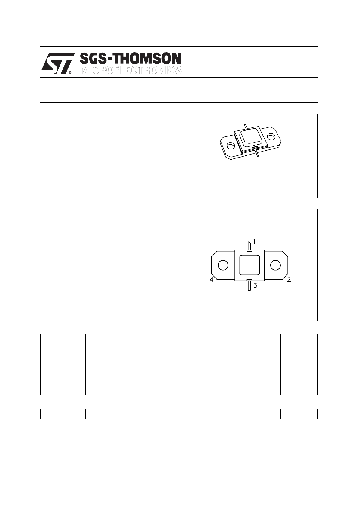
.400 x .400 2NLFL (S042)
ORDER CO DE
AM0912-080
AM0912-080
AVIONICS APPLICATIONS
hermetically sealed
BRANDI NG
0912-80
DESCRIPTION
The AM0912-080 Avionics power transistor is a
broadband, high peak pulse power device specifically designed for avionics applications requiring
broad bandwidth with moderate duty cycle and
pulse width cons trai nts such as grou nd/shi p base d
DME/TACAN.
This device is also designed for specialized applications including JTIDS where reduced power
provided under pulse formats utilizing short pulse
widths and high burst or overall duty cycles.
The AM0912-080 is housed in the unique
AMPAC™ Hermetic Metal/Ceramic package with
internal Input/Output matching structures.
ABSOLUTE MAXIMUM RATINGS (T
Symbol Parameter Value Unit
P
T
DISS
I
V
T
STG
C
CC
J
Power Dissipation* (TC ≤100˚C) 220 W
Device Current* 7.0 A
Collector-Supply Voltage* 50 V
Junction Temperature (Pulsed RF Operation) 250
Storage Temperature
case
= 25°C)
PIN CONNECTION
1. Collector 3. Emitter
2. Base 4. Base
65 to +200
−
°
C
°
C
THERMAL DATA
R
TH(j-c)
*Applies only to rated RF amplifier operation
September 1992
Junction-Case Thermal Resistance* 0.80
°
C/W
1/3
AM0912-080
ELECTRICAL SPECIFICATIONS (T
case
= 25°C)
STATIC
Symbol Test Condi tions
BV
BV
BV
I
CBO
EBO
CER
CBO
h
FE
IC = 40mA IE = 0mA 65 — — V
IE = 10mA IC = 0mA 3.0 — — V
IC = 40mA RBE = 10Ω 65 — — V
VCB = 50V — — 12 mA
VCE = 5V IC = 2A 20 — 120 —
Min. Typ. Max.
Valu e
DYNAMIC
Symbol Test Conditions
P
OUT
η
cf = 960 — 1215MHz PIN = 13W VCC = 50V 38 44 — %
G
P
Note: Pulse Widt h
f = 960 — 1215MHz PIN = 13W VCC = 50V 90 100 — W
f = 960 — 1215MHz PIN = 13W VCC = 50V 8.4 — — dB
10µSec
=
Duty Cycle=10%
Value
Min. Typ. Max.
Unit
Unit
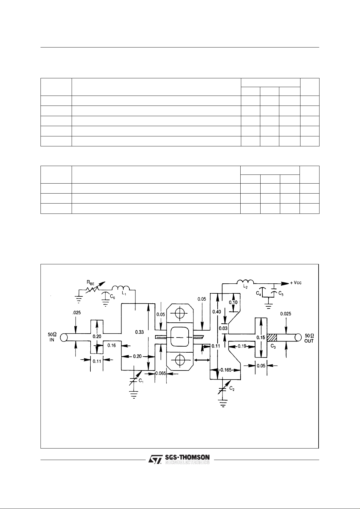
TEST CIRCUIT
Ref. Dwg. No. J-313120
All dimensions are in inches.
Substrate material: .025 thick AI2O
C1,C2: 0.3 - 3.5 pF Johanson Capacitors, or Equiv.
C3 : 100 pF Chip Capacitor
C4,C6: 1500 pF RF Feedthru
3
.120
C5 : 100 MF, Electrolytic 50V
L1,L2 : No. 32 Wire, 4 Turn .062 I.D.
RBE : 0 - 1.0 Ohm
2/3

PACKAGE MECHANICAL DATA
AM0912-080
Information furnished is believed to be accurate and reliable. However, SGS-THOMSON Microelectronics assumes no responsability for the
consequences of use of such information nor for any infringement of patents or other rights of third parties which may results from its use. No
license is granted by implication or otherwise under any patent or patent rights of SGS-THOMSON Microelectronics. Specifications mentioned
in this publication are subject to change without notice. This publication supersedes and replaces all information previously supplied.
SGS-THOMSON Microelectronics products are not authorized for use as critical components in life support devices or systems without express
written approval of SGS-THOMSON Microelectonics.
© 1994 SGS-THOMSON Microelectronics - All Rights Reserved
Australia - Brazil - France - Germany - Hong Kong - Italy - Japan - Korea - Malaysia - Malta - Morocco - The Netherlands -
Singapore - Spain - Sweden - Switzerland - Taiwan - Thailand - United Kingdom - U.S.A
SGS-THOMSON Microelectronics GROUP OF COMPANIES
3/3
 Loading...