

SILICON PNP SWITCHING TRANSISTORS
■ SGS-THOMS O N PREF ERRE D SA LES TYP E S
■ PNP TRANS IST OR S
APPLICATIONS:
■ LINEAR AND SWITCHING INDUSTRIAL
EQUIPMENT
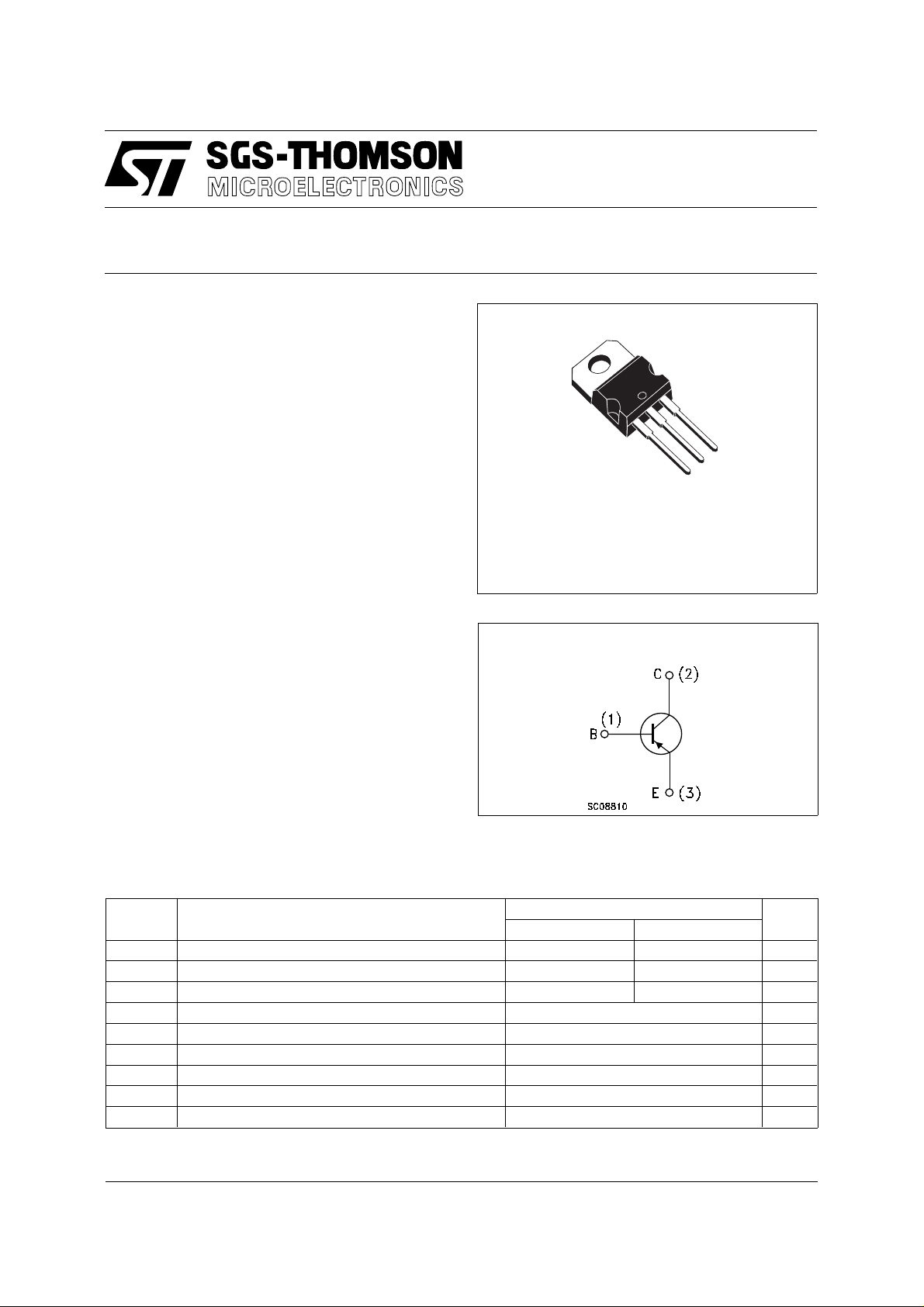
DESCRIPTION
The 2N6107 and 2N6111 are epitaxial-base PNP
silicon transistors in Jedec TO-220 plastic
package. They are intended for a wide variety of
medium power switching and linear applications.
TO-220
2N6107
2N6111
3
2
1
INTERNAL SCHEMATIC DIAGRAM
ABSOL UT E MAXIMU M RATINGS
Symbol Parameter Value Unit
2N6107 2N6111
V
V
V
V
P
T
For PNP devices volt age and current values are negative
Collector-Base Voltage (IE = 0) 80 40 V
CBO
Collector-Emitter Voltage (RBE = 100 Ω)8040V
CEX
Collector-Emitter Voltage (IB = 0) 70 30 V
CEO
Emitter-Base Voltage (IC = 0) 5 V
EBO
Collector Current 7 A
I
C
Base Current 3 A
I
B
Total Dissipation at Tc = 25 oC40W
tot
Storage Temperature -65 to 150
stg
Max. Operating Junction Temperature 150
T
j
o
C
o
C
June 1997
1/4
2N6107/2N6111
THERMAL DATA
R
thj-case
R
thj-amb
Thermal Resistance Junction-case Max 3.12
Thermal Resistance Junction-ambient Max 70
o
C/W
o
C/W
ELECTRICAL CHARACTERISTICS (T
= 25 oC unless otherwise specified)
case
Symbol Parameter Test Conditions Min. Typ. Max. Unit
I
CEX
I
CEO
I
EBO
V
CEO(sus)
V
CER(sus)
V
CE(sat)
V
BE(on)
h
h
FE
Collector Cut-off
Current (V
= - 1.5V)
BE
Collector Cut-off
Current (I
= 0)
B
Emitter Cut-off Current
(I
= 0)
C
∗ Collector-emitter
Sustaining Voltage
for 2N6107 V
for 2N6111 V
T
= 150 oC
C
for 2N6107 V
for 2N6111 V
for 2N6107 V
for 2N6111 V
= 5 V 1 mA
V
EB
IC = 0.1 A
for 2N6107
= 80 V
CE
= 40 V
CE
= 70 V
CE
= 30 V
CE
= 60 V
CE
= 20 V
CE
for 2N6111
∗ Collector-emitter
Sustaining Voltage
IC = 0.1 A RBE = 100 Ω
for 2N6107
for 2N6111
∗ Collector-emitter
Saturation Voltage
IC = 3 A IB = 0.3 A for 2N6107
I
= 2 A IB = 0.2 A for 2N6111
C
I
= 7 A IB = 3.0 A
C
∗ Base-emitter Voltage IC = 3 A VCE = 4 V for 2N6107
I
= 2 A VCE = 4 V for 2N6111
C
I
= 7 A VCE = 4 V
C
∗ DC Current Gain IC = 3 A VCE = 4 V for 2N6107
I
= 2 A VCE = 4 V for 2N6111
C
I
= 7 A VCE = 4 V
C
Small Signal Current
fe
IC = 0.5 A VCE = 4 V f = 50 KHz 20
70
30
80
40
30
30
2.3
0.1
0.1
2
2
1
1
1
1
3.5
1.5
1.5
3
150
150
Gain
f
C
Transition-Frequency IC = 0.5 A VCE = 4 V 4 MHz
T
cbo
Collector-base
VCB = 10 V f = 1 MHz 250 pF
Capacitance
∗ Pulsed: Pulse duration = 300 µs, duty cycle 1.5 %.
For PNP types voltage and current values are negative.
For characteristic curves see the bd534 (PNP) series.
mA
mA
mA
mA
mA
mA
V
V
V
V
V
V
V
V
V
V
2/4
 Loading...