

■ SGS-THOMS O N PREF ERRE D SA LES TYP E S
■ COMPLEMEN TA RY PNP - NPN DEVI CES
■ HIGH CURRENT CAPABILITY
APPLICATIONS
■ GENER AL PURPOSE SWITCHING AND
AMPLIFIER
■ LINEAR AND SWITCHING INDUSTRIAL
EQUIPMENT
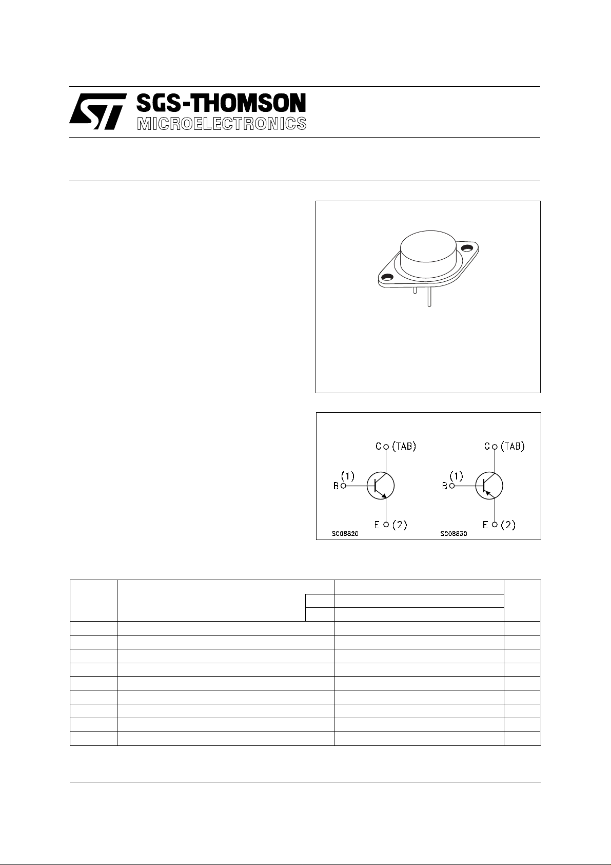
DESCRIPTION
The 2N5884 and 2N5886 are complementary
silicon power transistor in Jedec TO-3 metal case
inteded for use in power linear amplifiers and
switching applications.
2N5884
2N5886
COMPLE MENTARY SILICON
HIGH POWER TRANSISTORS
1
2
TO-3
INTERNAL SCHEMATIC DIAGRAM
ABSOL UT E MAXIMU M RATINGS
Symbol Parameter Value Unit
PNP 2N5884
NPN 2N5886
V
V
V
I
P
T
For PNP types voltage and current values are negative.
Collector-Base Voltage (IE = 0) 80 V
CBO
Collector-Emitter Voltage (IB = 0) 80 V
CEO
Emitter-Base Voltage (IC = 0) 5 V
EBO
Collector Current 25 A
I
C
Collector Peak Current 50 A
CM
Base Current 7.5 A
I
B
Total Dissipation at Tc ≤ 25 oC 200 W
tot
Storage Temperature -65 to 200
stg
Max. Operating Junction Temperature 200
T
j
o
C
o
C
June 1997
1/4
2N5884 / 2N5886
THERMAL DATA
R
thj-case
Thermal Resistance Junction-case Max 0.875
o
C/W
ELECTRICAL CHARACTERISTICS (T
= 25 oC unless otherwise specified)
case
Symbol Parameter Test Conditions Min. Typ. Max. Unit
I
CEV
I
CBO
I
CEO
I
EBO
V
CEO(sus)
Collector Cut-off
Current (V
= -1.5V)
BE
Collector Cut-off
Current (I
= 0)
E
Collector Cut-off
Current (I
= 0)
B
Emitter Cut-off Current
(I
= 0)
C
∗ Collector-Emitter
= rated V
V
CE
VCE = rated V
= rated V
V
CE
= 40 V 2 mA
V
CE
= 5 V 1 mA
V
EB
CEO
Tc = 150 oC
CEO
CBO
1
10
1mA
IC = 200 mA 80 V
Sustaining Voltage
V
V
∗ Collector-Emitter
CE(sat)
Saturation Voltage
∗ Base-Emitter
BE(sat)
IC = 15 A IB = 1.5 A
I
= 25 A IB = 6.25 A
C
1
4
IC = 25 A IB = 6.25 A 2.5 V
Saturation Voltage
V
∗ Base-Emitter Voltage IC = 10 A VCE = 4 V 1.5 V
BE
h
∗ DC Current Gain IC = 3 A VCE = 4 V
FE
h
Small Signal Current
fe
I
= 10 A VCE = 4 V
C
I
= 25 A VCE = 4 V
C
IC = 3 A VCE = 4 V f = 1KHz 20
35
20
100
4
Gain
f
C
CBO
t
∗ Pulsed: Pulse duration = 300 µs, duty cycle 1.5 %
Transition frequency IC = 1 A VCE = 10 V f =1 MHz 4 MHz
T
Collector Base
Capacitance
IE = 0 VCB = 10 V f = 1MHz
for NPN type
for PNP type
t
Rise Time IC = 10 A VCC = 30 V
r
Storage Time 1 µs
s
t
Fall Time 0.8 µs
f
I
= -IB2 = 1A
B1
500
1000pFpF
0.7 µs
mA
mA
V
V
2/4
 Loading...