

®
SMALL SIGNAL SCHO TTKY DIODE
DESCRIPTION
Metal to silicon junction diode featuring high breakdown, low turn-on voltage and ultrafast switching.
Primarly intended for high level U HF/VHF detection
and pulse application with broad dynamic range.
Matched batches are available on request.
1N 5711
DO 35
(Glass)
ABSOLUTE RATINGS
(limiting values)
Symbol Parameter Value Unit
V
RRM
I
P
T
T
T
F
tot
stg
L
Repetitive Peak Reverse Voltage 70 V
Forward Continuous Current*
Power Dissipation*
= 25
T
a
= 25°C
T
a
C
°
15 mA
430 mW
Storage and Junction Temperature Range - 65 to 200
j
Maximum Lead Temperature for Soldering during 10s at 4mm
- 65 to 200
230
from Case
THERMAL RESISTANCE
Symbol Test Conditions Value Unit
R
th(j-a)
Junction-ambient* 400
ELECTRICAL CHARACT E RISTI CS
STATIC CHARACTERISTICS
Symbol Test Conditions Min. Typ. Max. Unit
V
BR
* *
V
F
I
* *
R
T
= 25°CI
amb
= 25°CI
T
amb
T
= 25°CI
amb
= 25°CV
T
amb
= 10µA
R
= 1mA
F
= 15mA
F
= 50V
R
70 V
0.41 V
1
0.2
C/W
°
µ
C
°
C
°
A
DYNAMIC CHARACTERI STICS
Symbol Test Conditions Min. Typ. Max. Unit
C
τ
* On infinite heatsink with 4mm lead length
** Pulse test: t
Matched batches availabl e on request. Test conditions (forward voltage and/or capacitance) according to customer specific ation.
= 25°CV
T
amb
T
= 25°CI
amb
300µs δ < 2%
≤
p
.
= 0V f = 1MHz
R
= 5mA Krakauer Method
F
August 1999 Ed: 1A
2pF
100 ps
1/3
1N 5711
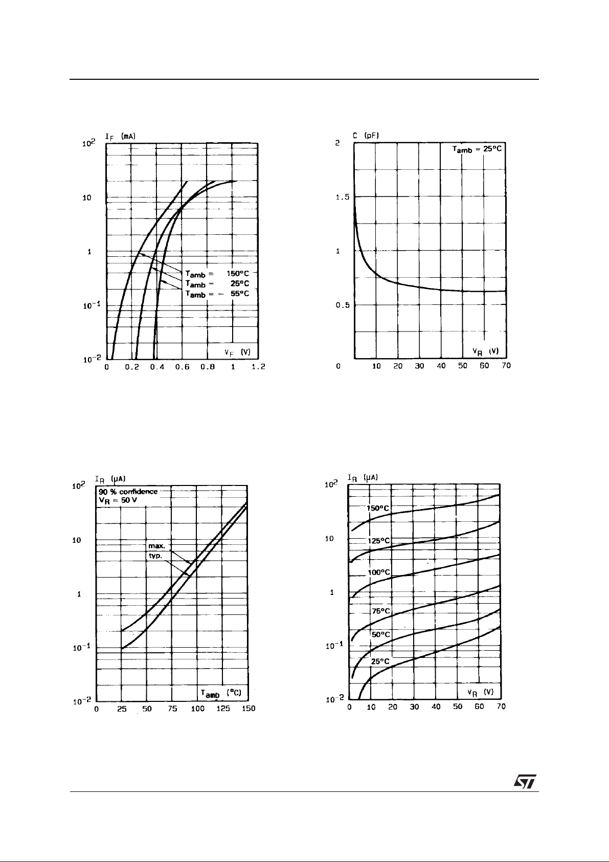
Figure 1. Forward current versus forward
voltage at low level (typical values).
Figure 2. Capacitance C versus reverse
applied voltage V
(typical values).
R
Figure 3. Reverse current versus ambient
temperature.
Figure 4. Rever se current versus continuous
reverse voltage (typical values).
2/3
 Loading...