

Datasheet 1.5KE82A, 1.5KE82CA, 1.5KE7V5CA, 1.5KE7V5A, 1.5KE6V8CA Datasheet (SGS Thomson Microelectronics)
...
1.5K E6V8A/440A
1.5KE6 V8 C A/ 4 4 0CA
TRANSIL
TM
PEAKPULSEPOWER : 1500W (10/1000µs)
BREAKDOWN VOLTAGERANGE:
From6.8V to 440 V
UNIAND BIDIRECTIONALTYPES
LOWCLAMPING FACTOR
FASTRESPONSETIME
UL RECOGNIZED
FEATURES
CB429
Symbol Parameter Value Unit
P
PP
Peakpulse powerdissipation(see note 1) Tj initial= T
amb
1500 W
P Powerdissipationon infiniteheatsink T
amb
=75°C5W
I
FSM
Nonrepetitivesurge peak forwardcurrent
for unidirectionaltypes
tp = 10ms
Tj initial= T
amb
200 A
T
stg
T
j
Storagetemperaturerange
Maximumjunctiontemperature
- 65 to +175
175
°C
°C
T
L
Maximumleadtemperaturefor solderingduring 10s at5mm
fromcase
230 °C
Note 1 : For a surgegreater than the maximum values, the diodewill fail in short-circuit.
ABSOLUTEMAXIMUM RATINGS(T
amb
=25°C)
DESCRIPTION
Transildiodes provide high overvoltageprotection
by clampingaction. Theirinstantaneousresponse
to transient overvoltages makes them particularly
suited to protect voltage sensitive devices such
as MOSTechnologyandlowvoltagesuppliedIC’s.
January 1998 Ed: 2
Symbol Parameter Value Unit
R
th (j-l)
Junctionto leads 20 °C/W
R
th (j-a)
Junctionto ambienton printedcircuit. L
lead
=10mm
75 °C/W
THERMALRESISTANCES
1/6
I
I
F
V
F
VV
CLVBR
V
RM
I
PP
I
RM
V
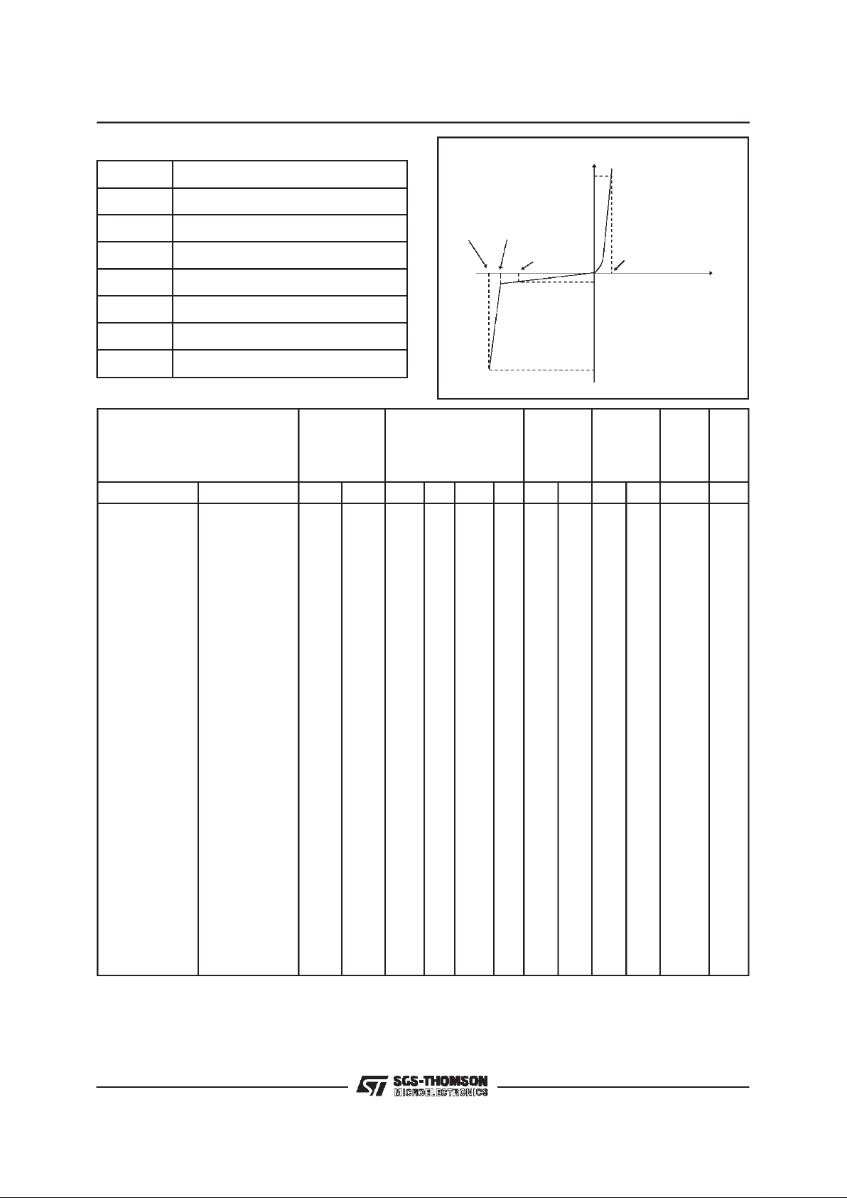
Symbol Parameter
V
RM
Stand-offvoltage
V
BR
Breakdownvoltage
V
CL
Clampingvoltage
I
RM
Leakagecurrent@ VRM
I
PP
Peak pulse current
αT Voltagetemperaturecoefficient
V
F
Forwardvoltagedrop
ELECTRICALCHARACTERISTICS
(T
amb
=25°C)
Types IRM@V
RM
VBR@IRVCL@IPPVCL@I
PP
α
TC
max min nom max max max max typ
note2 10/1000µs 8/20µs note3 note4
Unidirectional Bidirectional
µ
A V V V V mA V A V A 10
-4
/°CpF
1.5KE6V8A 1.5KE6V8CA 1000
5.8 6.45 6.8 7.14 10 10.5 143 13.4 746 5.7 9500
1.5KE7V5A 1.5KE7V5CA 500
6.4 7.13 7.5 7.88 10 11.3 132 14.5 690 6.1 8500
1.5KE10A 1.5KE10CA 10 8.55 9.5 10 10.5 1 14.5 100 18.6 538 7.3 7000
1.5KE12A 1.5KE12CA 5 10.2 11.4 12 12.6 1 16.7 90 21.7 461 7.8 6000
1.5KE15A 1.5KE15CA 1 12.8 14.3 15 15.8 1 21.2 71 27.2 368 8.4 5000
1.5KE18A 1.5KE18CA 1 15.3 17.1 18 18.9 1 25.2 59.5 32.5 308 8.8 4300
1.5KE22A 1.5KE22CA 1 18.8 20.9 22 23.1 1 30.6 49 39.3 254 9.2 3700
1.5KE24A 1.5KE24CA 1 20.5 22.8 24 25.2 1 33.2 45 42.8 234 9.4 3500
1.5KE27A 1.5KE27CA 1
23.1 25.7 27 28.4 1 37.5 40 48.3 207 9.6 3200
1.5KE30A 1.5KE30CA 1
25.6 28.5 30 31.5 1 41.5 36 53.5 187 9.7 2900
1.5KE33A 1.5KE33CA 1
28.2 31.4 33 34.7 1 45.7 33 59.0 169 9.8 2700
1.5KE36A 1.5KE36CA 1 30.8 34.2 36 37.8 1 49.9 30 64.3 156 9.9 2500
1.5KE39A 1.5KE39CA 1 33.3 37.1 39 41.0 1 53.9 28 69.7 143 10.0 2400
1.5KE47A 1.5KE47CA 1 40.2 44.7 47 49.4 1 64.8 23.2 84 119 10.1 2050
1.5KE56A 1.5KE56CA 1
47.8 53.2 56 58.8 1 77 19.5 100 100 10.3 1800
1.5KE62A 1.5KE62CA 1
53.0 58.9 62 65.1 1 85 17.7 111 90 10.4 1700
1.5KE68A 1.5KE68CA 1
58.1 64.6 68 71.4 1 92 16.3 121 83 10.4 1550
1.5KE82A 1.5KE82CA 1 70.1 77.9 82 86.1 1 113 13.3 146 69 10.5 1350
1.5KE100A 1.5KE100CA 1 85.5 95.0 100 105 1 137 11 178 56 10.6 1150
1.5KE120A 1.5KE120CA 1 102 114 120 126 1 165 9.1 212 47 10.7 1000
1.5KE150A 1.5KE150CA 1 128 143 150 158 1 207 7.2 265 38 10.8 850
1.5KE180A 1.5KE180CA 1 154 171 180 189 1 246 6.1 317 31.5 10.8 725
1.5KExx
2/6

Types IRM@V
RM
VBR@IRVCL@IPPVCL@I
PP
αTC
max min nom max max max max typ
note2 10/1000µs 8/20µs note3 note4
Unidirectional Bidirectional
µ
A V V V V mA V A V A 10
-4
/°CpF
1.5KE200A 1.5KE200CA 1
171 190 200 210 1 274 5.5 353 28 10.8 675
1.5KE220A 1.5KE220CA 1 188 209 220 231 1 328 4.6 388 26 10.8 625
1.5KE250A 1.5KE250CA 1 213 237 250 263 1 344 5.0 442 23 11 560
1.5KE300A 1.5KE300CA 1 256 285 300 315 1 414 5.0 529 19 11 500
1.5KE350A 1.5KE350CA 1
299 332 350 368 1 482 4.0 618 16 11 430
1.5KE400A 1.5KE400CA 1
342 380 400 420 1 548 4.0 706 14 11 390
1.5KE440A 1.5KE440CA 1
376 418 440 462 1 603 3.5 776 13 11 360
Note 2 : Pulsetest: tp<50 ms.
Note 3 :
∆
VBR=αT*(T
amb
- 25)*VBR(25°C).
Note 4 : VR= 0 V, F = 1 MHz. For bidirectionaltypes,
capacitancevalue is dividedby 2.
Fig. 1:
Peakpulse powerdissipationversus
initialjunction temperature (printed circuitboard).
10 s
1000 s
%I
PP
50
0
t
PULSE WAVEFORM 10/10 00 s
100
1.5KExx
3/6

Fig. 2 :
Peakpulse powerversusexponentialpulse duration.
Fig.3 : Clampingvoltageversus peak pulse current.
Exponentialwaveform: t
p
=20µs________
t
p
= 1 ms-------------
t
p
= 10 ms...............
Note: The curvesof the figure3 are specifiedfor a junctiontemperatureof 25 °C beforesurge.
Thegiven results maybe extrapolatedfor other junction temperaturesby usingthe following formula:
∆V
BR
= αT*(T
amb
-25)*VBR(25°C).
Forintermediatevoltages,extrapolatethe given results.
1.5KExx
4/6

Fig. 6 : Transient thermal impedance junctionambient versus pulse duration (For FR4 PC
Board with L
lead
= 10mm).
Fig. 5 : Peak forward voltage drop versus peak
forward current (typical values for unidirectional
types).
Note : Multiplyby 2 for units with VBR> 220 V.
Fig. 4b :
Capacitance versus reverse applied
voltage for bidirectionaltypes (typical values).
Fig. 4a :
Capacitance versus reverse applied
voltage for unidirectional types (typical values).
Fig.7 : Relative variation of leakage current
versus junction temperature.
1.5KExx
5/6

Packaging
: standardpackagingis in tapeand reel.
PACKAGEMECHANICAL DATA
CB429(Plastic)
ORDERCODE
1.5 KE 100 C A RL
PACKAGING:
= Ammopack tape
RL = Tape and reel.
REF.
DIMENSIONS
Millimeters Inches
Min. Typ. Max. Min. Typ. Max.
A 9.45 9.50 9.80 0.372 0.374 0.386
B 26 1.024
∅ C 4.90 5.00 5.10 0.193 0.197 0.201
∅ D 0.94 1.00 1.06 0.037 0.039 0.042
L1 1.27 0.050
Note1 : Theleadis notcontrolledwithinzoneL
1
Weight= 0.85 g.
1500 W
BREAKDOWNVOLTAGE
BIDIRECTIONAL
No suffix : Unidirectional
MARKING: Logo, Date Code,Type Code,CathodeBand (for unidirectionaltypesonly).
Information furnished is believed to be accurate and reliable. However, SGS-THOMSON Microelectronics assumes no responsibility for the
consequences of use of such information nor for any infringement of patents or other rights of third parties which may result from its use. No
license is grantedby implication or otherwise under any patentor patentrights of SGS-THOMSON Microelectronics.Specifications mentioned
in this publication are subjectto change withoutnotice. This publication supersedes and replacesall informationpreviously supplied.
SGS-THOMSONMicroelectronics productsare notauthorizedfor use as critical components in lifesupportdevices or systems withoutexpress
written approval of SGS-THOMSONMicroelectronics.
1998 SGS-THOMSON Microelectronics- Printed in Italy - All rights reserved.
SGS-THOMSON Microelectronics GROUP OF COMPANIES
Australia - Brazil - Canada - China - France - Germany - Italy - Japan - Korea - Malaysia- Malta - Morocco
The Netherlands - Singapore - Spain - Sweden- Switzerland - Taiwan -Thailand - United Kingdom - U.S.A.
1.5KExx
6/6
 Loading...