

现货库存、技术资料、百科信息、热点资讯,精彩尽在鼎好!
COMPLEMENTARY SILICON POWER
TIP131, TIP132,TIP135 AND TIP137 ARE
SGS-THOMSON PREFERRED SALESTYPES
DESCRIPTION
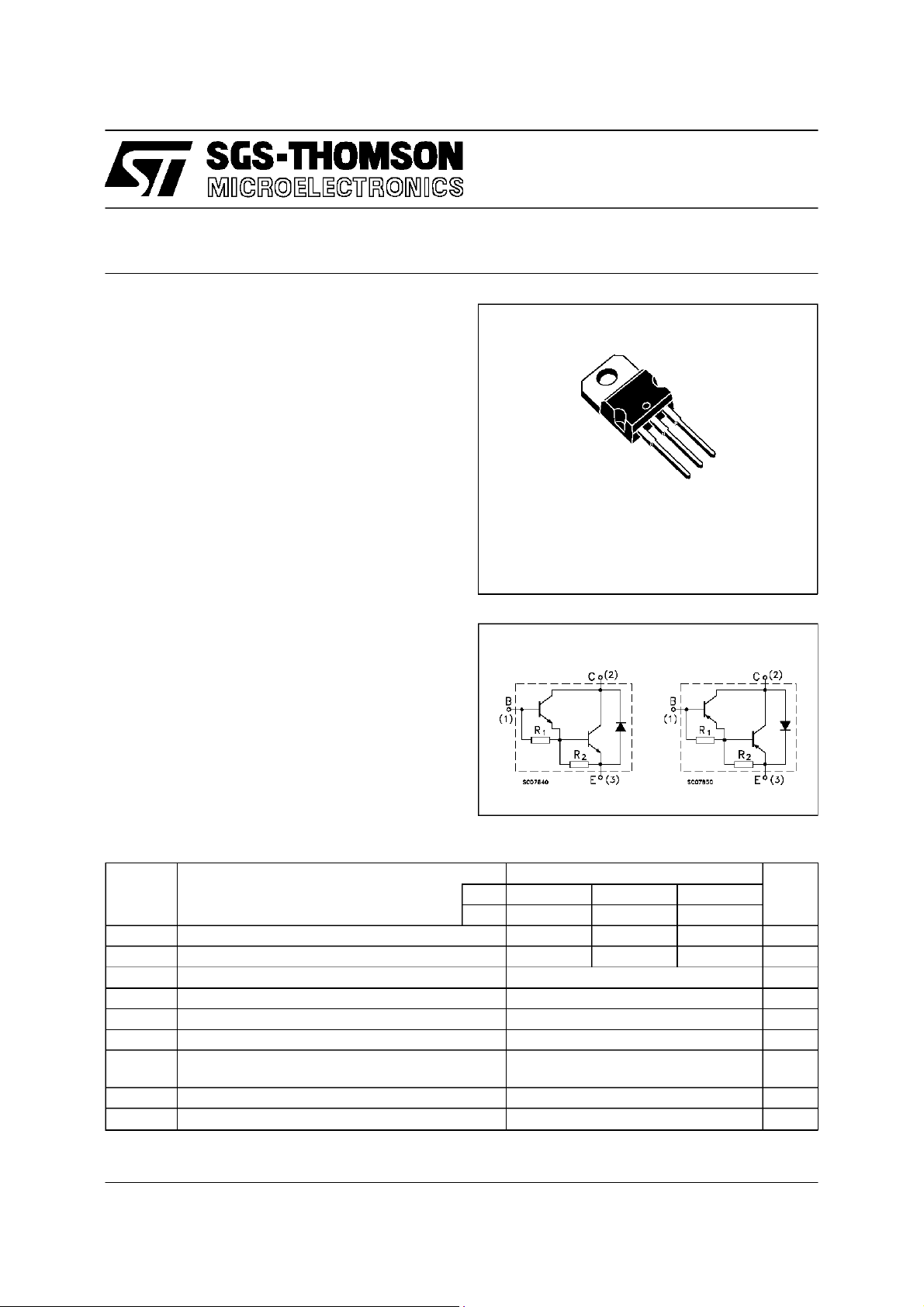
The TIP130, TIP131 and TIP132 are silicon
epitaxial-base NPN power transistors in
monolithic Darlington configuration, mounted in
Jedec TO-220 plastic package. They are intented
for use inpower linearand switching applications.
The complementary PNP types are TIP135,
TIP136and TIP137.
TIP130/131/132
TIP135/136/137
DARLINGTON TRANSISTORS
3
2
1
TO-220
INTERNAL SCHEMATIC DIAGRAM
Typ. = 5 KΩ R2Typ. = 150 Ω
R
1
ABSOLUTE MAXIMUM RATINGS
Symb o l Para met er Val ue Uni t
NPN TI P 130 TIP131 TI P 1 32
PNP TIP135 TIP136 TI P 1 37
V
V
V
I
P
T
* For PNP types voltage and currentvalues are negative.
Collector-B as e Vol ta ge (IE= 0) 60 80 100 V
CBO
Collector-E m it t e r Volt age (IB= 0) 60 80 100 V
CEO
Emitter- Base Volt age (IC=0) 5 V
EBO
Collector Current 8 A
I
C
Collector P e ak Current 12 A
CM
Base Current 0.3 A
I
B
Total Dissipation at T
tot
St orage Tem pera tu r e -65 to 150
stg
Max. Operati ng Junct ion T emper a t ure 150
T
j
T
case
amb
≤ 25 oC
≤ 25 oC
70
2
W
W
o
C
o
C
October 1995
1/4
TIP130/TIP131/TIP132/TIP135/TIP136/TIP137
THERMAL DATA
R
thj-case
R
thj-amb
Therm al Res is t anc e Juncti on-c as e Max
Therm al Res is t anc e Juncti on-am b ient Max
1.78
63.5
o
C/W
o
C/W
ELECTRICAL CHARACTERISTICS (T
=25oC unlessotherwisespecified)
case
Symbol Parameter Test Conditio ns Min. Typ. Max. Unit
I
CEO
I
CBO
I
EBO
V
CEO(sus)
Collect or Cut-off
Current (I
B
=0)
Collect or Cut-off
Current (I
B
=0)
Emitter Cut-off Current
(I
=0)
C
* Collector -Emitter
Sust aining Voltage
=0)
(I
B
V
* Collect or- E m it ter
CE(sat)
Sat urat ion Vo lt age
V
* Base- Em i t t er Volta ge IC=4A VCE= 4 V 2.5 V
BE(on)
h
* DC Cur re nt G ain IC=1A VCE=4V
FE
* For PNP types voltage and current values are negative.
V
= Half Rat es V
CE
V
= Half Rat es V
CB
=5V 5 mA
V
EB
I
=30mA
C
for T I P 130/ 135
for T I P 131/ 136
for TIP132/ 137
CEO
CBO
60
80
100
IC=4A IB=16mA
=6A IB=30mA
I
C
0.5 mA
0.2 mA
2
4
500
=4A VCE=4V
I
C
1000 15000
V
V
V
V
V
2/4

TIP130/TIP131/TIP132/TIP135/TIP136/TIP137
TO-220 MECHANICAL DATA
DIM.
MIN. TYP. MAX. MIN. TYP. MAX.
A 4.40 4.60 0.173 0.181
C 1.23 1.32 0.048 0.051
D 2.40 2.72 0.094 0.107
D1 1.27 0.050
E 0.49 0.70 0.019 0.027
F 0.61 0.88 0.024 0.034
F1 1.14 1.70 0.044 0.067
F2 1.14 1.70 0.044 0.067
G 4.95 5.15 0.194 0.203
G1 2.4 2.7 0.094 0.106
H2 10.0 10.40 0.393 0.409
L2 16.4 0.645
L4 13.0 14.0 0.511 0.551
L5 2.65 2.95 0.104 0.116
L6 15.25 15.75 0.600 0.620
L7 6.2 6.6 0.244 0.260
L9 3.5 3.93 0.137 0.154
DIA. 3.75 3.85 0.147 0.151
mm inch
E
A
L4
D
F2
F1
G1
H2
G
F
C
D1
L2
Dia.
L5
L7
L6
L9
P011C
3/4

TIP130/TIP131/TIP132/TIP135/TIP136/TIP137
4/4
Informationfurnishedis believed to be accurateand reliable. However,SGS-THOMSON Microelectronics assumes no responsability forthe
consequencesof use ofsuch information nor for any infringement of patentsor other rights of third parties which may resultsfrom its use. No
license is grantedby implicationor otherwise underany patentor patent rightsof SGS-THOMSONMicroelectronics. Specifications mentioned
in this publicationare subjectto change withoutnotice.This publication supersedes and replacesall informationpreviously supplied.
SGS-THOMSON Microelectronicsproductsare notauthorizedforuseascritical componentsin lifesupportdevicesorsystems withoutexpress
written approval of SGS-THOMSON Microelectonics.
1995 SGS-THOMSONMicroelectronics - All Rights Reserved
Australia- Brazil - France - Germany- HongKong - Italy- Japan- Korea - Malaysia- Malta- Morocco - TheNetherlands -
Singapore- Spain - Sweden- Switzerland- Taiwan - Thailand - United Kingdom - U.S.A
SGS-THOMSON Microelectronics GROUP OF COMPANIES
.
 Loading...