

Page 1

Installation Manual
Page 2

Contents Page
Introducing the Skyroute UT ................................................................................................................2
1.1 Specifications................................................................................................................................... 2
1.2 Out of the Box ..................................................................................................................................4
Getting Started ................................................................................................................4
2.1 Installation Steps .................................................................................................................................4
2.2 Terminal Descriptions .......................................................................................................................5
Diagram of Positive and Negative Trigger ..............................................................................................6
Diagram of Relay Trigger/Dry Contact Trigger........................................................................................ 6
Diagram of Siren Trigger........................................................................................................................ 7
Secure Installation.......................................................................................................................... 8
Relocating the Antenna.......................................................................................................................... 8
How to Program........................................................................................................... 8
3.1 Installer's Programming ...................................................................................................................8
3.2 Programming Decimal Data............................................................................................................. 9
3.3 Programming Hex Data ...................................................................................................................9
3.4 Programming Toggle Option Sections ............................................................................................10
3.5 Viewing Programming .....................................................................................................................10
Program Descriptions .....................................................................................................................10
4.1 Zone Programming Sections [001] ..................................................................................................10
4.2 Telephone Line Monitor (TLM) .............................................................................................. ..........10
4.3 Swinger Shutdown ..........................................................................................................................10
4.4 Skyroute Programming Sections [803] ............................................................................................11
Activating the Skyroute Transceiver .....................................................................................................12
Calling Connect 24 ...............................................................................................................................12
Skyroute Transceiver Trouble Supervision ............................................................................................12
Skyroute Transceiver Trouble Shooting ............................................................................................12
4.5 PGM Output Options [009] ..............................................................................................................13
PGM Output Attributes ..............................................................................................................14
4.6 Event Buffers ..................................................................................................................................14
4.7 Resetting Factory Defaults ..............................................................................................................14
4.8 Installe's Lockout [Installer's Code] ................................................................................................15
Programming Work Sheets .....................................................................................................................16
Antenna Relocation Diagram ................................................................................................................20
PC16OUT with Skyroute UT Transceiver Diagram ................................................................................21
Skyroute UT with Low V oltage Output from Alarm Panel Diagram .........................................................22
Existing Alarm Control Panel with Skyroute UT (Switched Positive Bell) Diagram ................................23
Existing Alarm Control Panel with Skyroute UT (Switched Negative Bell) Diagram ...............................24
Summary Diagram of the Skyroute UT .................................................................................................25
Appendix A ...........................................................................................................................................26
1
Page 3

Introducing the Skyroute UT
The Skyroute UT offers a new wireless method of communication for the transmission of event information using the
Cellemetry service. Events are transmitted from the Skyroute transceiver via the Cellemetry network to the Clearing
House and then to the Central Station in a fast and reliable manner. Skyroute has been designed for simple and
straightforward installation.
1.1 Specifications
Communication Method
• AMPS Control Channel
Downloading Software Support
• PC580 v2.3 uses DLS-1 v6.7 and up.
Flexible Zone Configuration
• Four fully programmable zones
• 27 zone types; 8 programmable zone attributes
• Normally closed, single EOL
Audible Alarm Output
• 700mA Supervised Bell Output (current limited at 3 amps), 12VDC
• Steady or Pulsed Output
EEPROM Memory
• Does not lose programming or system status on complete AC and Battery failure
Programmable Outputs
• Two programmable outputs; 18 programmable options
• PGM1 = 50mA; PGM2 = 50mA
Powerful 1.5 Amp Regulated Power Supply
• 550 mA Auxiliary Supply, 12 VDC
• Positive Temperature Coefficient (PTC) components replace fuses
• Supervision for loss of AC power, low battery
• Internal clock locked to AC power frequency
Power Requirements
• Transformer = 16.5 VAC, 40VA
• Battery = 12 volt 7 Ah minimum rechargeable sealed lead acid battery
Programmer
• The Skyroute ut can be programmed using any Power keypad
PC5500, PC5508, PC5516, PC5532, PC1555RK and the PC580RK
2
Page 4

System Supervision Features
The system continuously monitors a number of possible trouble conditions including:
• AC power failure
• Low battery condition
• AUX Power Supply Trouble
• Bell output trouble
• Fault by zone
• Tamper by zone
Additional Features
• An event buffer which records the past 128 events with both the time and date at which they occurred;
buffer can be printed using PC5400 serial interface module, or viewed with the LCD5500Z keypad and
DLS-1 software
• Uploading and downloading capability
Antenna
• 3 – 5 dB gain, TNC connector
• Extension Kits available:
- LAE – 3 The 3 Foot Antenna Kit for Skyroute Transceiver
- LAE – 15 The 15 Foot Antenna Kit for Skyroute Transceiver
- LAE – 25 The 25 Foot Antenna Kit for Skyroute Transceiver
RF Power Output
• 3.0 Watts
Power Consumption (Skyroute)
• 12 VDC @30mA, from Panel Keybus
DC, from Bell Circuit
• 12 V
Current in Standby 90mA
Current when Receiving 135mA
Current when Transmitting 1.3A
Dimension
211mm x 234mm x 77mm
3
Page 5

1.2 Out of the Box
Please verify that the following components are included in your system:
• one Skyroute module
• one PC1-OUT module
• one antenna
• one PC5003C main control cabinet
• one PC580 main control circuit board
• one Installation Manual with programming worksheets
• one hardware pack consisting of:
- four plastic circuit board standoffs
- ten 5600Ω (5.6KΩ) resistors
- one 2200Ω (2.2KΩ) resistors
- one 1000Ω (1KΩ) resistors
-
ground connection assembly
- one cabinet door plug
Getting Started
Read this section completely before you begin. Once you have an overall understanding of the installation
process, carefully work through each step.
2.1 Installation Steps
Step 1: Mounting the Unit
Mount the panel in a dry area close to an unswitched AC power source. Before attaching the cabinet to the wall,
be sure to press the four circuit board mounting studs into the cabinet from the back.
NOTE: You must complete all wiring before connecting the battery, or applying AC to the panel.
Step 2: Mounting the Skyroute Transceiver
The Skyroute Transceiver can be mounted in the upper right hand corner of the panel cabinet through
the knock out.The Skyroute Transceiver case attaches to the panel cabinet through the use of clips.
Step 3: Mounting the Antenna
NOTE: The antenna should always be attached to the Skyroute Transceiver for proper operation. The
unit will not function properly if the antenna is not installed.
The antenna attaches to the TNC connector of the Skyroute Transceiver.The antenna should be mounted
as high above ground level as possible while at the same time taking care not to place the antenna
under a Radio frequency shield of any kind. For example do not mount the antenna directly below a
metal roofing over-hang. The Skyroute Transceiver functions best when installed in an unobstructed
“line of sight” to the cellular antenna site.
Step 4: Panel Wiring
Install the 1kΩ resistor (brown, black, red) across the Bell+ and Bell- terminals. Connect all the
zone inputs using the 5.6kΩ resistors (violet, blue, red). Follow connection diagram on page 20
for different configurations.
4
Page 6

Step 5: Skyroute Wiring
• Keybus Connection
The Skyroute transmitter has 4 terminals marked red, black, yellow and green. Connect these four
terminals to the 4 terminals on the main control panel marked KEYBUS (aux+, aux-, yellow and
green).
• Bell IN Terminal
This terminal is used to power the cellemetry modem.This connects to the BELL + on the control
panel. No other wire should be connected to the Bell+ of the control panel or to this terminal.
Step 6: Power up the Control
Once all zone and Keybus wiring is complete, power up the control panel. First, connect the red battery lead to the positive
terminal and the black lead to negative. Then, connect the AC.
NOTE: Connect the battery before connecting the AC. You must apply AC power to the panel for at least 10
seconds, or the panel will not function. The panel will not power up on the battery connection alone.
Step 7: Programming the System
Utilize any Power keypad to program the system. Simply connect the keypad (R , B, Y, G,) terminals to the keybus
(Aux+, Aux-, Yel, Green) on the control panel.
Fill out the Programming Worksheets completely before attempting to program the system.
Step 8: Testing the System
Test the panel thoroughly to ensure that all features and functions are operating as programmed.
2.2 Terminal Descriptions
Battery Connection
A 12V 7Ah rechargeable battery is used as a backup source of power in the event of an AC power failure. The battery
also provides additional current when the panel’s demands exceed the power output of the transformer, such as when
the Skyroute module is transmitting.
NOTE: Do not connect the battery until all other wiring is complete. Connect the battery before connecting the AC.
Connect the RED battery lead to the positive battery terminal; connect the BLACK lead to negative.
AC Terminals – AC
The panel requires a 16.5VAC, 40VA transformer. Connect the transformer to an unswitched AC source and connect the
transformer to these terminals.
NOTE: Do not connect the transformer until all other wiring is complete.
Auxiliary Power Terminals – AUX+ and AUX-
These terminals provide up to 550 mA of additional current at 12 VDC for devices requiring power. Connect the positive
side of any device requiring power to the AUX+ terminal, the negative side to AUX- (ground). The AUX output is protected.
This means that if too much current is drawn from these terminals (such as wiring short), the panel will temporarily shut
off the output until the problem is corrected.
Keybus Terminals – AUX+, AUX-, YEL, GRN
The Keybus is used by the panel to communicate with the Skyroute transceiver, the programming keypad and other
modules. Each module has four Keybus terminals that must be connected to the four Keybus terminals on the panel.
5
Page 7

Programmable Output Terminals – PGM1 and PGM2
Each PGM output is designed so that when activated by the panel, the terminal will switch to ground.
PGM1 can sink up to 50mA of current. Connect the positive side of the LED or buzzer to AUX+, the negative side to PGM1.
PGM2 operates similarly to PGM1. If more than 50 mA of current are required, a relay must be used.
For a list of the programmable output options, please see section the “PGM Output Options” Section.
Zone Input Terminals – Z1 to Z4
Positive Trigger
5.6K
Z COM Z
Relay Trigger or Dry Contact Trigger
Normally Open Contact
-+
Negative Trigger
5.6K
Z COM Z
Normally Closed Contact
-+
-+
CN.O.
5.6K
Z COM Z
-+
CN.C.
5.6K
Z COM Z
6
Page 8
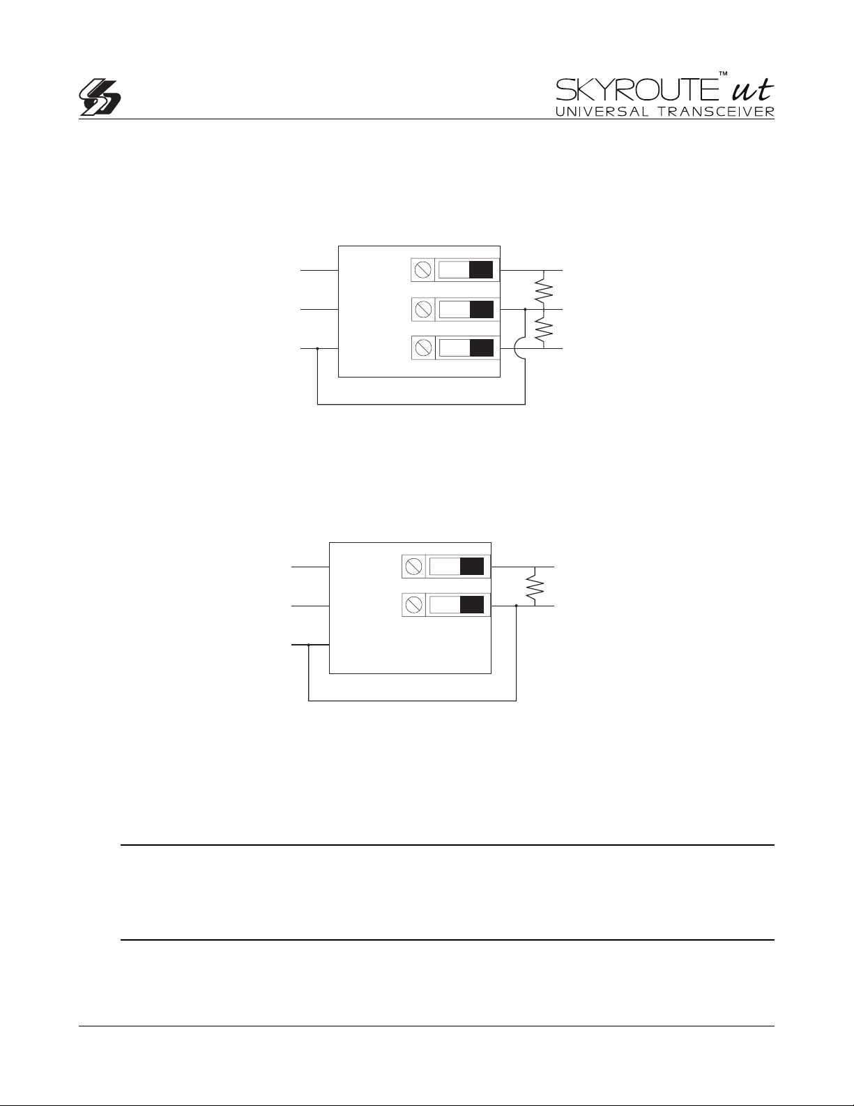
Siren Trigger
Use PC1OUT Module Included
Bell -
+ 12 volt
GND
Bell -
Bell +
(Bell + always active and Bell - switch to ground on alarm)
With this configuration, Zx1 will be trigger on
steady Bell and Zx2 will be trigger on pulsed Bell
(Bell - always to ground and Bell + switch to + on alarm)
Negative Siren Trigger
ORG
RED
BLK
Positive Siren Trigger
ORG
RED
BRG
GND
EMR
BRG
GND
Zx1
COM
Zx2
Zx
COM
GND
BLK
With this configuration, Zx1 will be trigger
every time the Bell is activated
Telephone Connection Terminals – TIP, RING, T-1, R-1
If a telephone line is required for central station communication or downloading, connect an RJ-31X telephone jack in
the following manner:
NOTE: Please ensure that all plugs and jacks meet the dimension, tolerance and metallic plating requirements
of 47 C.F.R. Part 68, SubPart F. For proper operation, no other telephone equipment should be connected
between the control panel and the telephone company facilities. Do not connect the alarm panel communicator
to telephone lines intended for use with a fax machine. These lines may incorporate a voice filter, which
disconnects the line if anything other than fax signals are detected, resulting in incomplete transmissions.
7
Page 9

Secure Installation
For a secure installation, the Skyroute UT must be in a secure, locked, and protected area via
sensors. All entry points must be protected. An instant trip IR sensor would be the most
appropriate for supervision of the panel. A cabinet tamper switch connected to the TMP
terminal of the Skyroute Transceiver is also required.
Relocating the Antenna
If a suitable location is not available for proper Cellemetry coverage, obtain an Antenna Extension
Bracket kit from your DSC/Sur-Gard supplier. Each kit contains an extension cable, a mounting bracket,
instructions, and all required hardware. Three lengths of extension cable are available:
Extension Kit Length of cable
LAE-3 3 feet (0.91 m)
LAE-15 15 feet (4.57 m)
LAE-25 25 feet (7.62 m)
Only use the Extension Kits to extend the mounting range of the antenna. Do not cut or splice
the extension cable. The maximum distance between the Skyroute transceiver and the antenna
is 25 feet (7.62 m) as obtained by using the LAE-25 Extension Kit. Make sure the antenna is
in a physically secured location to avoid tampering.
Secure the TNC connector from the Extension Kit to the mounting bracket, ensuring that the
star washers make solid electrical contact with the mounting bracket.
Remove the antenna from the Skyroute module and connect the extension cable to the TNC
connector on the module. Secure the antenna to the TNC connector mounted on the Extension
Kit Mounting Bracket. Locate the mounting bracket and antenna away from possible sources
of electrical interference. Moving the antenna just a short distance will likely be adequate.
Temporarily secure the mounting bracket in the new location and proceed with testing. If the
test is successful, permanently secure the mounting bracket and antenna at the new location.
How to Program
The following section of the manual describes the Installer’s Programming function and how to program the
various sections.
NOTE: Read the following section of the manual very carefully before you begin programming. We also
recommend filling out the Programming Worksheets section before you program the panel.
3.1 Installer’s Programming
Installer’s Programming is used to program all communicator and panel options. The Installer’s Code is [0580]
by default but should be changed to prevent unauthorized access to programming.
Installer’s Code ........ Section [006]
From an LED Keypad:
1. Enter [*][8][Installer’s Code].
The Program light (or System light on the PC1555RKZ) will flash to indicate that you are in programming
mode. The Armed light will turn on to indicate that the panel is waiting for the three-digit programming section
number.
8
Page 10

2. Enter the three-digit section number corresponding to the section you wish to program.
The Armed light will turn off. The Ready light will turn on to indicate that the panel is waiting for the information required
to complete programming the selected section.
3. Enter the information required to complete section programming (i.e.: numbers, HEX data, or ON/OFF options).
NOTE: If the three-digit section number entered is invalid, or if the module that pertains to the section is not
present, the keypad will sound a two second error tone.
From an LCD Keypad:
1. From any keypad, enter [*][8][Installer’s Code]. The Keypad will display ‘Enter Section’ followed by three dashes.
2. Enter the three-digit number corresponding to the programming section number you wish to program. The keypad
will now display the information required to complete programming the selected section.
3. Enter the information required to complete section programming (i.e.: numbers, HEX data, or ON/OFF options).
If you enter information into a section and make a mistake, press the [#] key to exit the section. Select that section
again and re-enter the information correctly.
NOTE: There must be one digit in each box in the programming section in order for the change to be valid.
3.2 Programming Decimal Data
A set number of programming boxes are allotted for each section requiring decimal data (e.g.: codes, telephone
numbers). If a digit is entered for each program box, the panel will automatically exit from the selected programming
section. The Ready light will turn OFF and the Armed light will turn ON.
On the PC1555RKZ and PC5508Z keypads, you can also press the [#] key to exit a programming section without entering
data for every box. This is handy if you only need to change digits in the first few programming boxes. All other digits
in the programming section will remain unchanged.
3.3 Programming HEX Data
On occasion, hexadecimal (HEX) digits may be required. To program a HEX digit press the [*] key. The panel will enter
HEX programming and Ready light will begin to flash.
The following are the numbers that should be pressed to enter the appropriate HEX digit:
1 = A 2 = B 3 = C 4 = D 5 = E 6 = F
Once the correct HEX digit has been entered, the Ready light will continue to flash. If another HEX digit is required, press
the corresponding number. If a decimal digit is required, press the [*] key again. The Ready light will turn on and the panel
will return to regular decimal programming.
Example:
To enter 402C for your SID number, you would enter:[4][0][2][*][3]:
[4][0][2] to enter digit 4-0-2 (ready light is solid),
[*] to enter Hexadecimal mode (Ready light flashes)
[3] to enter C
NOTE: If Ready light is flashing, any number you enter will be programmed as the HEX equivalent.
9
Page 11

3.4 Programming Toggle Option Sections
Some programming sections contain several toggle options. The panel will use zone lights 1 through 8 to indicate if the
different options are enabled or disabled. Press the number corresponding to the option to turn it ON or OFF. Once all
the toggle options have been selected correctly, press the [#] key to exit the section and save the changes. The Ready
light will turn OFF and the Armed light will turn ON.
Refer to the Programming Worksheets in this manual to determine what each option represents and whether the light
should be ON or OFF for your application.
3.5 Viewing Programming
LED Keypads
Any programming section can be viewed from an LED keypad. When a programming section is entered, the keypad will
immediately display the first digit of information programmed in that section.
The keypad displays the information using a binary format, according to the following chart:
Press any of the Emergency Keys (Fire, Auxiliary or Panic) to advance to the next digit. When all the digits in a section
have been viewed, the panel will exit the section; the Ready Light will turn OFF and the Armed light will turn ON, waiting
for the next three-digit programming section number to be entered. Press the [#] key to exit the section.
LCD Keypad
When a programming section is entered, the keypad will immediately display all the information programmed in that
section. Use the arrow keys (< >) to scroll through the data being displayed. Scroll past the end of the data displayed
or press the [#] key to exit the section.
Program Descriptions
The following section explains the operation of all programmable features and options and provides a summary of all
corresponding programming locations.
4.1 Zone Programming Section [001]
The zone definitions describe how each of the zones you use will operate. Program a two-digit code describing the zone
definition in sections [001]. Enter either 00 if the zone is not used or 11 if the zone is used.
Zone Definitions
[00] Null Zone
The zone is vacant. Unused zones should be programmed as Null zones.
[11] 24hr Zone: If the zone is violated, the unit will report to the Central Station, and will log the event to the buffer. This
zone will follow the programmed number of alarms for swinger shutdown.
4.2 Telephone Line Monitor (TLM)
TLM Enable/Disable Section [015]: Toggle option [7]
4.3 Swinger Shutdown
The swinger shutdown feature is designed to prevent a “runaway” communicator from tying up the central station. After
the panel has communicated the programmed number of transmissions for an event, it will no longer report that event
until the swinger shutdown is reset. Different swinger shutdown levels can be set for zone alarms, zone tampers and
maintenance signals.
By default, each Swinger Shutdown limit is set to [003]. The panel will not send more than three signals for each zone
until the swinger shutdown is reset.
10
Page 12

There will be no communication on zones that have exceeded the limit of alarms set in the Swinger Shutdown counter.
Swinger shutdown will be reset every day at midnight or when the panel is armed. Once reset, the panel will again
communicate normally.
Swinger Shutdown ........ Section [370]
4.4 Skyroute Programming Sections....[803]
All programming on the Skyroute transceiver is done in the installer’s programming mode. Once in programming
mode, enter section [803] to access Skyroute programming.
Zone Definition……………………………………………Sub-Section [01]
This section will determine which "event code" will be sent to the Central Station for each zone.
Configuration Options……………………………………Sub-Section [06]
Channel B enable/disable…………..option[2]
This option must be selected when the Cellemetry provider is a “B” side carrier. Must be on in
Canada.
Home System only enable/disable…..option[3]
This option must be programmed to ensure that the Skyroute transceiver is communicating using the
proper carrier. When selected, the transceiver will only use towers with the same SID. (As programmed in
section [07]).
Skyroute Transceiver SID (System ID)…………………..Sub-Section [07]
The chart below lists the different System ID for each of the territories. For proper activation of the
Skyroute Transceiver the correct SID for the territory that you are in must be entered into section [07] in
Hex.
SID Table
System ID in Memco System ID in Memco
Decimal HEX Decimal HEX
16420 4024 Bell Mobility (Ont.) 16390 4006 MT & T Mobility
16418 4022 TB Tel Mobility 16408 4018 NBTel Mobility
16420 4024 Bell Mobility (Quebec) 16414 401E NewTel Mobility
16458 404A Quebec Tel Mobilité 16430 402E Island TelMobility
16422 4026 BCTEL Mobility 16410 401A SaskTel Mobility
16428 402C MTS Mobility 16384 4000 TELUS Mobility
Skyroute Test Time…………………………………………..Sub-Section [10]
Enter in this section the time of the day (Military Time) that you want the test transmission to be sent.
Test Transmission Day Mask…………………………………………..Sub-Section [11]
Select in this section the day of the week you want the test transmission to be sent.
Skyroute Transceiver Test Rates…………………………………………..Sub-Section [13]
Default Option ON Option OFF
OFF I_____I Option 1 Industrial Disabled
OFF I_____I Option 2 Commercial and Business Disabled
ON I_____I Option 3 Residential and Retail Disabled
OFF I_____I Option 4 Keybus Tests Enabled Keybus Tests Disabled
OFF I_____I Options 5 to 8 For Future Use
11
Page 13

Activating the Skyroute Transceiver
Before activating the Skyroute transceiver, ensure that the control panel is correctly wired and programmed and
operating properly. Make sure that the Skyroute transmitter is properly connected to the keybus and to the bell
positive circuit. When power is applied to the system, the Skyroute will go in initializing mode for few seconds and
then give a visual feedback by indicating signal strength on LED1, LED2 and LED3.
Calling Connect24
O
nce the Skyroute transceiver is indicating the signal strength of the network and that the status indicator (LED5) is
blinking 6 times (not connected to the clearing house) you are ready to call the Voice Response Unit of Connect 24.
Follow the voice prompt and when asked to perform a test, press on SW1 on the Skyroute transceiver to transmit a
test signal. When transmitting, LED4 blink once. If the test is successful, the VRU will give you a confirmation and
LED5 will then blink steady every half-second. Refer to Connect24 information package for more information on the
activation process.
NOTE: The confirmation of a successful test from Connect24 does not guarantee proper transmission of
event activity to your central station.
activation with Connect 24.
You must perform normal test with your monitoring station after
Skyroute Transceiver Trouble Supervision
The Skyroute Transceiver automatically monitors its operation and indicates trouble conditions by flashing LED5 on
the circuit board. LED5 normally flashes once every second when the Skyroute Transceiver is on stand-by (ready to
transmit) mode. Troubles are indicated when LED5 flashes more than once every second. Shown below is the
number of flashes used to indicate each trouble condition in order of importance.
(2) Radio not connected/Radio not responding: Skyroute Transceiver initialization of Cellemetry modem has failed.
(4) Service not available: The Cellemetry modem has failed to register with the cellular network.
(6) Not connected to Clearinghouse: The Skyroute Transceiver has not been activated.
(5) Failure to communicate: A signal has not been successfully communicated to the central station.
(3) Failed self-test: A self-test of the Cellemetry module has failed.
(1) Radio is operating normally: Skyroute Transceiver is ready to transmit.
Skyroute Transceiver Trouble Shooting
If Skyroute Transceiver will not communicate to the clearinghouse, check the following before calling Sur-Gard
technical support.
1.Check all wiring
A. Make sure all the keybus connections are correct.
B. B. Make sure Bell + is connected.
C. Make sure the GND of the Skyroute Transceiver is connected to a zone common or AUX – of the control
panel2. Check the LED5
A. Check number of flashes on LED5. If LED flashes more than once every half a second refer to table 2
B. 6 flashes means not connected to the Clearinghouse. A failed activation attempt. Re-activate.
3. If intermittent failure to communicate is seen (5 flashes), number of attempts (option 23) should be increased to
10 and/or response wait time should be increased to 60 (option 24 = 60).
4. If LED5 flashes once every half a second, yet Skyroute Transceiver does not communicate to clearinghouse call
Sur-Gard Technical support at 1-800-503-5869 ext.1 or 416-665-4494 ext.1.
12
Page 14

4.5 PGM Output Options....[009]
Program the programmable outputs PGM1 and PGM2 on the main board by selecting one of the output options listed
below (exceptions noted).
Main Board PGM OutputsSection [009]
NOTE: PGM outputs cannot be completely disabled in installer’s programming. To disable a PGM output
completely, you must remove all wiring from the output.
[01] Alarm Output
The output will activate when the alarm output is active and will deactivate when the alarm output is silenced. If the alarm
output is pulsing, the PGM output will pulse as well. This output will follow the activation of the alarm output (pre-alert).
[09] System Trouble Output
The PGM output will activate when any of the selected trouble conditions are present. It will deactivate when all the
selected trouble conditions are cleared.
The PGM attributes for this option, programmed in Sections [141] and [142], differ from the standard selection of
attributes.
Program which trouble conditions will activate the output by selecting some or all of the following attributes:
Attribute
[1] Service Required (battery, bell, general trouble, general tamper, general supervisory)
[2] AC Failure
[3] Telephone Line Trouble
[4] Failure to Communicate
[5] Fire Trouble / Zone Fault
[6] Zone Tamper
[7] Zone Low Battery
[8] Loss of Clock
[11] System Tamper (All Sources)
The PGM output will activate when any tamper condition is present and will deactivate when all tampers are restored.
[21]-[24] For future use
13
Page 15

PGM Output Attributes
In addition to programming the output type, you must also program the PGM output attributes for each output.
PGM output options [09] “System Trouble” and [10] “System Event” have their own unique set of attributes listed below
the description of each output type.
PGM output options [01], [03], [05]-[08], [11]-[20] have the following attributes:
Attribute ON OFF
[1] PGM Enable PGM Disable
[3] True Output Inverted Output
AttributeON: the output energizes when activated
Attribute OFF: the output de-energizes when activated
[4] Output Pulsed Output ON/OFF
Attribute ON: the output will activate once for the amount of time programmed in section [164]
when initiated by the user
Attribute OFF: the output will toggle ON or OFF when initiated by the user.
(Only applicable to options [19]-[20].)
PGM attributes return to their default settings when you change PGM output options. Please see the programming
worksheets for a list of the default settings for each PGM output type.
Be careful when selecting the normal and active states of each PGM output to ensure that an undesirable output state
does not occur after a loss and restore of AC power.
NOTE: If you program more than one PGM output as the same output type (e.g. if PGM1 and PGM2 are both
programmed as [19] Command Output 1), the settings for output attributes [1], [2] and [5] must be the same.
This does not apply to outputs programmed as types [09] and [10].
PGM Output AttributesSection [141]-[142]
4.6 Event Buffer
The panel will store the last 128 events which occurred on the system. The Event Buffer will contain the name, time
and date of each event, along with the zone number, access code number or any other information pertaining to the event.
If the Event Buffer Follows Swinger Shutdown option is enabled, the event buffer will not store events after the Swinger
Shutdown level has been reached. This will prevent the panel from overwriting the entire buffer if a problem exists.
The event buffer can be viewed in three different ways: from an LCD keypad printed on-site using the PC5400 printer
module, or it can be uploaded using DLS software.
Event Buffer Follows
Swinger Shutdown .. Section [013]: [7]
4.7 Resetting Factory Defaults
On occasion, it may be necessary to default the main control panel.
To default the main control panel (hardware), perform the following:
1. Remove AC and battery from the panel.
2. Remove all wires from the Zone 1 and PGM1 terminals.
3. With a piece of wire short the Zone 1 terminal to the PGM1 terminal.
14
Page 16

4. Apply AC power to the main panel.
5. When Zone Light 1 is lit on the keypad the default is complete.
6. Remove AC power from the control .
7. Reconnect all original wiring and power up the control.
NOTE: AC power must be used to power the panel. The panel will not default if only the battery is used.
To default the main control panel software and other modules, perform the following:
1. Enter the Installer’s Programming mode.
2. Enter the appropriate programming section [999].
3. Enter the Installer’s Code.
4. Re-enter the appropriate programming section [999].
The panel will take a few seconds to perform the default. When the keypad is again operational the default is complete.
Restore Panel to Default Programming Section [999]
4.8 Installer’s Lockout *[Installer code]
If Installer’s Lockout is selected, a hardware default cannot be performed. If a software default is performed, all
programming will restore to factory default.
If Installer’s Lockout Disable is selected, the panel will restore all programming to factory defaults when a
hardware or software default is performed on the main control panel.
To enable or disable Installer’s Lockout, perform the following:
1. Enter the Installer’s Programming mode.
2. Enter the appropriate programming section: [990] or [991].
3. Enter the Installer’s Code.
4. Re-enter the appropriate programming section: [990] or [991].
Installer Lockout EnableSection [990]
Installer Lockout DisableSection [991]
15
Page 17

Programming Work Sheets
Basic Interface Programming
Zone Definitions
00 Null Zone (Not Used)
11 24 Hour
[001] Zone 1-8 Definitions
Default Default
01 I_______I_______I Zone 1 00 I_______I_______I Zone 5
03 I_______I_______I Zone 2 00 I_______I_______I Zone 6
04 I_______I_______I Zone 3 00 I_______I_______I Zone 7
04 I_______I_______I Zone 4 00 I_______I_______I Zone 8
[006] Installer’s Code
Default
0580 [___][___][___][___]
[009] PGM Output Programming (PGM 1 and 2)
Programmable Output Options
01 Burglary and Fire Bell Output
09 System Trouble Output (with Trouble options)
10 System Event [Strobe (with Event options)]
11 System Tamper (all sources: zones, kpd, modules)
12 TLM and Alarm
13 Kissoff Output
14 Ground Start Pulse
15 Remote Operation (DLS-1 Support)
Default
19
I_______I_______I PGM 1
I_______I_______I PGM 2
10
[015] Third System Option Code
Default Option ON OFF Section
ON
I________I 7 TLM Enabled TLM Disabled
[370] Communication Variables
Default Section
003
I_______I_______I_______I Swinger Shutdown (Alarms and Rest) (001-014 Transmissions, 000=disabled)
003
I_______I_______I_______I Swinger Shutdown (Tampers and Rest) (001-014 Transmissions, 000=disabled)
003
I_______I_______I_______I Swinger Shutdown (Maint and Rest) (001-014 Transmissions, 000=disabled)
I_______I_______I_______I Transmission Delay (001-255 seconds)
000
030
I_______I_______I_______I AC Failure Communication Delay (001-255 minutes)
I_______I_______I_______I TLM Trouble Delay (No. of checks required - valid entries 003 - 255)
003
030
I_______I_______I_______I Test Transmission Cycle (land line) (001-255 minutes/days) (not used)
030
I_______I_______I_______I Test Transmission Cycle (001-255 days) (not used)
I_______I_______I_______I Zone Low Battery Transmission Delay (000-255 days)
007
030
I_______I_______I_______I Delinquency Transmission Cycle (001-255 days / hours)
16
Page 18

Downloading Options
[499] [Installer’s Code] [499] Initiate PC-Link (Local Downloading)
[803] Skyroute Programming
08 Fire
09 Supervisory
11 Burglary
12 Hold-up
13 Gas
14 Heat
15 Medical
16 Panic
17 Emergency
[01] Zone 1-4 Reporting Codes
Default Default
00 I_____I_____I Zone 1 00 I_____I_____I Zone 5 (not used)
00 I_____I_____I Zone 2 00 I_____I_____I Zone 6 (not used)
00 I_____I_____I Zone 3 00 I_____I_____I Zone 7 (not used)
00 I_____I_____I Zone 4 00 I_____I_____I Zone 8 (not used)
[06] Skyroute Configuration Options (1-8)
Default Option ON Option OFF
OFF I_____I Option 1 A Channel Selected A Channel Not Selected
ON I_____I Option 2 B Channel Selected B Channel Not Selected
OFF I_____I Option 3 Home System Only Not in Home System Operation
OFF I_____I Options 4 to 8 For Future Use
[07] Home SID Number
0000 I_____I_____I_____I_____I
This is the SID (in Hex) of the cellular service that is available on the current channel.
[10] Skyroute Test Time
9999 I_____I_____I_____I_____I 0000-2359 (in Military Time)
[11] Test Transmission Day Mask
Default Option ON Option OFF
OFF I_____I Option 1 Test on Sunday Disabled
OFF I_____I Option 2 Test on Monday Disabled
OFF I_____I Option 3 Test on Tuesday Disabled
OFF I_____I Option 4 Test on Wednesday Disabled
OFF I_____I Option 5 Test on Thursday Disabled
OFF I_____I Option 6 Test on Friday Disabled
OFF I_____I Option 7 Test on Saturday Disabled
OFF I_____I Option 8 For Future Use
17
Page 19

[13] Skyroute Test Rates
OFF I_____I Option 1 Industrial Disabled
OFF I_____I Option 2 Commercial and Business Disabled
ON I_____I Option 3 Residential and Retail Disabled
OFF I_____I Option 4 Keybus Tests Enabled Disabled
OFF I_____I Options 5 to 8 For Future Use
[22] Transmission Options
ON I_____I Option 1 Alarms/Restores Disabled
ON I_____I Option 2 Tamper Restoral/Restores Disabled
ON I_____I Option 3 Supervisory/Restores Disabled
ON I_____I Option 4 Low Battery/Restores Disabled
OFF I_____I Option 5 Opening/ Closing Disabled
ON I_____I Option 6 Maintenance Disabled
OFF I_____I Options 7 & 8 For Future Use
[23] Number of attempts
03 I_____I_____I 00 – FF (in HEX)
[24] Response Wait Time
19 I_____I_____I 00 – FF (in HEX) x10 seconds
Sections [30] to [78], if ’00’ is entered, then that reporting code is disabled. If ‘FF’ is in the section, then the
reporting code is enabled. ‘FF’ is the default value.
[30] Alarm Reporting Codes, Zones 1-8
Default Default
FF I_____I_____I Zone 1 Alarm FF I_____I_____I Zone 5 Alarm
FF I_____I_____I Zone 2 Alarm FF I_____I_____I Zone 6 Alarm
FF I_____I_____I Zone 3 Alarm FF I_____I_____I Zone 7 Alarm
FF I_____I_____I Zone 4 Alarm FF I_____I_____I Zone 8 Alarm
[34] Alarm RestoralReporting Codes, Zones 1-8
FF I_____I_____I Zone 1 Alarm Restoral FF I_____I_____I Zone 5 Alarm Restoral
FF I_____I_____I Zone 2 Alarm Restoral FF I_____I_____I Zone 6 Alarm Restoral
FF I_____I_____I Zone 3 Alarm Restoral FF I_____I_____I Zone 7 Alarm Restoral
FF I_____I_____I Zone 4 Alarm Restoral FF I_____I_____I Zone 8 Alarm Restoral
[48] Miscellaneous Tamper Reporting Codes
FF I_____I_____I General System Tamper FF I_____I_____I Keypad Lockout
FF I_____I_____I General System Tamper Rest.
18
Page 20

[75] Maintenance Alarm Reporting Codes
Default Default
FF I_____I_____I Battery Trouble Alarm FF I_____I_____I Aux Power Supply Trouble Alarm
FF I_____I_____I AC Failure Trouble Alarm FF I_____I_____I TLM Trouble Code
FF I_____I_____I Bell Circuit Trouble Alarm FF I_____I_____I General System Trouble
FF I_____I_____I Fire Trouble Alarm FF I_____I_____I General System Supervisory
[76] Maintenance Restoral Reporting Codes
FF I_____I_____I Battery Trouble Restoral FF I_____I_____I Aux Power Supply Trouble Restoral
FF I_____I_____I AC Failure Trouble Restoral FF I_____I_____I TLM Restoral
FF I_____I_____I Bell Circuit Trouble Restoral FF I_____I_____I General System Trouble Restore
FF I_____I_____I Fire Trouble Restoral FF I_____I_____I General System Supervisory
Restore
[77] Miscellaneous Maintenance Restoral Reporting Codes
FF I_____I_____I Phone #1 FTC FF I_____I_____I Event Buffer 75% Full
FF I_____I_____I Phone #2 FTC FF I_____I_____I DLS Lead IN
FF I_____I_____I Phone #1 FTC Restore FF I_____I_____I DLS Lead OUT
FF I_____I_____I Phone #2 FTC Restore FF I_____I_____I Delinquency Reporting Code
[78] Test Transmission Reporting Codes
FF I_____I_____I Periodic Test Transmission FF I_____I_____I Skyroute Test TX Code
FF I_____I_____I System Test
[99] Section [99] is for software defaulting of the Skyroute
10 I_____I_____I
Entering 00 will cause software default of the Skyroute. Entering FF will cause restart of the Skyroute Transceiver.
Entering any other value will not cause default or a restart.
19
Page 21

Skyroute UT Antenna Cable Installation
20
Page 22

PC16-OUT* with a Skyroute UT Transceiver
DSC
CONTROL
PANEL
with PC16-OUT Support
COM
COM COMZ2 Z4 Z6 Z8 RING TIP R-1
GROUND
CONNECTION
Nut
Washer
Cabinet
Bolt
Ground
Rod
RED
BLK
YEL
GRN
T-1
EGNDPGM
BLU
YEL
RED
BLK
SKYROUTE CN
RED BLK
BATTERY
12V 7.0Ah
Typi cal
battery
charge current
is 360 mA.
120Vac
60Hz
PRIMARY
RED
BLK
-
–
SI
Connection for PC-Link
S0
+
AUX
AC
REDBELL
BLK YEL GRN Z1 Z3 Z5 Z7COM
12
PC580
Any Zone
-
+
AC
AUX
RED
12
YEL GRN
Z1 Z3COM
BELL
BLK
YEL
GRN
1K
Z2 Z4
PGM
RING TIP R-1
COM
EGND
T-1
BELL + BELL IN
*PC16-OUT
Any Output
LED 1
LED 2
LED 3
LED 4
SW1
LED 5
Test
Switch
SKYROUTE
YEL
RED
GRN
BLK
Max.
Signal Strength
Min.
Rx/Tx
Status
Indicator
COM
BELL
OUT
Indicator
BELL
IN
TAM
SKYROUTE UT
*Optional device not included with the Skyroute UT
21
Page 23

Skyroute UT Transceiver
(With low voltage output from Alarm Panel)
GENERIC
CONTROL
RED
BLK
-
–
+
BELL
AUX
AC
Programmable Output
Switched to ground
PANEL
RED BLK
BATTERY
12V 7.0Ah
Typi cal
battery
charge current
is 360 mA.
120Vac
60Hz
PRIMARY
S0
SI
Connection for PC-Link
SKYROUTE CN
PC580
YEL GRN
YEL
GRN
12
PGM
5K6
Z1 Z3COM
Z2 Z4
COM
RING TIP R-1
GROUND
CONNECTION
Nut
Washer
Cabinet
Bolt
Ground
EGND
T-1
Rod
RED
BLK
YEL
GRN
Any zone terminal
programmed
as a 24-Hour Zone.
-
+
AC
AUX
BELL
BLK
RED
1K
BELL + BELL IN
SKYROUTE UT
22
Max.
LED 1
Signal Strength
LED 2
Indicator
LED 3
Min.
LED 4
Rx/Tx
Status
SW1
LED 5
Indicator
Test
Switch
SKYROUTE
YEL
RED
BLK
TAM
GRN
COM
BELL
BELL
OUT
IN
Page 24

Existing Alarm Control with a Skyroute UT Transceiver
(Switched Positive Bell)
GENERIC
CONTROL
RED
BLK
-
–
+
BELL
AUX
AC
Parallel with
Siren or Bell
PANEL
RED BLK
BATTERY
12V 7.0Ah
Typi cal
battery
charge current
is 360 mA.
120Vac
60Hz
PRIMARY
50 FT MAX
ORG
RED
BLK
BRG
GND
SKYROUTE CN
S0
SI
20 FT MAX
Connection for PC-Link
PC580
5K6
-
+
AC
AUX
RED
12
YEL GRN
BELL
PGM
Z1 Z3COM
Z2 Z4
RING TIP R-1
BLK
YEL
GRN
1K
COM
EGND
T-1
BELL + BELL IN
RED
BLK
YEL
GRN
GROUND
CONNECTION
Nut
Washer
Cabinet
Bolt
Ground
Rod
SKYROUTE UT
PC1OUT
LED 1
LED 2
LED 3
LED 4
SW1
LED 5
Test
Switch
SKYROUTE
YEL
RED
GRN
BLK
Max.
Signal Strength
Min.
Rx/Tx
Status
Indicator
COM
BELL
OUT
Indicator
BELL
IN
TAM
23
Page 25

Existing Alarm Control with a Skyroute UT Transceiver
(Switched Negative Bell)
GENERIC
CONTROL
RED
BLK
-
–
+
BELL
AUX
AC
PANEL
RED BLK
BATTERY
12V 7.0Ah
Typi cal
battery
charge current
is 360 mA.
120Vac
60Hz
PRIMARY
S0
SI
50 FT MAX
20 FT MAX
Connection for PC-Link
ORG
RED
BLK
BRG
EMR
GND
SKYROUTE CN
PC580
5K6
-
+
AC
AUX
RED
12
YEL GRN
BELL
PGM
Z1 Z3COM
Z2 Z4
RING TIP R-1
BLK
YEL
GRN
1K
COM
EGND
T-1
BELL + BELL IN
RED
BLK
YEL
GRN
GROUND
CONNECTION
Nut
Washer
Cabinet
Bolt
Ground
Rod
SKYROUTE UT
PC1OUT
LED 1
LED 2
LED 3
LED 4
SW1
LED 5
Test
Switch
SKYROUTE
YEL
RED
GRN
BLK
Max.
Signal Strength
Min.
Rx/Tx
Status
Indicator
COM
BELL
OUT
Indicator
BELL
IN
TAM
24
Page 26

Skyroute UT Transceiver
Z COM Z
5.6K
Negative Trigger
Z COM Z
5.6K
Positive Trigger
Relay Trigger or Dry Contact Trigger
Z COM Z
5.6K
-+
CN.O.
-+
Normally Open Contact
Z COM Z
5.6K
-+
CN.C.
-+
Normally Closed Contact
Siren Trigger
Use PC1OUT Module Included
ORG
RED
BLK
Bell -
+ 12 volt
GND
Zx1
COM
Zx2
BRG
GND
EMR
Negative Siren Trigger
(Bell + always active and Bell - switch to ground on alarm)
With this configuration, Zx1 will be trigger on
steady Bell and Zx2 will be trigger on pulsed Bell
Positive Siren Trigger
(Bell - always to ground and Bell + switch to + on alarm)
With this configuration, Zx1 will be trigger
every time the Bell is activated
ORG
RED
BLK
Bell -
Bell +
GND
Zx
COM
BRG
GND
RED BLK
BATTERY
12V 7.0Ah
Typic al
battery
charge current
is 360 mA.
120Vac
60Hz
PRIMARY
SI
Connection for PC-Link
S0
PC580
5K6
-
+
AC
12
YEL GRN
AUX
BLK
RED
Z1 Z3COM
BELL
YEL
1K
BELL + BELL IN
Z2 Z4
PGM
GRN
RING TIP R-1
EGND
COM
T-1
SKYROUTE UT
GROUND
CONNECTION
Washer
Cabinet
Ground
RED
BLK
YEL
GRN
25
SKYROUTE CN
Nut
Bolt
Rod
Max.
LED 1
Signal Strength
LED 2
Indicator
LED 3
Min.
LED 4
Rx/Tx
Status
SW1
LED 5
Indicator
Test
Switch
SKYROUTE
YEL
RED
BLK
TAM
GRN
COM
BELL
BELL
OUT
IN
Page 27

Appendix A
SIA Communications For Skyroute
SIA Communication Format:
The SIA communication format used in this product follows the Level 2 specifications of
the SIA Digital Communication Standard - February 1993. This format will send the
Account Code along with a its data transmission. Below are the Zone Alarms & Alarm
Restores (Zones 01-32) as well as any additional codes that can be transmitted;
Terms:
Code Description
— Not used
zz Zone #
us User #
ln Line
ex Expander #
Alarms:
Event Description SIA Message Zone# Identified
Null Zone (Not used) ———————- ———
Delay 1 BAzz/BHzz Yes
Delay 2 BAzz/BHzz Yes
Instant BAzz/BHzz Yes
Interior BAzz/BHzz Yes
Delay H.A. BAzz/BHzz Yes
Interior H.A. BAzz/BHzz Yes
24 Hr Burglary BAzz/BHzz Yes
Standard Fire FAzz/FHzz Yes
Delayed Fire FAzz/FHzz Yes
24 Hour Supervisory (LINKS) UAzz/UHzz Yes
24 Hr Supervisory Buzzer UAzz/UHzz Yes
24 Hr Supervisory USzz/URzz Yes
24 Hr Medical MAzz/MHzz Yes
24 Hr Panic PAzz/PHzz Yes
24 Hr Hold-up HAzz/HHzz Yes
24 Hr Gas GAzz/GHzz Yes
24 Hr Heat KAzz/KHzz Yes
24 Hr Emergency QAzz/QHzz Yes
24 Hr Sprinkler SAzz/SHzz Yes
24 Hr Water WAzz/WHzz Yes
24 Hr Freeze ZAzz/ZHzz Yes
24 Hr Latching Tamper BAzz/BHzz Yes
Momentary Keyswitch Arm BAzz/BHzz Yes
Maintained Keyswitch Arm BAzz/BHzz Yes
26
Page 28

SIA Communications For Skyroute(continued)
Event Description SIA Message Zone# Identified
Duress Alarm HA00
Opening After Alarm OR00
Keypad [F]ire FAzz/FHzz Yes
Keypad [A]uxiliary MAzz/MHzz Yes
Keypad [P]anic PAzz/PHzz Yes
PGM2:
2 Wire Smoke FA99/FH99
Audible 24 Hour UA99/UH99
Silent 24 Hour UA99/UH99
Zone Tamper (1-32) TAzz Yes
Zone Tamper Restorals (1-32) TRzz Y es
General System Tamper / Restore TA00/TR00
Closing by Access Codes CLus Yes
(1-32,33,34,40,41,42)
Partial Closing CGus Yes (using UBzz)
Opening by Access Codes OPus Yes
(1-32,33,34,40,41,42)
Battery Trouble YT00/YR00
AC Failure Trouble AT00/AR00
Bell Circuit Trouble UT99/UJ99
Fire Trouble FT00/FJ00
Auxiliary Power Supply Trouble YP00/YQ00
TLM Trouble Code (via Skyroute) LT00
General System Supervisory / Restore ET00/ER00
General System Trouble / Restore YX00/YZ00
TLM Restoral LR00
FTC Fail / FTC Restoral YC00/YK00
Event Buffer 75% Full Since Last Upload JL00
Periodic Test Transmission RP00
System Test RX00
Skyroute Test Transmission Code TX00 Signal Strength
Zone Fault Alarm/Restoral UTzz/UJzz
Burglary Verified BV00
Delinquency Code CD00
Zone Low Battery XTzz/XRzz
Recent Closing CR00 User NOT Identified
Zone Expander Supervisory UA00/UH00
Keypad Lockout JA00
Special Closing (DLS, Keys, Maint, Quick) CLus Yes (User)
Special Opening (DLS, Keys, Maint) OPus Yes (User)
DLS Lead In RB00
DLS Lead Out (Successful) RS00
Auto-Arm Cancellation CE00
Late to Close CI00
Skyroute Tamper Cut TAzz/TRzz Yes
Keybus Cut USzz/URzz Yes
Telephone Line Cut LTln/LRln
Expansion Device ETex/ERex
1
2
Yes
Yes
27
Page 29

Page 30

Limited Warranty
Sur-Gard Ltd. warrants that for a period of sixty months from the date of purchase, the product shall be free of defects in materials
and workmanship under normal use and that in fulfillment of any breach of such warranty, Sur-Gard Ltd. shall, at its option,
repair or replace the defective equipment upon return of the equipment to its repair depot. This warranty applies only to defects
in parts and workmanship and not to damage incurred in shipping or handling, or damage due to causes beyond the control
of Sur-Gard Ltd., such as lightning, excessive voltage, mechanical shock, water damage, or damage arising out of abuse,
alteration or improper application of the equipment.
The foregoing warranty shall apply only to the original buyer, and is and shall be in lieu of any and all other warranties, whether
expressed or implied and of all other obligations or liabilities on the part of Sur-Gard Ltd. This warranty contains the entire
warranty. Sur-Gard neither assumes, nor authorizes any other person purporting to act on its behalf to modify or to change
this warranty, nor to assume for it any other warranty or liability concerning this product.
In no event shall Sur-Gard Ltd. be liable for any direct, indirect or consequential damages, loss of anticipated profits, loss of
time or any other losses incurred by the buyer in connection with the purchase, installation or operation or failure of this product.
Warning
Sur-Gard Ltd. recommends that the entire system be completely tested on a regular basis. However, despite frequent testing,
and due to, but not limited to, criminal tampering or electrical disruption, it is possible for this product to fail to perform as
expected.
How to contact us:
Sales
For information about additional products, please call our sales number: 1-800-418-7618, or e-mail us
at sales@sur-gard.com.
Technical Support
If you have questions or problems when using Sur-Gard products, you can call technical support. If you are within
the United States, Puerto Rico, the U.S. Virgin Islands or Canada, you can get support by dialing 1-800503-5869
ext.I. If you are outside these areas, please call (416) 665-4494 ext.1, or e-mail us at support@sur-gard.com.
Internet
Visit our Sur-Gard site. You will be able to search the Sur-Gard technical information database and read information about
new products. You will also be able to send us your questions. Our World Wide Web address is http://www.sur-gard.com.
© Sur-Gard Security Systems Ltd.
401 Magnetic Drive, Unit 24-28,
Downsview, Ontario, M3J-3H9
Phone: 416-665-4494
Sales:1-800-418-7618
Technical Support:1-800-503-5869
www.sur-gard.com
29003347 R0
Printed in Canada
 Loading...