

SG Models SEA276 Assembly Manual
ASSEMBLY MANUAL
“ Graphics and specications may change without notice ”.
Code: SEA276
Specications:
Wingspan---------------56.3 in (143 cm).
Wing area---------------563.6 sq.in ( 36.4q.dm).
Weight-------------------6.6-6.8 lbs ( 3.0-3.1 kg).
Length-------------------45.3 in (115.1 cm).
Engine-------------------10cc
Radio--------------------7 channels with 7 servos.
1
P-51D MUSTANG
INTRODUCTION.
Instruction Manual.
ank you for choosing the P-51D MUSTANG ARF by SG MODELS. e P-51D MUSTANG
was designed with the intermediate/advanced sport yer in mind. It is a semi scale airplane
which is easy to y and quick to assemble. e airframe is conventionally built using balsa,
plywood to make it stronger than the average ARF, yet the design allows the aeroplane to be
kept light. You will nd that most of the work has been done for you already. e motor mount
has been tted and the hinges are pre-installed. Flying the P-51D MUSTANG is simply a joy.
is instruction manual is designed to help you build a great ying aeroplane. Please read this
manual throughly before starting assembly of your P-51D MUSTANG . Use the parts listing
below to indentify all parts.
WARNING.
Please be aware that this aeroplane is not a toy and if assembled or used incorrectly it is
capable of causing injury to people or property. WHEN YOU FLY THIS AEROPLANE YOU
ASSUME ALL RISK & REPONSIBILITY.
If you are inexperienced with basic R/C ight we strongly recommend you contact your R/C
supplier and join your local R/C model Flying Club. R/C Model Flying Clubs oer a variety of
training procedures designed to help the new pilot on his way to successful R/C ight. ey
will also be able to advise on any insurance and safety regulations that may apply.
KIT CONTENTS
3
2
1
3
2
4
6
5
7
2
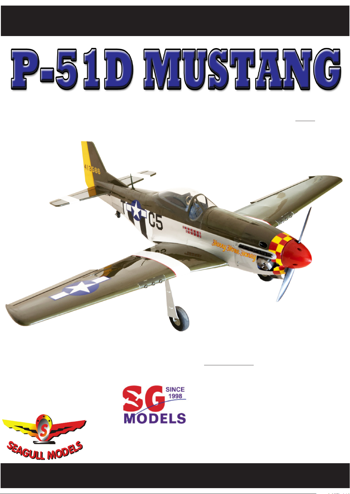
KIT CONTENTS.
HINGING THE FLAP.
SEA276 P-51D MUSTANG
1. Fuselage
2. Wing set
3. Tail set
4. Canopy
5. Cowling
6. Aluminium tube
7. Pilot
ADDITIONAL ITEMS REQUIRED.
� 10cc gasoline engine.
� Computer radio with 7 servos.
� Glow plug to suit engine.
� Propeller to suit engine.
� Protective foam rubber for radio
system.
Note : e control surfaces, including the ailerons, elevators, and rudder, are prehinged
with hinges installed, but the hinges are not
glued in place. It is imperative that you properly adhere the hinges in place per the steps
that follow using a high-quality thin C/A glue.
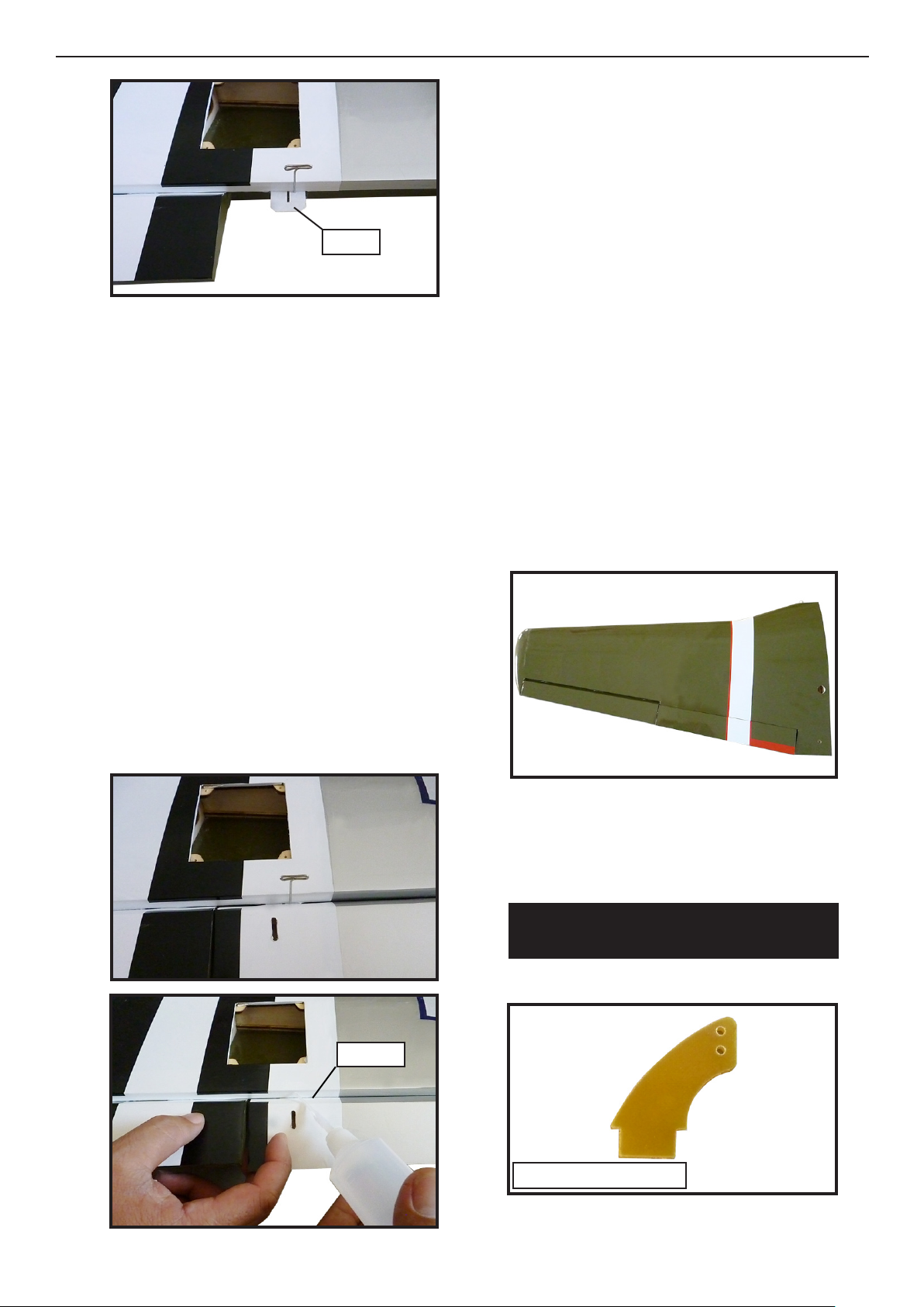
1) Carefully remove the ap from one of the
wing panels. Note the position of the hinges.
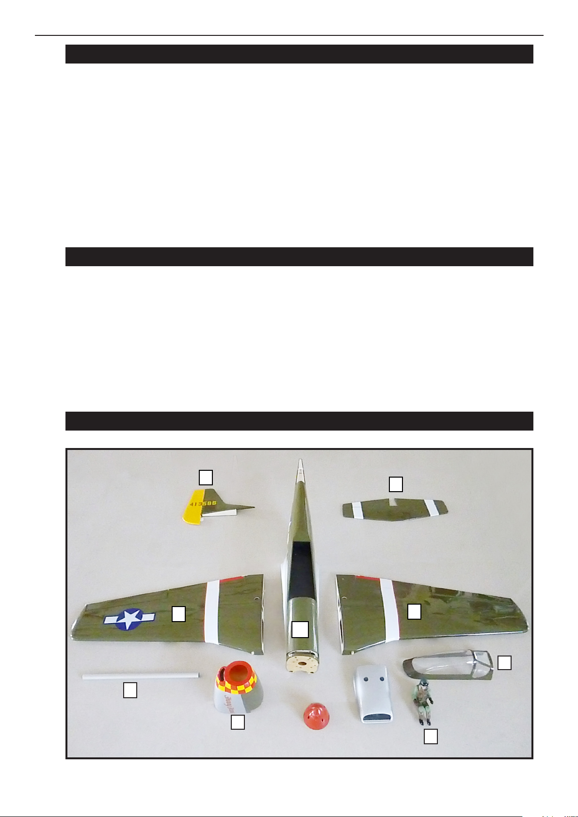
2) Remove each hinge from the wing panel
and ap and place a T-pin in the center of
each hinge. Slide each hinge into the wing
panel until the T-pin is snug against the wing
panel. is will help ensure an equal amount
of hinge is on either side of the hinge line
when the ap is mounted to the wing.
TOOLS & SUPPLIES NEEDED.
in cyanoacrylate glue.
Medium cyanoacrylate glue.
30 minute epoxy.
5 minute epoxy.
Hand or electric drill.
Assorted drill bits.
Modelling knife.
Straight edge ruler.
2mm ball driver.
Phillips head screwdriver.
220 grit sandpaper.
90° square or builder’s triangle.
Wire cutters.
Masking tape & T-pins.
read-lock.
Paper towels.
Hinge.
.
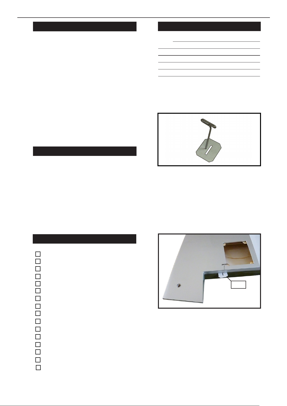
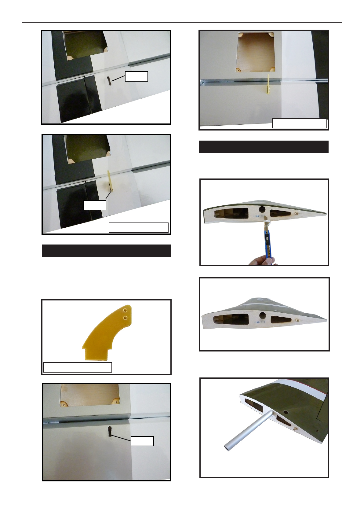
3) Slide the wing panel on the ap until there
is only a slight gap. e hinge is now centered
on the wing panel and ap. Remove the Tpins and snug the ap against the wing panel.
A gap of 1/64” or less should be maintained
between the wing panel and ap.
3
P-51D MUSTANG
Instruction Manual.
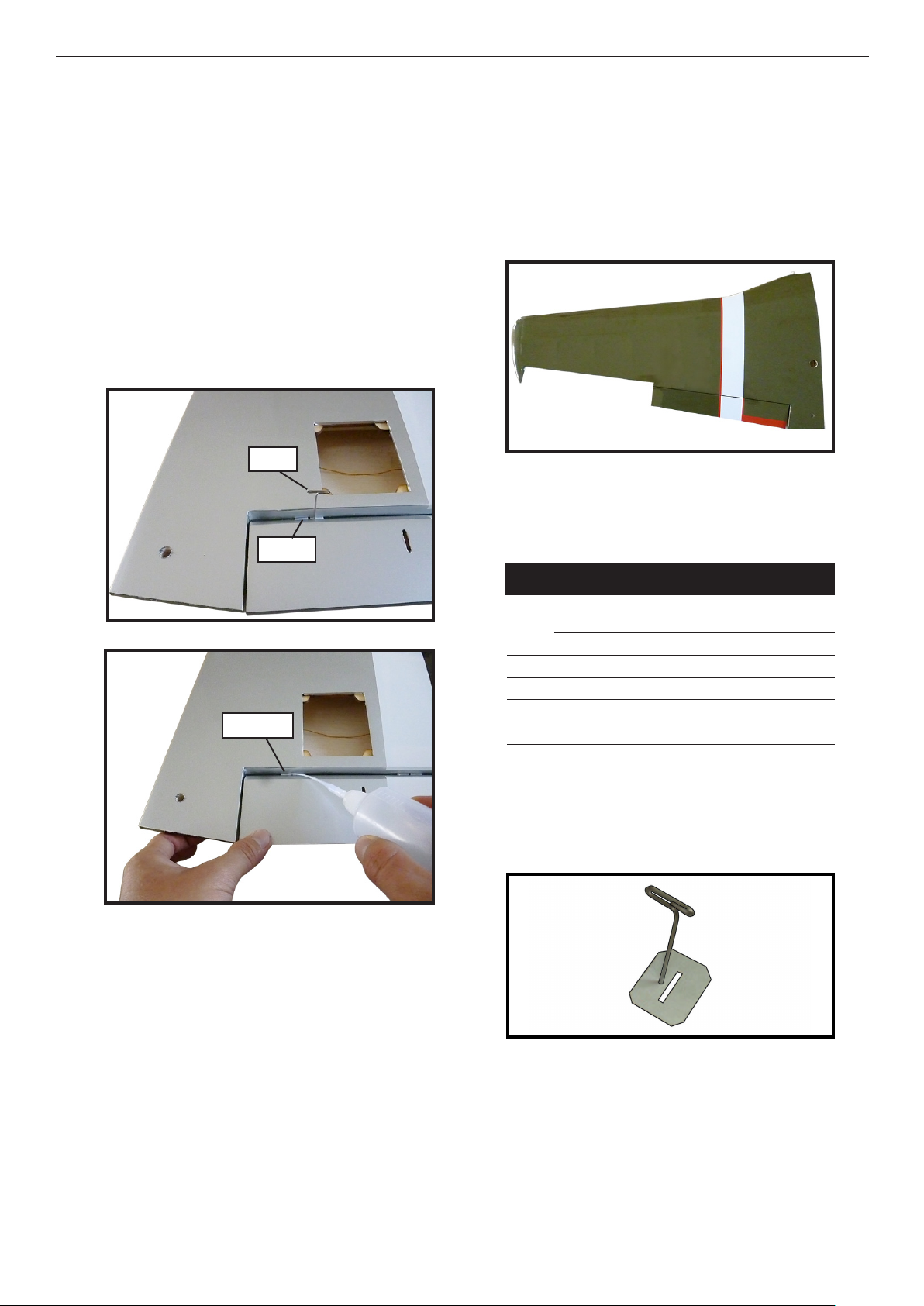
4) Deect the ap and completely saturate
each hinge with thin C/A glue. e ap’s
front surface should lightly contact the wing
during this procedure. Ideally, when the
hinges are glued in place, a 1/64” gap or less
will be maintained throughout the lengh of
the ap to the wing panel hinge line.
NOTE : e hinge is constructed of a special material that allows the C/A to wick
or penetrate and distribute throughout
the hinge, securely bonding it to the wood
structure of the wing panel and ap.
T-pin.
Hinge.
8) Aer both ap are securely hinged, rmly
grasp the wing panel and ap to make sure
the hinges are securely glued and cannot
be pulled out. Do this by carefully applying medium pressure, trying to separate the
ap from the wing panel. Use caution not to
crush the wing structure and/ or ap.
Note :
Work the ap up and down several
times to “work in” the hinges and
check for proper movement.
in CA.
5) Turn the wing panel over and deect the
ap in the opposite direction from the opposite side. Apply thin C/A glue to each hinge,
making sure that the C/A penetrates into
both the ap and wing panel.
HINGING THE AILERON.
Note : e control surfaces, including the ai-
lerons, elevators, and rudder, are prehinged
with hinges installed, but the hinges are not
glued in place. It is imperative that you properly adhere the hinges in place per the steps
that follow using a high-quality thin C/A glue.
1) Carefully remove the aileron from one
of the wing panels. Note the position of the
hinges.
6) Using C/A remover/debonder and a paper towel, remove any excess C/A glue that
may have accumulated on the wing or in the
ap hinge area.
7) Repeat this process with the other wing
panel, securely hinging the ap in place.
4
2) Remove each hinge from the wing panel
and aileron and place a T-pin in the center of
each hinge. Slide each hinge into the wing
panel until the T-pin is snug against the wing
panel. is will help ensure an equal amount
of hinge is on either side of the hinge line
when the aileron is mounted to the aileron.
Hinge.
3) Slide the wing panel on the aileron until
there is only a slight gap. e hinge is now
centered on the wing panel and aileron. Remove the T-pins and snug the aileron against
the wing panel. A gap of 1/64” or less should
be maintained between the wing panel and
aileron.
4) Deect the aileron and completely saturate each hinge with thin C/A glue. e ailerons front surface should lightly contact the
wing during this procedure. Ideally, when
the hinges are glued in place, a 1/64” gap or
less will be maintained throughout the lengh
of the aileron to the wing panel hinge line.
5) Turn the wing panel over and deect the
aileron in the opposite direction from the
opposite side. Apply thin C/A glue to each
hinge, making sure that the C/A penetrates
into both the aileron and wing panel.
6) Using C/A remover/debonder and a paper towel, remove any excess C/A glue that
may have accumulated on the wing or in the
aileron hinge area.
7) Repeat this process with the other wing
panel, securely hinging the aileron in place.
8) Aer both ailerons are securely hinged,
rmly grasp the wing panel and aileron to
make sure the hinges are securely glued and
cannot be pulled out. Do this by carefully applying medium pressure, trying to separate
the aileron from the wing panel. Use caution
not to crush the wing structure.
NOTE : e hinge is constructed of a special material that allows the C/A to wick
or penetrate and distribute throughout
the hinge, securely bonding it to the wood
structure of the wing panel and aileron.
in CA.
Note :
Work the aileron up and down several times to “work in” the hinges
and check for proper movement.
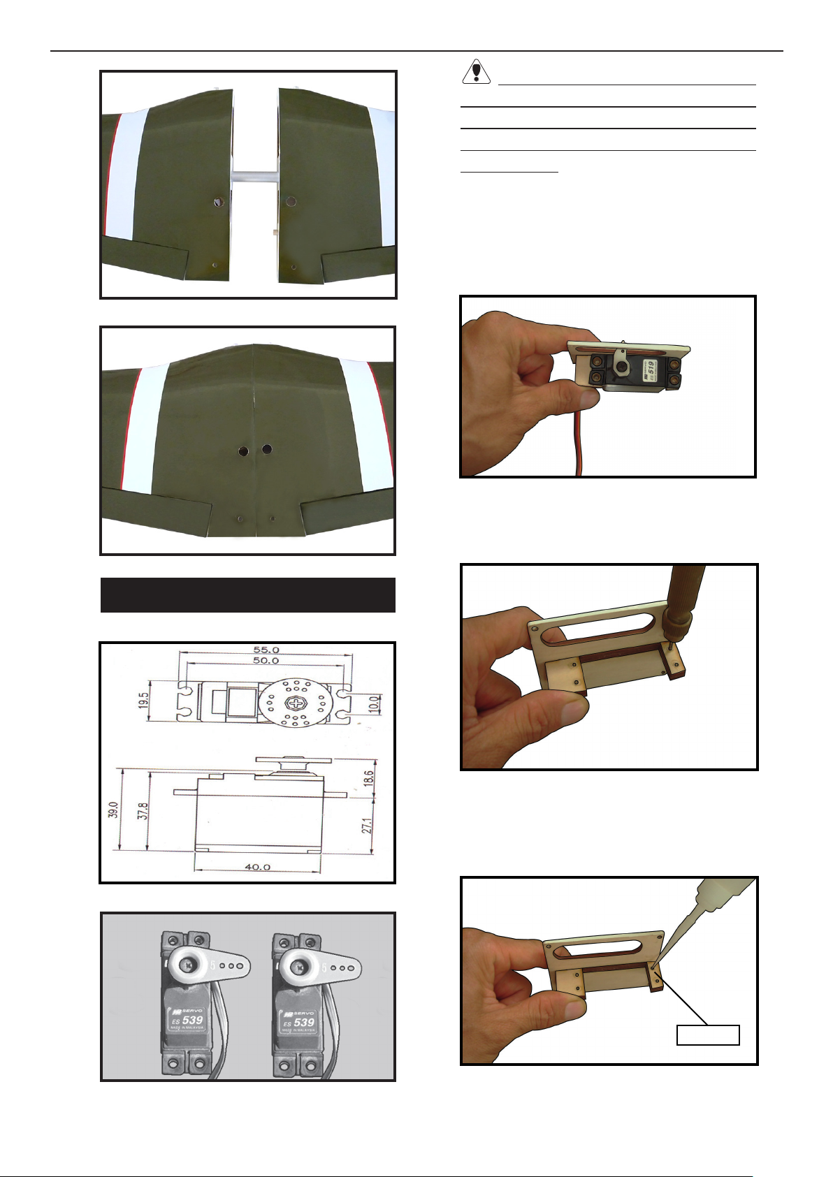
INSTALL THE AILERONS
CONTROL HORN.
Fiberglass control horn
5
P-51D MUSTANG
Instruction Manual.
Ep oxy.
Flap control horn.
WING ASSEMBLY.
Please see below pictures.
Ep oxy.
Aileron control horn.
INSTALL FLAP CONTROL HORN.
Install the ap control horn using the
same method as same as the aileron control horns.
Fiberglass control horn
Attach the aluminum tube into wing.
Ep oxy.
6
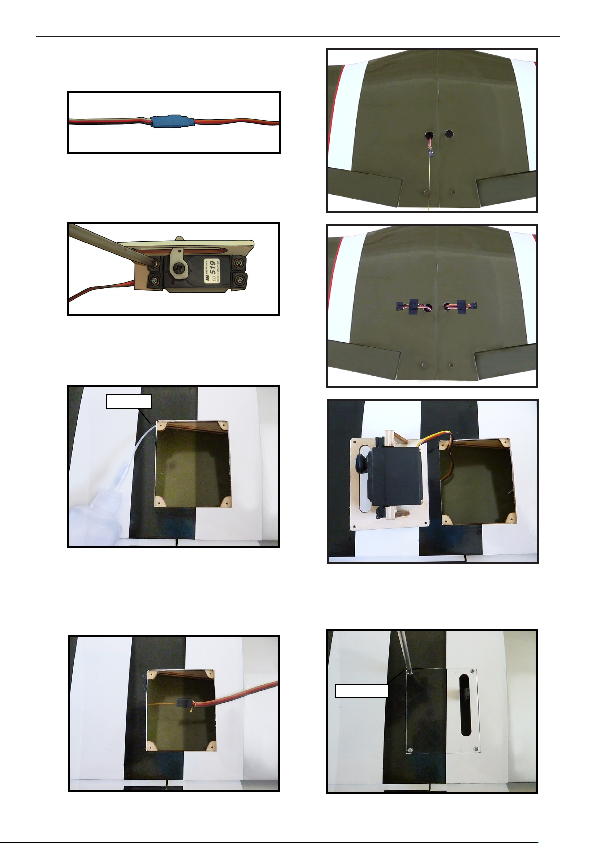
Because the size of servos dier, you
may need to adjust the size of the precut
opening in the mount. e notch in the
sides of the mount allow the servo lead to
pass through.
1) Place the servo between the mounting
blocks and space it from the hatch. Use a
pencil to mark the mounting hole locations on the blocks.
INSTALLING THE AILERON SERVOS.
2) Use drill bit in a pin vise to drill the
mouting holes in the blocks.
3) Apply 2-3 drops of thin C/A to each
of the mounting holes. Allow the C/A to
cure without using accelerator.
Servos
.
.
C/A glue
7
P-51D MUSTANG
4) Use dental oss to secure the connection so they cannot become unplugged.
5) Secure the servo to the aileron hatch
using Phillips screwdriver and the screws
provided with the servo.
Instruction Manual.
.
6) Apply 1-2 drops of thin C/A to each of
the mounting tabs. Allow the C/A to cure
without using accelerator.
C/A glue
7) Remove the string from the wing at
the servo location and use the tape to attach it to the servo extension lead. Pull
the lead through the wing and remove
8) Set the aileron hatch in place and use a
Phillips screw driver to install it with four
wood screws.
2x10mm
8
INSTALLING THE FLAP SERVO.
Mark.
Repeat the procedure for the ap servo.
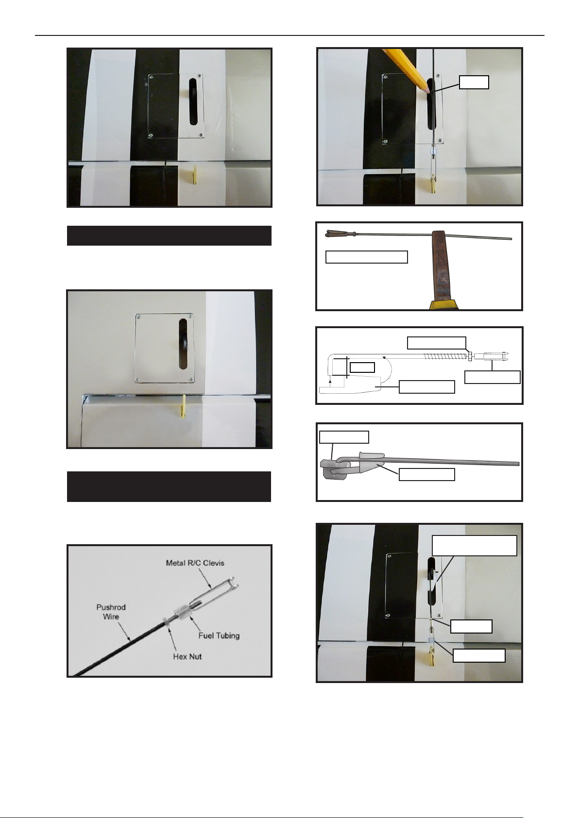
AILERON PUSHROD
INSTALLATION.
Please see below pictures.
Bend at the mark
M2 lock nut.
8mm
Metal clevis.
Snap keeper.
Servo arm.
Snap keeper.
.
Use a felt tip pen to mark the wire where
it crosses the hole. Use a pair of pliers to
put a shrp 90-degree bend in the wire at
the mark.
Nylon Snap keeper.
Hex Nut.
Fuel tubing.
9

P-51D MUSTANG
INSTALLING THE FLAP PUSHROD.
Repeat the procedure for the aileron
pushrod.
Instruction Manual.
STANDARD FIXED LANDING GEAR.
1) Remove the covering from the wing to
t the xed gear mounting blocks.
Mark.
Drill 2mm
10
Ep oxy.
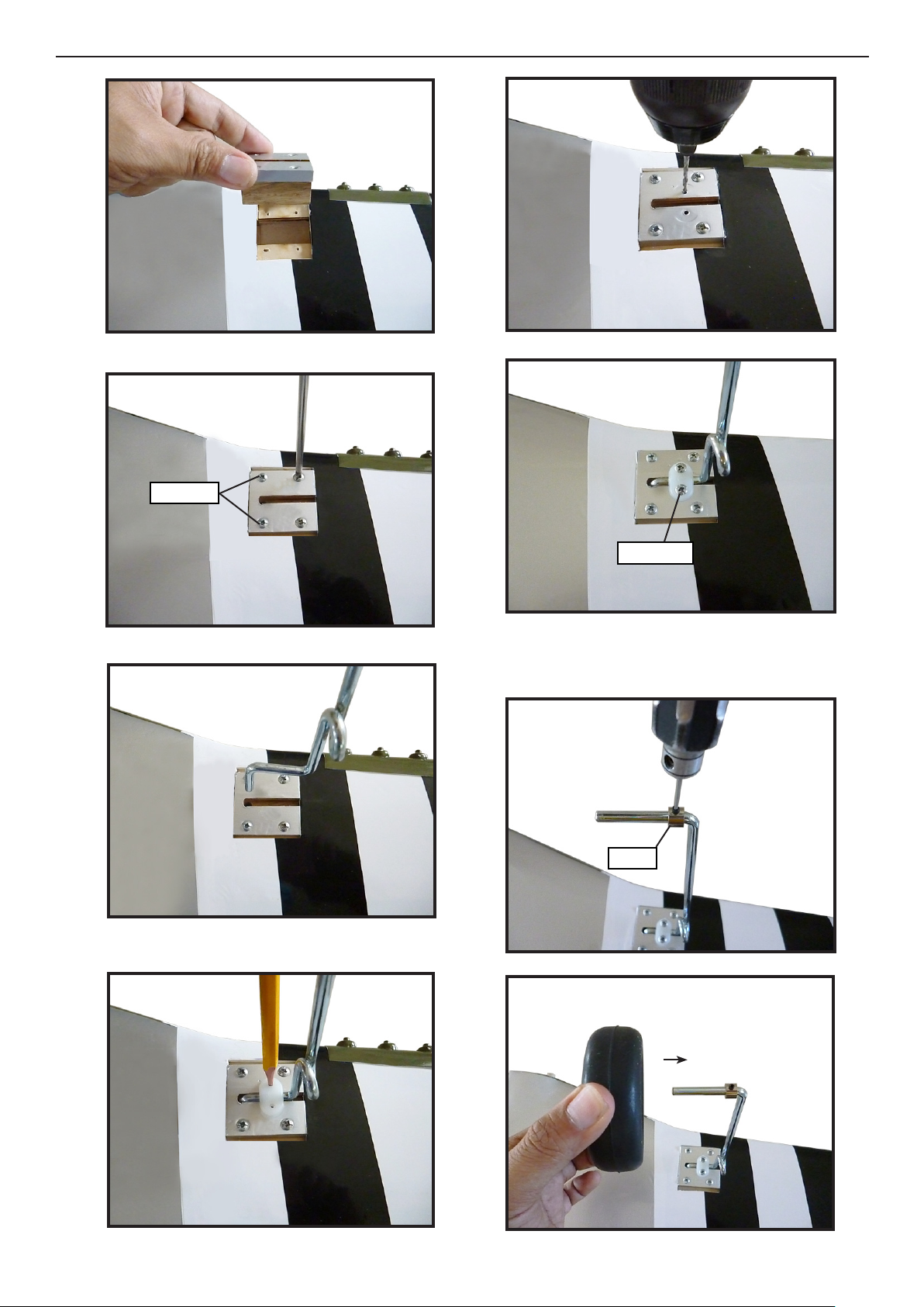
3x15mm
3x15mm
2) Slide the wheel on the axle, then secure
it using the wheel collar.
Collar.
11
 Loading...