

SG Models Skyraider Warbird 10CC, Skyraider Warbird 15CC, SEA230B Assembly Manual
Instruction Manual.
1
Specications:
Wingspan---------------63.0 in (160 cm).
Wing area---------------637.1 sq.in (41.1 sq.dm).
Weight-------------------8.6lbs (3.9 kg).
Length-------------------47.8 in (121.5cm).
Engine-------------------10cc - 15cc
Radio---------------------6 channels with 7 servos.
Electric conversion: Optional.
ASSEMBLY MANUAL
Code: SEA230B
“ Graphics and specications may change without notice ”.
( BEE VERSION )
ALMOST READY TO FLY

Skyraider WARBIRD 10cc-15cc
2
ank you for choosing the Skyraider WARBIRD 10cc-15cc ARF by SG MODELS . e
Skyraider WARBIRD 10cc-15cc was designed with the intermediate/advanced sport yer in
mind. It is a semi scale airplane which is easy to y and quick to assemble. e airframe is conventionally built using balsa, plywood to make it stronger than the average ARF, yet the design
allows the aeroplane to be kept light. You will nd that most of the work has been done for you
already. e motor mount has been tted and the hinges are pre-installed. Flying the Skyraider
WARBIRD 10cc-15cc is simply a joy.
is instruction manual is designed to help you build a great ying aeroplane. Please read this
manual throughly before starting assembly of your Skyraider WARBIRD 10cc-15cc . Use the
parts listing below to indentify all parts.
Please be aware that this aeroplane is not a toy and if assembled or used incorrectly it is
capable of causing injury to people or property. WHEN YOU FLY THIS AEROPLANE YOU
ASSUME ALL RISK & REPONSIBILITY.
If you are inexperienced with basic R/C ight we strongly recommend you contact your R/C
supplier and join your local R/C model Flying Club. R/C Model Flying Clubs oer a variety of
training procedures designed to help the new pilot on his way to successful R/C ight. ey
will also be able to advise on any insurance and safety regulations that may apply.
INTRODUCTION.
WARNING.
KIT CONTENTS
1
5
2
3
3
2
4
6
7
Instruction Manual.
3
KIT CONTENTS.
SEA230 Skyraider WARBIRD 10cc-15cc
SEA23001 Fuselage
SEA23002 Wing set
SEA23003 Tail set
SEA23004 Canopy
SEA23005 Pilot
SEA23006 Cowling
SEA23007 Aluminium tube
ADDITIONAL ITEMS REQUIRED.
10cc-15cc gasoline engine.
Computer radio with 7 servos.
Glow plug to suit engine.
Propeller to suit engine.
Protective foam rubber for radio
system.
TOOLS & SUPPLIES NEEDED.
ick cyanoacrylate glue.
30 minute epoxy.
5 minute epoxy.
Hand or electric drill.
Assorted drill bits.
Modelling knife.
Straight edge ruler.
2mm ball driver.
Phillips head screwdriver.
220 grit sandpaper.
90° square or builder’s triangle.
Wire cutters.
Masking tape & T-pins.
read-lock.
Paper towels.
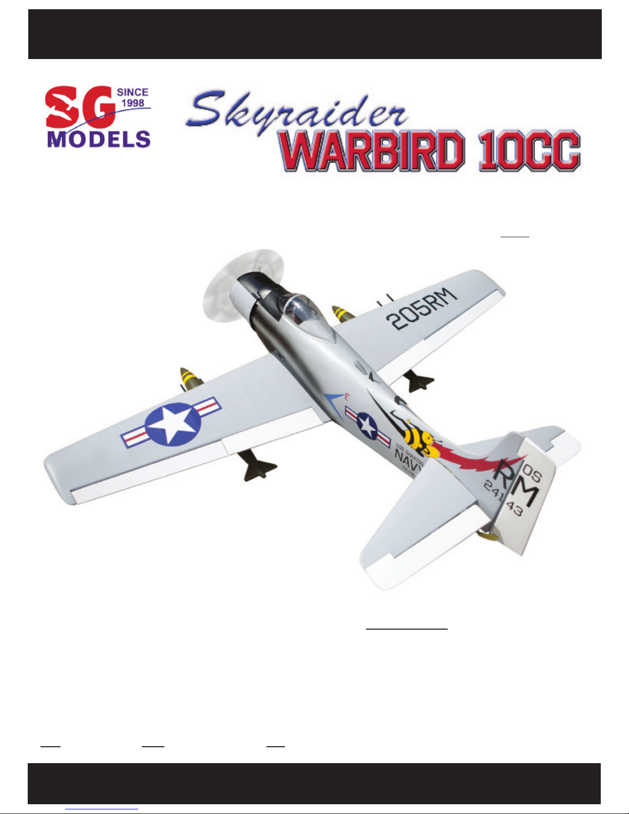
HINGING THE FLAP.
M2x10mm
M2x10mm
Skyraider WARBIRD 10cc-15cc
4
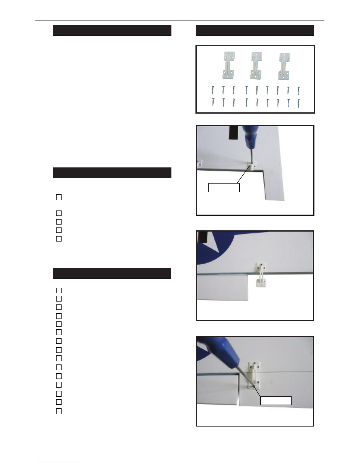
HINGING THE AILERON.
Note : e control surfaces, including the ai-
lerons, elevators, and rudder, are prehinged
with hinges installed, but the hinges are not
glued in place. It is imperative that you properly adhere the hinges in place per the steps
that follow using a high-quality thin C/A glue.
1) Carefully remove the aileron from one
of the wing panels. Note the position of the
hinges.
2) Remove each hinge from the wing panel
and aileron and place a T-pin in the center of
each hinge. Slide each hinge into the wing
panel until the T-pin is snug against the wing
panel. is will help ensure an equal amount
of hinge is on either side of the hinge line
when the aileron is mounted to the aileron.
3) Slide the wing panel on the aileron until
there is only a slight gap. e hinge is now
centered on the wing panel and aileron. Remove the T-pins and snug the aileron against
the wing panel. A gap of 1/64” or less should
be maintained between the wing panel and
aileron.
Hinge.
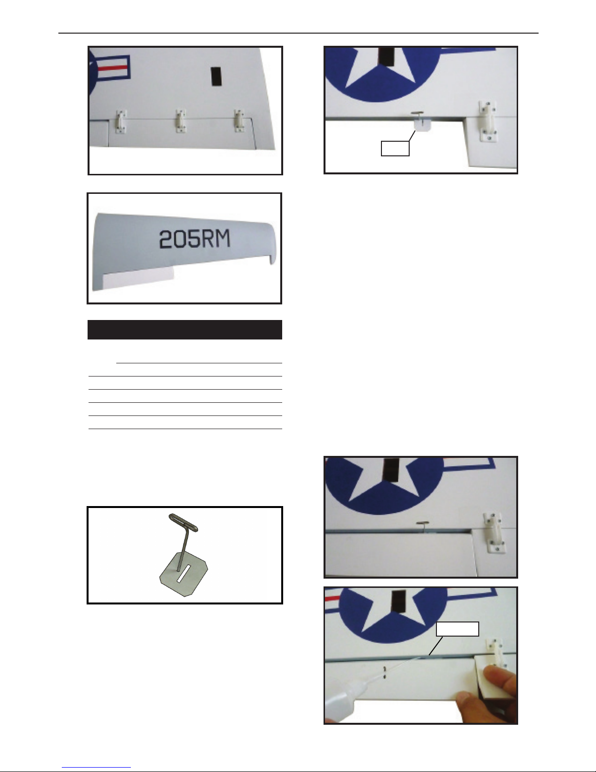
4) Deect the aileron and completely saturate each hinge with thin C/A glue. e ailerons front surface should lightly contact the
wing during this procedure. Ideally, when
the hinges are glued in place, a 1/64” gap or
less will be maintained throughout the lengh
of the aileron to the wing panel hinge line.
NOTE : e hinge is constructed of a special material that allows the C/A to wick
or penetrate and distribute throughout
the hinge, securely bonding it to the wood
structure of the wing panel and aileron.
C/A glue.

Instruction Manual.
5
5) Turn the wing panel over and deect the
aileron in the opposite direction from the
opposite side. Apply thin C/A glue to each
hinge, making sure that the C/A penetrates
into both the aileron and wing panel.
6) Using C/A remover/debonder and a paper towel, remove any excess C/A glue that
may have accumulated on the wing or in the
aileron hinge area.
7) Repeat this process with the other wing
panel, securely hinging the aileron in place.
8) Aer both ailerons are securely hinged,
rmly grasp the wing panel and aileron to
make sure the hinges are securely glued and
cannot be pulled out. Do this by carefully applying medium pressure, trying to separate
the aileron from the wing panel. Use caution
not to crush the wing structure.
Work the aileron up and down several times to “work in” the hinges
and check for proper movement.
Note :
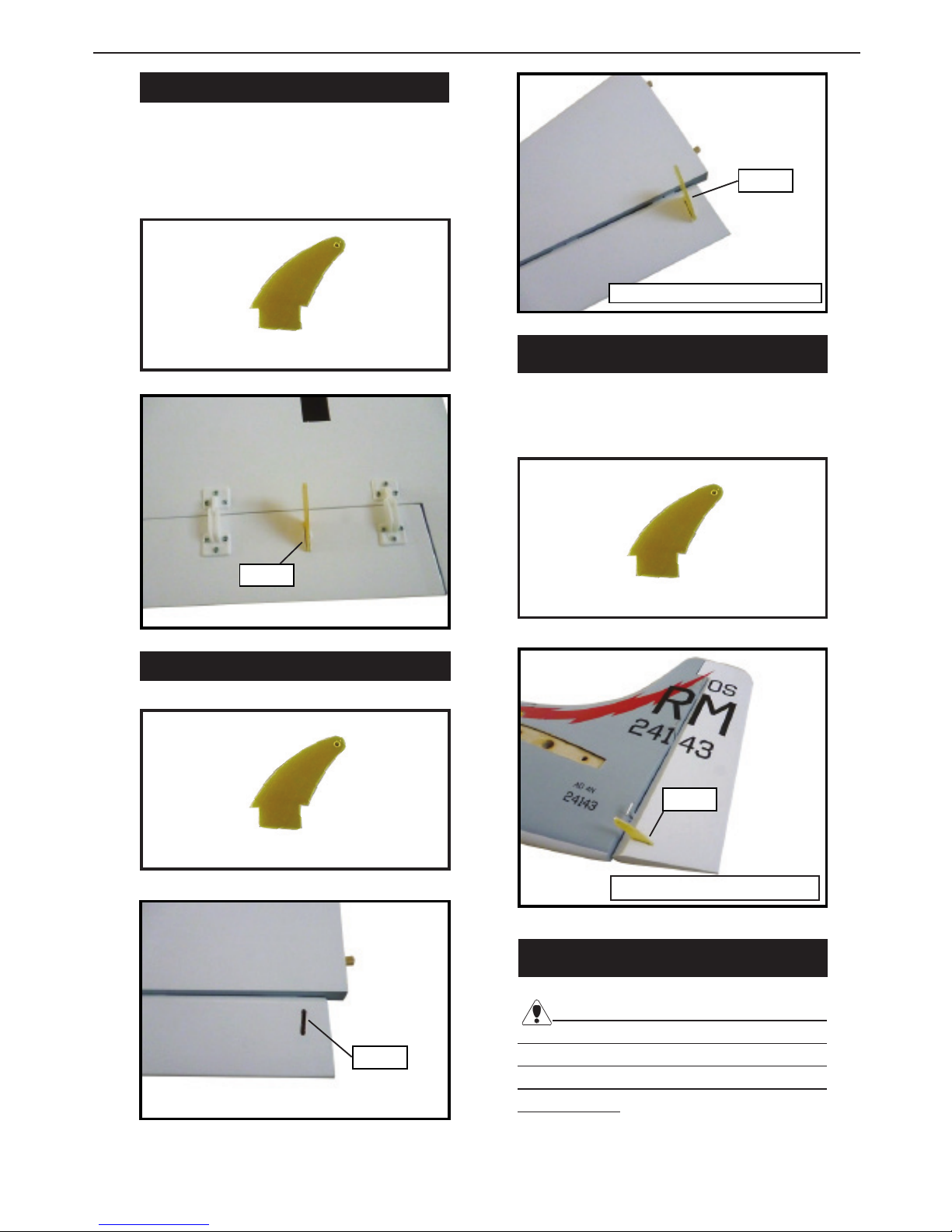
HINGING THE ELEVATORS.
Glue the elevator hinges in place using
the same techniques used to hinge the ailerons.
HINGING THE RUDDER.
Glue the rudder hinges in place using
the same techniques used to hinge the ailerons.
INSTALL THE AILERONS
CONTROL HORN.
Fiberglass control horn
Ep ox y.
Ep ox y.
Aileron control horn.
Skyraider WARBIRD 10cc-15cc
6
.
INSTALL FLAP CONTROL HORN.
Install the ap control horn using the
same method as same as the aileron control horns.
Ep ox y.
Elevator berglass control horn.
Ep ox y.
INSTALL RUDDER CONTROL HORN.
Repeat steps to install the rudder control
horn as same as steps done for ailerons.
INSTALL ELEVATOR CONTROL HORN.
Ep ox y.
Ep ox y.
Rudder berglass control horn.
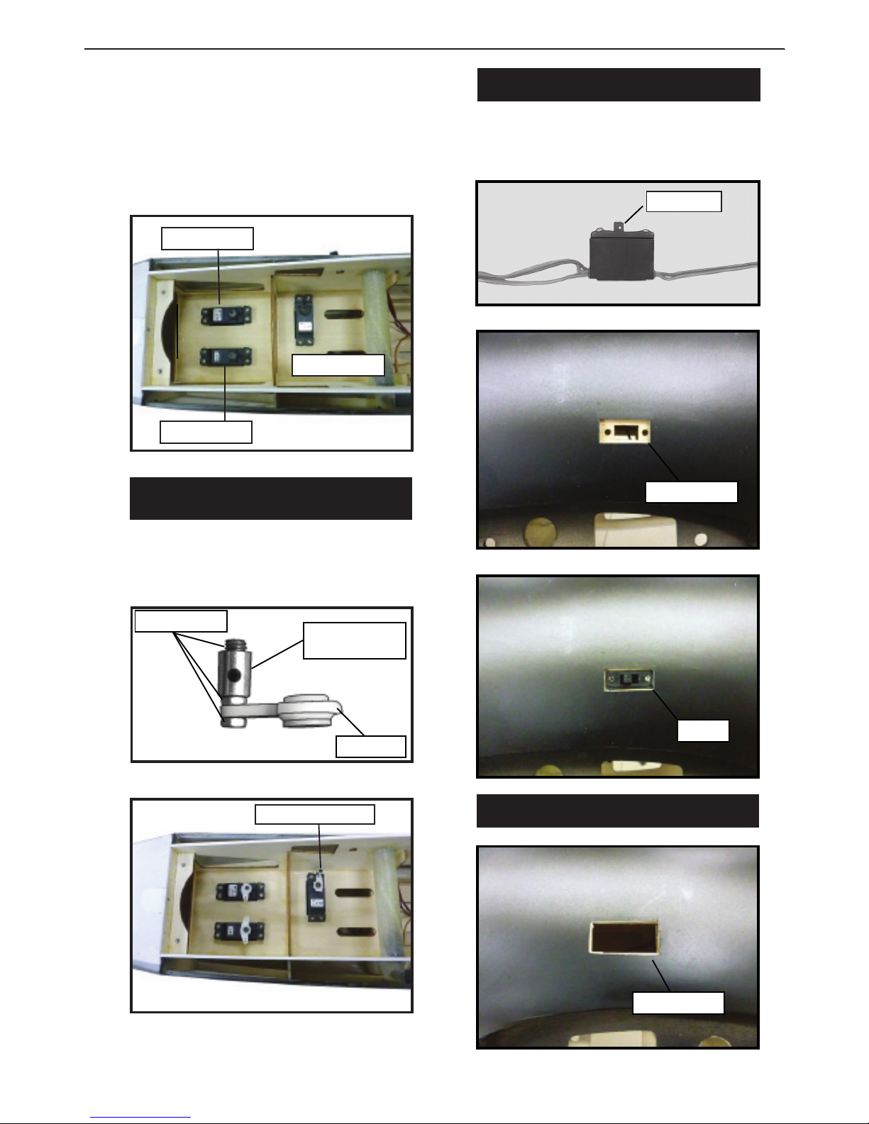
INSTALLING THE FUSELAGE SERVOS.
.
Because the size of servos dier, you
may need to adjust the size of the precut
opening in the mount. e notch in the
sides of the mount allow the servo lead to
pass through.
Fiberglass control horn.
Fiberglass control horn.
Fiberglass control horn.
Instruction Manual.
7
1) Install the rubber grommets and brass
collets onto the throttle servo. Test t the
servo into the aileron servo mount.
2) Secure the servos with the screws provided with your radio system.
Rudder servo.
Elevator servo.
rottle servo.
THROTTLE SERVO ARM
INSTALLATION.
Install adjustable servo connector in the
servo arm as same as picture below:
Servo arm.
Adjustable servo
connector.
Loctite secure.
rottle servo arm.
INSTALLING THE RECEIVER SWITCH.
Install the switch into the precut hole in
the side, in the fuselage.
3/32” Hole.
Trim and cut.
.
Switch.
INSTALLING THE ENGINE SWITCH.
Trim and cut.
Skyraider WARBIRD 10cc-15cc
8
Switch.
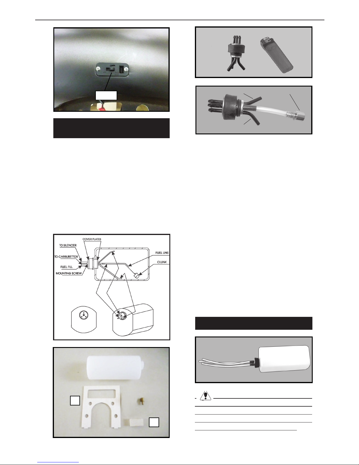
INSTALLING THE STOPPER
ASSEMBLY.
1) Using a modeling knife, carefully cut
o the rear portion of one of the 3 nylon
tubes leaving 1/2” protruding from the
rear of the stopper. is will be the fuel
pick up tube.
2) Using a modeling knife, cut one length
of silicon fuel line. Connect one end of
the line to the weighted fuel pick up and
the other end to the nylon pick up tube.
Vent tube.
Fuel pick up
Fuel fill tube.
3) Carefully bend the second nylon tube up
at a 45º angle. is tube is the vent tube.
4) Test t the stopper assembly into the tank.
It may be necessary to remove some of the
ashing around the tank opening using a
modeling knife. If ashing is present, make
sure none falls into the tank.
A
B
5) With the stopper assembly in place, the
weighted pick-up should rest away from the
rear of the tank and move freely inside the
tank. e top of the vent tube should rest just
below the top of the tank. It should not touch
the top of the tank.
6) When satised with the alignment of the
stopper assembly tighten the 3 x 20mm machine screw until the rubber stopper expands
and seals the tank opening. Do not overtighten the assembly as this could cause the
tank to split.
FUEL TANK INSTALLATION.
You should mark which tube is the vent
and which is the fuel pickup when you attach
fuel tubing to the tubes in the stopper. Once
the tank is installed inside the fuselage, it may
be dicult to determine which is which.
Instruction Manual.
9
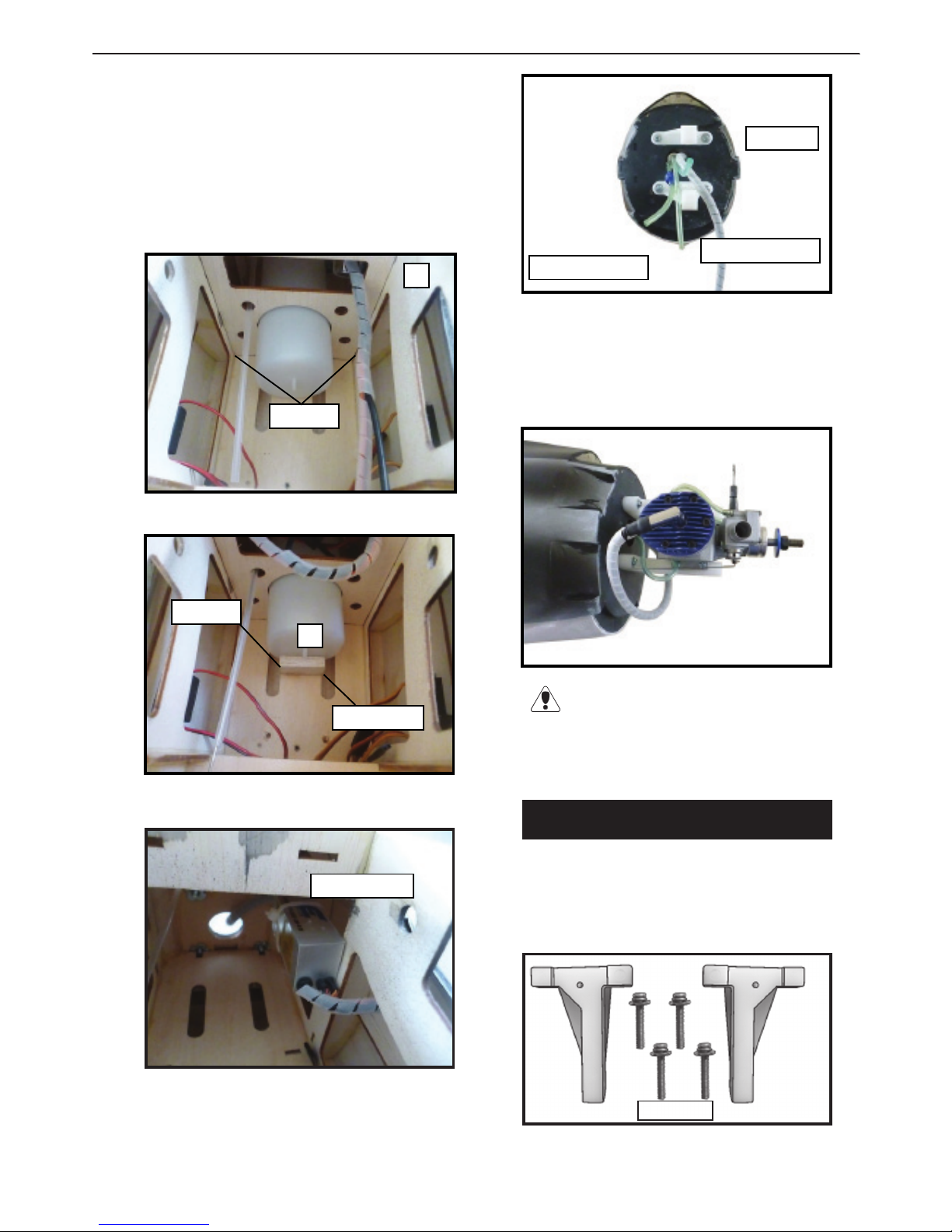
7) Slide the fuel tank into the fuselage. Guide
the lines from the tank through the hole in
the rewall.
8) Use plywood template to hold in place the
fuel tank with C/A glue to secure the fuel
tank inside the fuselage.
A
C/A glue.
C/A glue.
Balsa wood.
B
9) Connect the lines from the tank to the engine and muer. e vent line will connect
to the muer and the line from the clunk to
the carburetor.
Vent tube.
Fuel pick up tube.
Fuel ll tube.
Blow through one of the lines to ensure
the fuel lines have not become kinked inside
the fuel tank compartment. Air should ow
through easily.
.
ENGINE MOUNT INSTALLATION.
1) Locate the items necessary to install
the engine mount included with your
model.
4x30mm
Set of ignition.

Skyraider WARBIRD 10cc-15cc
10
2) Use four 4x30mm head bolts and four
4mm washers to attach the engine mount
rails to the rewall. Tighten the screws .
Make sure to use threadlock on the screws to
help prevent them from vibrating loose.
read locker glue.
MOUNTING THE ENGINE - 2 stroke.
1) Position the engine with the drive
washer (140mm) forward of the rewall
as shown.
140mm
2) Use a pin drill and 4mm drill bit to
drill a small indentation in the mount for
the engine mounting screw.
3) Use a drill to drill the four holes in the
engine mount rails.
4mm
4mm
4) On the re wall has the location for the
throttle pusshrod tube (pre-drill).
5) Slide the pushrod tube in the rewall
and guide it through the fuel tank mount.
Use medium C/A to glue the tube to the
rewall and the fuel tank mount.
6) Connect the Z-bend in the 450mm
throttle pushrod to the outer hole of the
carburetor arm.
7) Slide the throttle pushrod wire into
the tube. Position the engine between the
mounts. Use four M4x30mm machine
screws to secure the engine to the mount
as shown.
Machine screw M4x30mm
 Loading...