

Page 1
OPERATING INSTRUCTIONS
PLASTIC CENTRIFUGAL ROOF MOUNTED FANS
SDR 63.3 SIZES 355 – 710
Page 2

Issued: PA S Operating manual No. 28.95.103 Valid from: Serial No. 29956
Date: 01.03.2001 Plastic Radial Roof Mounted Fans
SDR 63 Sizes 355-710
1. General notes
This operating manual is valid for all plastic centrifugal roof
fans of series
SDR 63 Sizes 355 - 710
manufactured and supplied by SGL ACOTEC GmbH in
56427 Siershahn, Berggarten 1, Germany.
The instructions must be handed to the user, who has to
inform the people responsible for operation, servicing and
repair. No liability is accepted for damage resulting from
non-observance of the instructions.
The fans supplied by SGL ACOTEC are designed with
reference to the order on the basis of flow rate, total
pressure differential, medium, operating temperature and
installation site. The actual parameters are shown on the
machine card or rating plate.
The product supplied must only be used for the application
specified in the contract and within the scope of the
conversion possibilities listed in this operating manual. Any
other use is regarded as not in accordance with the
intended purpose. SGL ACOTEC do not accept liability for
any damage arising from such a use.
CONTENTS
1. General notes 2
2. Construction and operating principle 2- 3
3. Realization of the safety requirements 4
4. Transport/Storage 4
5. Installation 4
6. Drive 5
7. Installation of the motors 5
8. Commissioning 5
9. Inspection/Maintenance 6
2. Construction and operating principle
SGL ACOTEC Centrifugal Roof Mounted Fans of Series
SDR 63 have been designed as vertically discharging,
direct-drive feed appliances for corrosive gases and
vapours. The medium handled is drawn in axially by the
rotating impeller and by deflection downstream of the
horizontal impeller outlet again passed axially around the
enclosed motor and to the outlet branch.
SDR fans of sizes 355 - 710 are of welded construction
and consist of the following sub-assemblies: enclosure,
motor support, impeller, air intake and tubular liner. Motor
support as well as the top and bottom section of the
enclosure are welded together. For Sizes 355 and 400, 450
and 500 as well as 560 and 630, identical enclosures are
used respectively. This makes it possible to convert the
fans also after delivery and installation by changing the
impeller and air intake to the other respective size.
The motor support is designed for the installation of six
motor sizes (71 - 132) in the design B5. The motors are
screened against the medium; cooling air supply is via
ventilation hoses (fig. 1). The impellers used have eight
backward curved blades and are balanced electrodynamically in two planes. Minimum balancing quality Q 6.3 to
ISO 1940.
10. Servicing/Conversion 6
Appendix: Characteristics diagrams 8-11
2
Page 3
Issued: PA S Operating manual No. 28.95.103 Valid from: Serial No. 29956
Date: 01.03.2001 Plastic Radial Roof Mounted Fans
SDR 63 Sizes 355-710
Housing, motor support and impellers are made from
thermoplastics. The permissible operating temperatures of
the fans are with construction in
PVC 50°C
PP 70°C
and must not be exceeded.
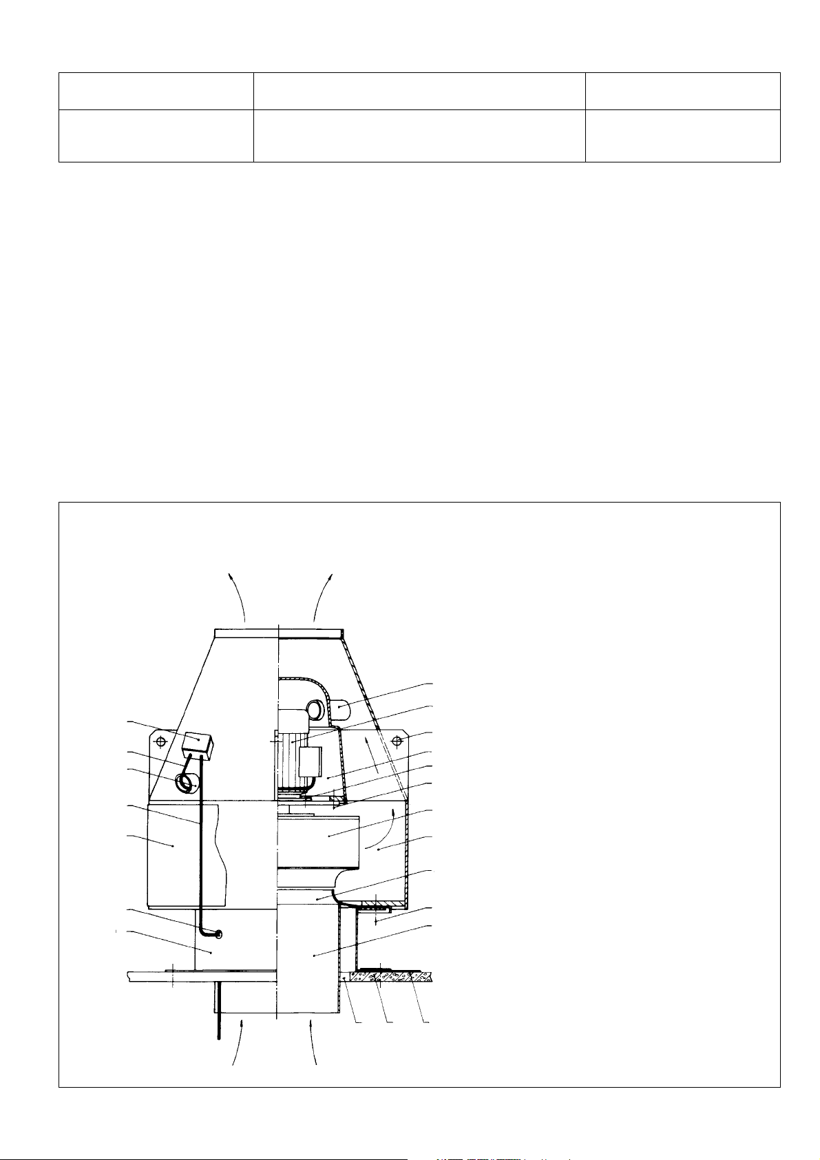
Fig. 1 SGL ACOTEC Centrifugal Roof Fan SDR, flat roof installation
12
10
8
11
6
13
14
7
9
18
2
19
20
3
1
4
21
5
1 – Housing
2 – Motor support
3 – Impeller
4 – Air intake
5 – Liner
6 – Splinter guard
7 – Upper ventilation hose
8 – Lower ventilation hose
9 – Motor
10 – Motor lead
11 – Fan supply cable
12 – Terminal box
13 – Moisture-proof union
14 – Roof mount
15 – Roof covering
16 – Roof penetration
17 – Roof liner
18 – Hitching point
19 – Fixing screw, motor
20 – Fixing screw, motor flange
21 – Fixing screw, fan
16
1715
3
Page 4
Issued: PA S Operating manual No. 28.95.103 Valid from: Serial No. 29956
Date: 01.03.2001 Plastic Radial Roof Mounted Fans
SDR 63 Sizes 355-710
3. Realization of the safety requirements
SGL ACOTEC Centrifugal Roof Mounted Fans Type SDR
are manufactured to the latest technological standards and
conform to the legal requirements in design, construction
and safety measures. If used in accordance with their
purpose and in compliance with this operating manual,
they are safe and reliable.
• All rotating parts are covered so that they cannot be
touched (motor enclosed, impeller screened by a
housing).
• On open-inlet fans the air intake is covered by a protective grille.
• The enclosures are radially surrounded by a splinter
guard, which if the impeller and/or housing are
damaged, prevents flying fragments.
• The enclosures and plastic impellers are welded in
accordance with the valid regulations. Welding additives
for thermoplastics conform to DVS 22.11.
• All impellers are statically and dynamically balanced
in two planes. Balancing quality min. Q 6.3 to ISO 1940.
The user of centrifugal roof fans supplied by SGL ACOTEC
has the following obligations:
• The fans must only be operated, serviced, converted
and repaired by authorized persons. These must be
instructed by the user in accordance with the operating
instructions about the correct procedure during the
above work and about possible angers.
• The user is obliged to operate the supplied product
only in sound condition.
• Unauthorised modifications which affect the function
and/ or safety of the fan are not permitted.
• All servicing, inspection, conversion and maintenance
operations must only be carried out with the fan at rest
and the power supply shut off.
• The removal of information-, instruction- and prohibition
plates from the product is not permissible. In all cases,
the fan must also be operated in accordance with all
local safety and accident prevention regulations.
4. Transport and storage
• The fans must be transported carefully and safely to
prevent damage through excessive force. Any impact-,
traction- or pressure stress on the plastic housings
must be avoided.
• When transported by truck, rail or ship, the fans must
be loaded and secured so that slipping, tilting or
friction are avoided.
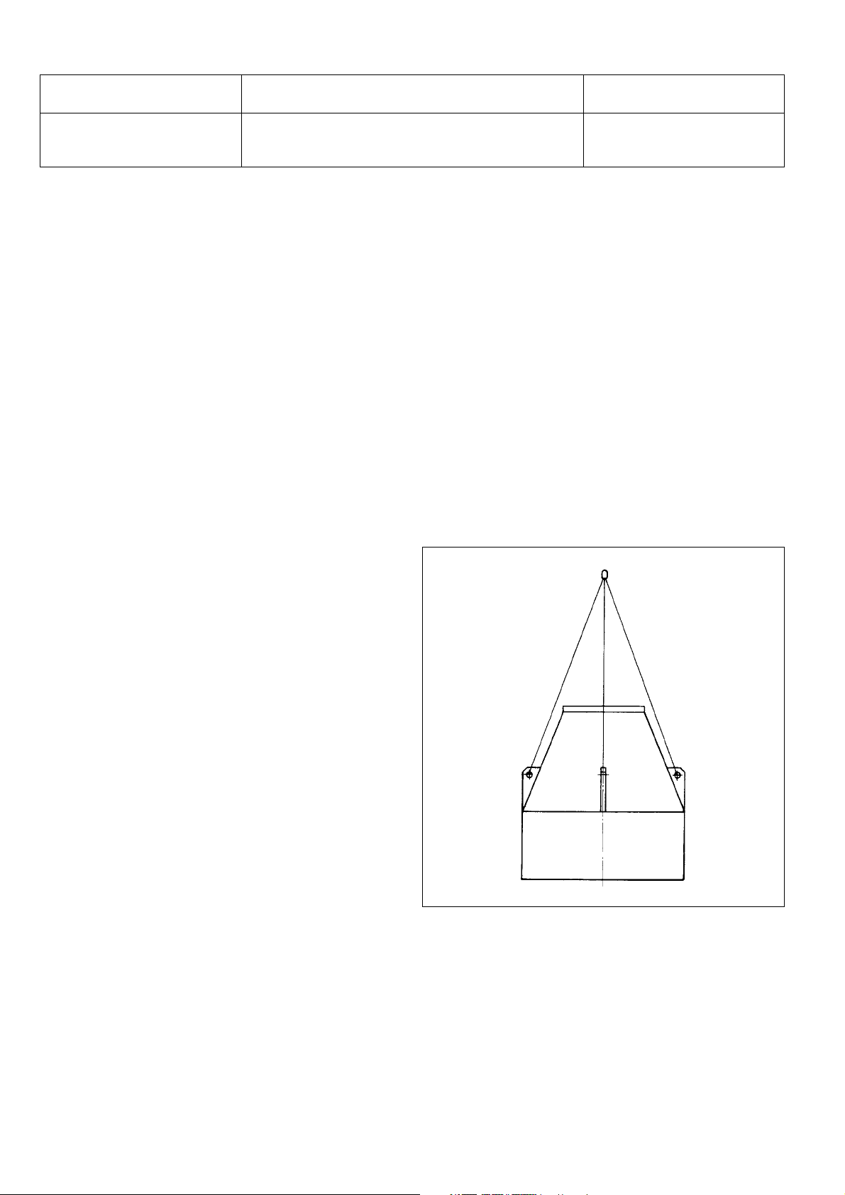
• The fans must be lifted and carried by means of fork-lift
truck or crane. When transported by crane, the fans
must be attached at the four plastic hitching eyes (fig. 2)
provided for that purpose.
To prevent damage of the eyes, shackles or fabric
attachments must be used.
The storage of the fans does not require any special
arrangements. They should be stored in rooms or on
roofed-over areas.
The discharge opening must be covered to prevent
objects from dropping into it. The fans must not be
stacked.
Fig. 2 SDR crane handling
5. Positioning
The SDR fans are placed on flat or sloping roofs by
installation on roof mounts, which are fixed onto the roof
covering and sealed with the roof liner (fig. 1).
• The intake-side duct must be connected to the liner
passing through the roof penetration and must only be
made with flexible connectors (bellows-type expansion
joints).
• Drive motor and terminal box at the top section of the
4
Page 5

Issued: PA S Operating manual No. 28.95.103 Valid from: Serial No. 29956
Date: 01.03.2001 Plastic Radial Roof Mounted Fans
SDR 63 Sizes 355-710
housing are ready wired before the fans are
dispatched.
• The supply to the fan terminal box must be laid between liner and roof mount and sealed at the wall
penetration by means of a heavy-gauge moisture-proof
union.
6. Drive
• As standard, the centrifugal roof fans are driven by threephase a.c. motors to IEC recommendation, type of
enclosure IP54 or EExe, design B5.
If required, motors for other voltages and frequencies,
pole-reversing or also variable-speed motors are used.
• The centrifugal roof fans are in principle supplied with
the drive motor fitted. The test run after final installation
confirms the performance and operational safety of the
fan.
• If the motor is installed by the customer, the manufacturer’s product liability does not apply.
7. Installation of the motors
• When installing the electrical wiring for the motors and
any necessary switchgear, the VDE (German electrical
engineers’ association) regulations and the motor
manufacturer’s instructions must be observed.
• The installation is made according to the wiring diagram
contained in the terminal box and must only be carried
out by appropriately qualified technical personnel.
Check voltage, rpm and direction of rotation. Direction
of rotation of the motor must conform to the rotation
symbol on the fan enclosure.
• When using pole-reversing motors, a further change
from high to low speed must be provided. The delayed
switching must be bumpless.
• A motor protection facility must be provided on principle.
If the fans are installed in positions where the temperature
of the cooling air exceeds 40oC, a performance reduction
of the motors must be taken into account. Values are
shown in the catalogues of the motor manufacturers.
8. Commissioning
Commissioning and operation of the fans must only be
carried out by appropriately trained persons who are familiar
with the applicable operating and safety regulations. After
installation of the fan and connection of the suction-side duct
system as in Item 5, the following must be checked or carried
out:
• All visible screw connections must be checked for
tightness.
• Protective devices must be checked for proper attachment (casing splinter protection, with open-inlet fans
intake protection grille).
• Check motor venting hoses and the condensate drain
bore in the housing base for clear passage.
• Foreign bodies (forgotten tools or installation material
etc.) must be removed from the internal spaces of the
fan and from the upstream ducts and assemblies.
• All possibly existing regulating elements (gate valves,
butterfly valves) must be sufficiently closed before
starting so that only approx. 10% of the cross-section
remains open.
When starting the fan, proceed as follows:
• Expel unauthorized personnel from the fan area!
• Switch on the main switch and the motor switch (note
permissible motor starting frequency).
• After nominal speed has been reached, open any control
elements until the required working point establishes
itself.
After starting, pay special attention to:
• Power input of the motor
• Quiet running of the fan.
After 12 hours of operation, check all visible screw
connections for firm seating and retighten if necessary.
5
Page 6

Issued: PA S Operating manual No. 28.95.103 Valid from: Serial No. 29956
Date: 01.03.2001 Plastic Radial Roof Mounted Fans
SDR 63 Sizes 355-710
9. Inspection / Maintenance
The reliability and service life of the fans depend also on
correct inspection and maintenance. Fans in continuous
and trouble-free operation must be checked every three
months as follows:
• Visual check for cracks and/or fractures in the fan enclosure caused by vibration.
• Visual inspection of the impeller for wear and/or cakedondeposits caused by abrasive media.
• Inspection of the duct connections for tightness.
The inspection of the ventilation orifices and the condensate
drain bore as in Item 8, para. 3, should be carried out at fairly
short intervals to be determined by the user.
SGL ACOTEC Centrifugal Roof Mounted Fans are
maintenance-free, the bearings of the motors are generally
permanently lubricated for their nominal service life.
10. Servicing / Conversion
Fans are machines which should be provided with preventive
and condition-oriented servicing to avoid breakdowns and
lengthy downtimes as far as possible.
The servicing operations must be carried out with reference to
the safety instructions as in Item 3 and the applicable
operational protection at work instructions, and must only
be carried out by authorized and qualified persons who
are familiar with this operating manual.
Below, only work is described which must be carried out
within the scope of the replacement of original parts
(e.g. impeller) or when converting the fan.
Important!
Before starting work, stop the fan, switch off the main
switch and secure against unintentional or unauthorized
switching on again!
10.1 Removal / installation of the impeller
Removal becomes necessary in case of wear, fracture or
imbalance of the impeller as well as during the conversion
of a fan size to another one (e.g. SDR 63-355 to SDR 630400 or vice versa). Specified component numbering acc.
to fig. 1.
• Disconnect the supply (11) at the terminal box (12)
• Remove the nuts of the six fixing screws (21) and lift off
the fan. Air intake and liner (4, 5) remain in the assembled
condition on the roof mount (14).
• Turn the fan and place with the discharge opening
downwards.
• After removing the plug and unscrewing the fixing
screw, the impeller (3) can extracted from the motor
shaft.
• Assembly is in the reverse order.
10.2 Changing impeller and liner
This becomes necessary when converting the fan to a
different size, e.g. SDR 63-355 to 400, SDR 63-450 to 500
or vice versa.
• Removal of the impeller as in Item 10.1
• Remove the suction-side duct connection from the
liner (5) and remove the air intake with liner (4, 5) from
the roof mount (14).
• Assemble the replaced components in reverse order.
6
Page 7

Issued: PA S Operating manual No. 28.95.103 Valid from: Serial No. 29956
Date: 01.03.2001 Plastic Radial Roof Mounted Fans
SDR 63 Sizes 355-710
10.3 Changing the motor
• Remove the impeller as in Item 10.1.
• Disconnect the motor lead (10) at the terminal box (12).
• Remove the six fixing screws (2) and lift the motor (9)
out of the motor support (2). After removing the four
motor fixing screws (19), the motor (9) can be lifted off
the support flange.
• Installation in the reverse order. When positioning the
motor (9) in the motor support (2), the motor lead (10)
must be passed through the lower fan hose (8).
• All unused motor fixing bores in the support flange must
be sealed with PE plugs (GPN 300 V7, V10, V041).
Note!
For conversion of the fans only original components must
be used. The selection of the drive motors must be made
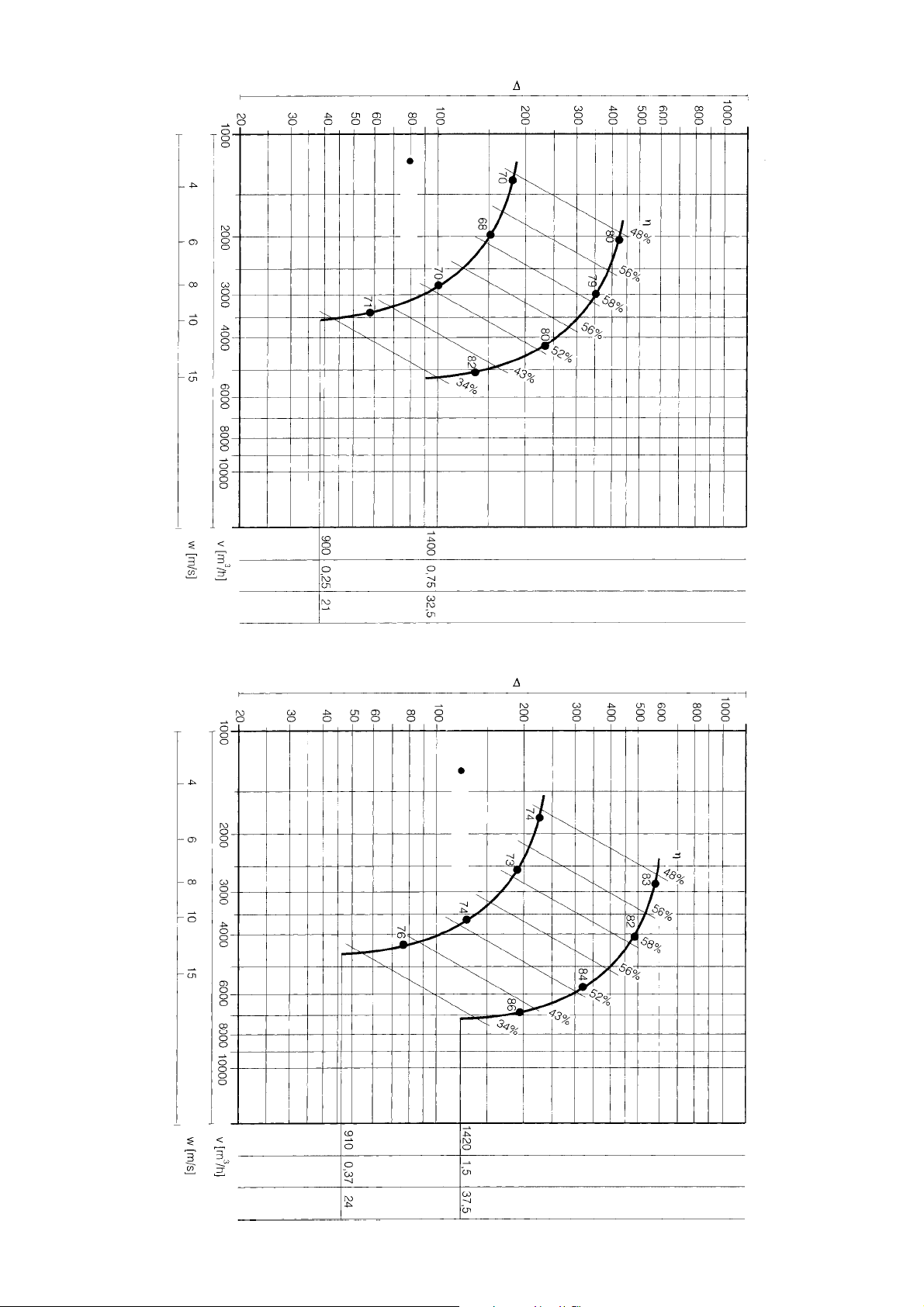
according to the respective characteristic diagrams.
Consultation with the fan manufacturer is recommended
prior to each conversion.
11. Wear parts
On SGL ACOTEC Centrifugal Roof Mounted Fans, the
impellers are wear parts.
Impellers of sizes 355 - 710 are made to order and are
therefore not kept in stock. Sufficient delivery periods must
be allowed for by the customer for ordering replacements.
7
Page 8
8
Total pressure differential
Noise level [dB]
pt [Pa]
SDR 63 – 355
Characteristics
Total pressure differential
Noise level [dB]
pt [Pa]
Fan speed [rpm]
Motor output [kW]
Circumferential velocity [m/s]
SDR 63 – 400
Characteristics
Fan speed [rpm]
Motor output [kW]
Circumferential velocity [m/s]
Page 9
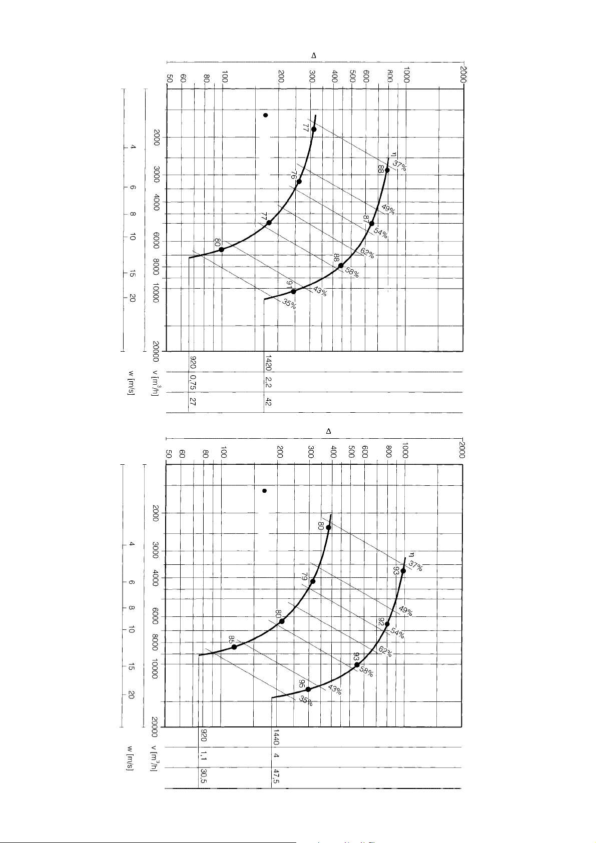
9
Total pressure differential
Noise level [dB]
pt [Pa]
SDR 63 – 450
Characteristics
Total pressure differential
Noise level [dB]
pt [Pa]
Fan speed [rpm]
Motor output [kW]
Circumferential velocity [m/s]
SDR 63 – 500
Characteristics
Fan speed [rpm]
Motor output [kW]
Circumferential velocity [m/s]
Page 10
10
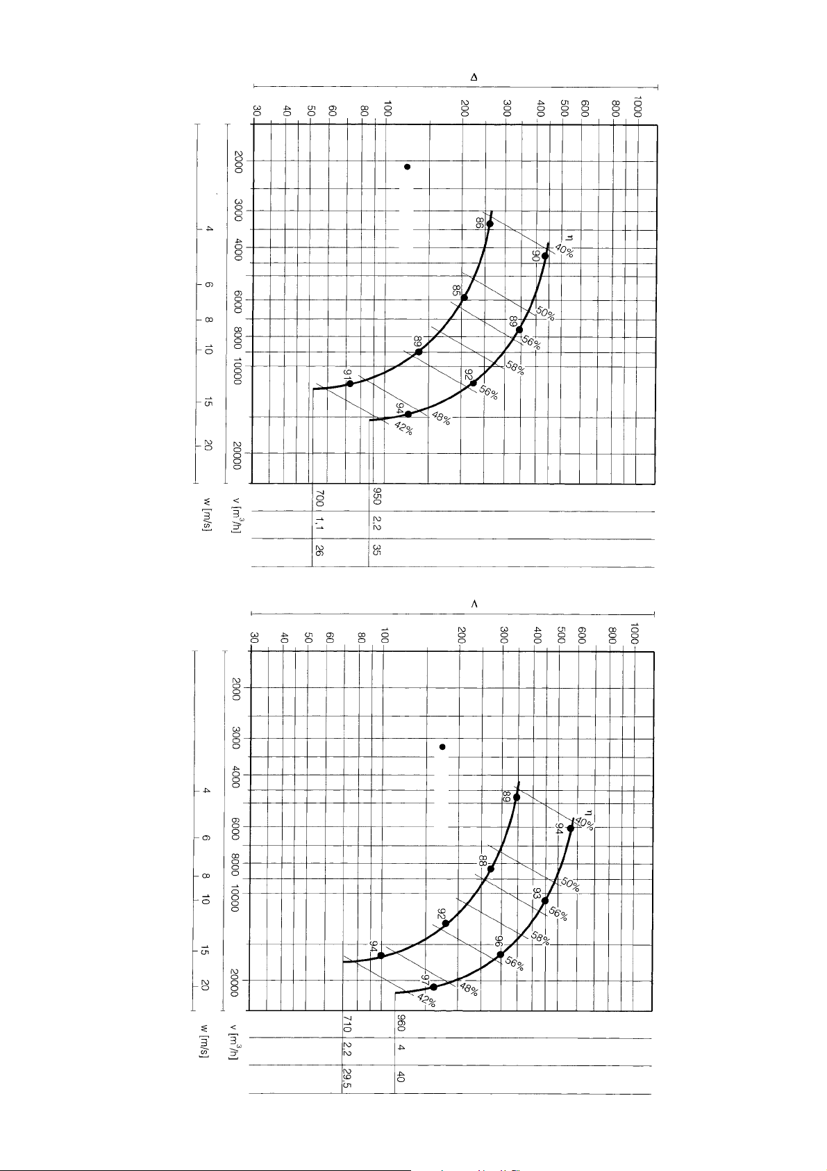
Total pressure differential
Noise level [dB]
pt [Pa]
SDR 63 – 560
Characteristics
Total pressure differential
Noise level [dB]
Fan speed [rpm]
Motor output [kW]
Circumferential velocity [m/s]
pt [Pa]
SDR 63 – 630
Characteristics
Fan speed [rpm]
Motor output [kW]
Circumferential velocity [m/s]
Page 11
11
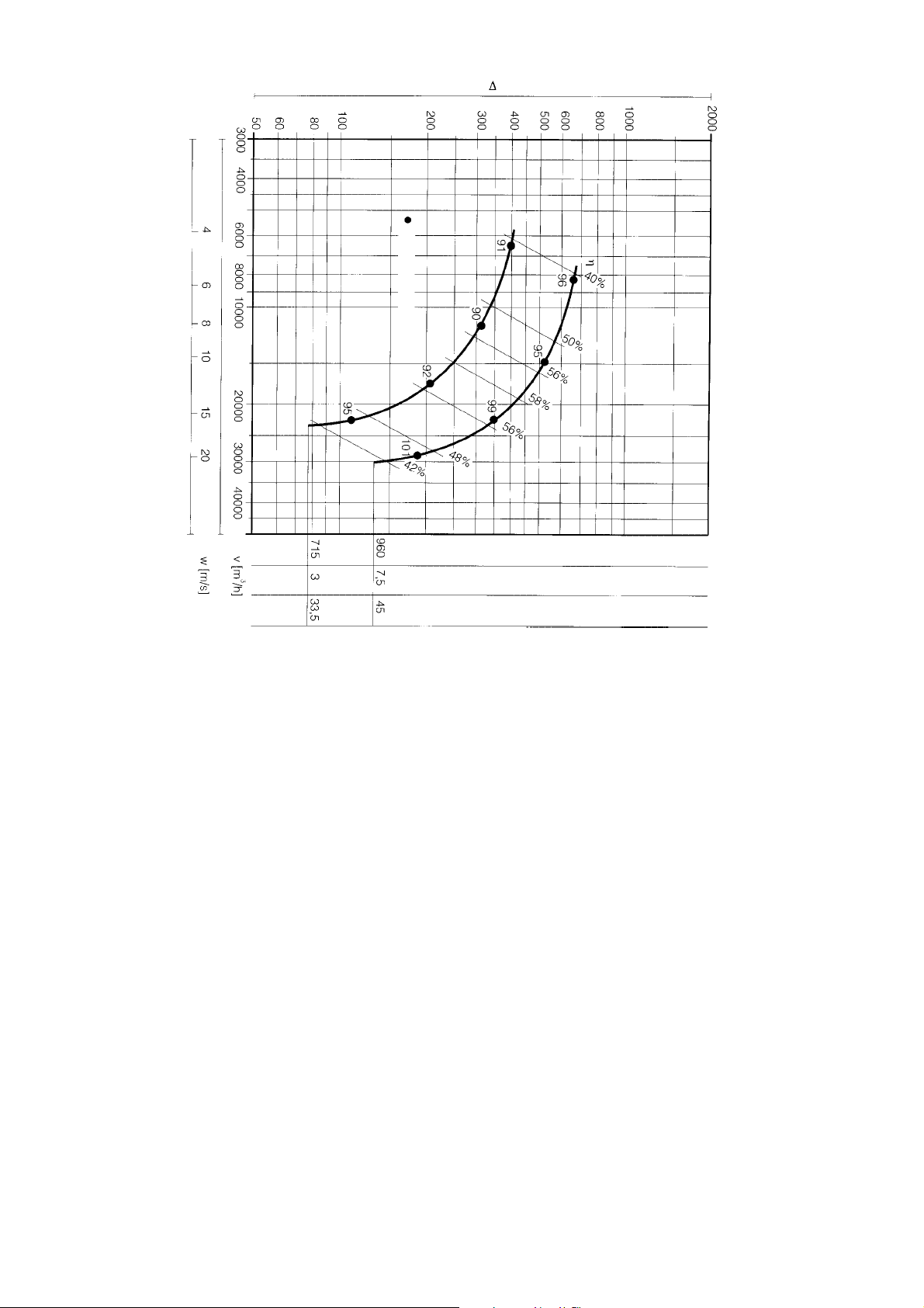
Total pressure differential
Noise level [dB]
pt [Pa]
SDR 63 – 710
Characteristics
Fan speed [rpm]
Motor output [kW]
Circumferential velocity [m/s]
Page 12

© SGL ACOTEC GmbH, Siershahn (Germany), 2000
® registered trademarks of SGL CARBON GROUP
companies
This information is based on our present state of knowledge
and is intended to provide general notes on our products and
their uses. It should therefore not be construed as guaranteeing
specific properties of the products described or their suitability
for a particular application. Any, existing industrial property
rights must be observed. The quality of our products is
guaranteed under our “General Conditions of Sale”.
Corrosion Protection
Business Unit
SGL ACOTEC GmbH
Berggarten 1
D-56427 Siershahn
Phone +49 (26 23) 6 00-0
Fax +49 (26 23) 6 00-7 91
[email protected]
www.sglcarbon.com
 Loading...