

Page 1
SGI® UV 3000 System User Guide
Document Number 007-6402-001
Page 2

COPYRIGHT
© 2015 SGI. All rights reserved; provided portions may be copyright in third parties, as indicated elsewhere herein. No permission is granted to copy, distribute,
or create derivative works from the contents of this electronic documentation in any manner, in whole or in part, without the prior written permission of SGI.
LIMITED RIGHTS LEGEND
The software described in this document is "commercial computer software" provided with restricted rights (except as to included open/free source) as specified
in the FAR 52.227-19 and/or the DFAR 227.7202, or successive sections. Use beyond license provisions is a violation of worldwide intellectual property laws,
treaties and conventions. This document is provided with limited rights as defined in 52.227-14.
The electronic (software) version of this document was developed at private expense; if acquired under an agreement with the USA government or any
contractor thereto, it is acquired as “commercial computer software” subject to the provisions of its applicable license agreement, as specified in (a) 48 CFR
12.212 of the FAR; or, if acquired for Department of Defense units, (b) 48 CFR 227-7202 of the DoD FAR Supplement; or sections succeeding thereto.
Contractor/manufacturer is SGI, 900 North McCarthy Blvd. Milpitas, CA 95035.
TRADEMARKS AND ATTRIBUTIONS
Silicon Graphics, SGI, the SGI logo, NUMAlink, NUMAflex, FullCare, FullExpress, and HardwareCare are trademarks or registered trademarks of Silicon
Graphics International Corp. or its subsidiaries in the United States and/or other countries worldwide.
Intel, Itanium and Xeon are trademarks or registered trademarks of Intel Corporation or its subsidiaries in the United States and other countries.
UNIX is a registered trademark in the United States and other countries, licensed exclusively through X/Open Company, Ltd.
Infiniband is a trademark of the InfiniBand Trade Association.
LSI, MegaRAID, and MegaRAID Storage Manager are trademarks or registered trademarks of LSI Corporation.
Linux is a registered trademark of Linus Torvalds in the U.S. and other countries.
Red Hat and all Red Hat-based trademarks are trademarks or registered trademarks of Red Hat, Inc. in the United States and other countries.
SUSE LINUX is a registered trademark of Novell Inc.
Windows is a registered trademark of Microsoft Corporation in the United States and other countries.
All other trademarks mentioned herein are the property of their respective owners.
Page 3

Record of Revision
Version Description
-001 August, 2015
First Release
007-6402-001 iii
Page 4

Page 5

Contents
List of Figures . . . . . . . . . . . . . . . . . . . . . . . . xi
List of Tables . . . . . . . . . . . . . . . . . . . . . . . . xiii
Audience. . . . . . . . . . . . . . . . . . . . . . . . . . xv
Important Information . . . . . . . . . . . . . . . . . . . . . . xv
Chapter Descriptions . . . . . . . . . . . . . . . . . . . . . . xvi
Related Publications . . . . . . . . . . . . . . . . . . . . . . .xvii
Conventions . . . . . . . . . . . . . . . . . . . . . . . . . xix
Product Support . . . . . . . . . . . . . . . . . . . . . . . . xx
Reader Comments . . . . . . . . . . . . . . . . . . . . . . . xx
1. Operation Procedures . . . . . . . . . . . . . . . . . . . . . . 1
Precautions . . . . . . . . . . . . . . . . . . . . . . . . . 1
ESD Precaution . . . . . . . . . . . . . . . . . . . . . . . 1
Safety Precautions . . . . . . . . . . . . . . . . . . . . . . 2
Power Connections Overview . . . . . . . . . . . . . . . . . . . . 2
Preparing to Power On . . . . . . . . . . . . . . . . . . . . . 3
SGI UV 3000 PDUs . . . . . . . . . . . . . . . . . . . . . 4
North America PDU Options . . . . . . . . . . . . . . . . . . 4
International PDU Options. . . . . . . . . . . . . . . . . . . 5
Additional PDU Overview information . . . . . . . . . . . . . . . 5
System Connections Overview . . . . . . . . . . . . . . . . . . . . 8
Connecting to the UV System Control Network . . . . . . . . . . . . . . 8
RMC System Control Access . . . . . . . . . . . . . . . . . . . 9
007-6402-001 v
Page 6

Contents
UV 3000 System Connections . . . . . . . . . . . . . . . . . . . . 10
Serial Port Connection to the RMC . . . . . . . . . . . . . . . . . . 10
USB-Connected Console Hardware Requirements. . . . . . . . . . . . . 11
Ethernet (LAN) Connection to the RMC . . . . . . . . . . . . . . . . 11
Establishing RMC IP Hardware Connections . . . . . . . . . . . . . . . 12
Using DHCP to Establish an IP Address . . . . . . . . . . . . . . . 12
Using a Static IP Address . . . . . . . . . . . . . . . . . . . 13
Controlling the UV 3000 System . . . . . . . . . . . . . . . . . . . 13
UV 3000 IPMI 2.x Administration Overview . . . . . . . . . . . . . . . 13
Power On Example Using the RMC Network Connection . . . . . . . . . . . . 14
The Command Line Interface . . . . . . . . . . . . . . . . . . . 14
Example CLI Commands Used. . . . . . . . . . . . . . . . . . 15
Powering On and Off from the Command Line Interface . . . . . . . . . . . . 16
Power On Example . . . . . . . . . . . . . . . . . . . . . 16
Power Down Example . . . . . . . . . . . . . . . . . . . . 16
Reset System Example . . . . . . . . . . . . . . . . . . . . 16
Power Status Check Example . . . . . . . . . . . . . . . . . . 16
Monitoring Power On Example . . . . . . . . . . . . . . . . . . . 16
Power off an SGI UV 3000 System . . . . . . . . . . . . . . . . . . 17
Optional In-Rack Console Server and Flat-Panel Interface . . . . . . . . . . . . . 19
Optional In-Rack Console Server . . . . . . . . . . . . . . . . . . 19
Optional SGI Remote Services (SGI RS) . . . . . . . . . . . . . . . . . 21
SGI Remote Services Primary Capabilities . . . . . . . . . . . . . . . . 22
SGI Remote Services Benefits . . . . . . . . . . . . . . . . . . . 22
SGI Remote Service Operations Overview . . . . . . . . . . . . . . . . 22
Optional Components . . . . . . . . . . . . . . . . . . . . . . 24
PCIe Cards . . . . . . . . . . . . . . . . . . . . . . . . 24
PCIe Drive Controllers in BaseIO Blade . . . . . . . . . . . . . . . . 26
RAID PCIe Disk Controller . . . . . . . . . . . . . . . . . . 26
Non-RAID PCIe Disk Controller . . . . . . . . . . . . . . . . . 27
vi 007-6402-001
Page 7

Contents
2. System Control . . . . . . . . . . . . . . . . . . . . . . . . 29
Levels of System Control . . . . . . . . . . . . . . . . . . . . . 29
RMC and System Management Overview . . . . . . . . . . . . . . . . 30
CMC Overview . . . . . . . . . . . . . . . . . . . . . . . 31
BMC Overview . . . . . . . . . . . . . . . . . . . . . . . 32
System Controller Interaction . . . . . . . . . . . . . . . . . . . . 33
IRU Controllers . . . . . . . . . . . . . . . . . . . . . . . . 34
Chassis Management Controller Functions. . . . . . . . . . . . . . . . 34
1U Console Plus Admin Server Option . . . . . . . . . . . . . . . . 34
Flat Panel Rackmount Console Option Features . . . . . . . . . . . . . 35
3. System Overview . . . . . . . . . . . . . . . . . . . . . . . 37
System Models . . . . . . . . . . . . . . . . . . . . . . . . 39
System Architecture . . . . . . . . . . . . . . . . . . . . . . . 41
System Features . . . . . . . . . . . . . . . . . . . . . . . . 43
Modularity and Scalability . . . . . . . . . . . . . . . . . . . . 43
Distributed Shared Memory (DSM) . . . . . . . . . . . . . . . . . 43
Distributed Shared I/O . . . . . . . . . . . . . . . . . . . . . 45
Chassis Management Controller (CMC) . . . . . . . . . . . . . . . . 45
ccNUMA Architecture . . . . . . . . . . . . . . . . . . . . . 45
Cache Coherency . . . . . . . . . . . . . . . . . . . . . 45
Non-uniform Memory Access (NUMA) . . . . . . . . . . . . . . . 46
Reliability, Availability, and Serviceability (RAS) . . . . . . . . . . . . . 46
System Components . . . . . . . . . . . . . . . . . . . . . . . 48
Optional BaseIO SSDs . . . . . . . . . . . . . . . . . . . . . 50
MIC/GPU Enabled Compute Blade . . . . . . . . . . . . . . . . . 51
Bay (Unit) Numbering . . . . . . . . . . . . . . . . . . . . . 52
Rack Numbering . . . . . . . . . . . . . . . . . . . . . . 52
Optional System Components . . . . . . . . . . . . . . . . . . . 52
4. Rack Information . . . . . . . . . . . . . . . . . . . . . . . 53
Overview . . . . . . . . . . . . . . . . . . . . . . . . . 53
SGI UV 3000 Series Rack (42U) . . . . . . . . . . . . . . . . . . . 54
SGI UV 3000 42U System Rack Technical Specifications . . . . . . . . . . . . . 58
007-6402-001 vii
Page 8

Contents
The 24U (Short) Rack . . . . . . . . . . . . . . . . . . . . . . 59
5. Optional Octal Router Chassis Information . . . . . . . . . . . . . . . . 61
Overview . . . . . . . . . . . . . . . . . . . . . . . . . . 61
SGI UV 3000 Series NUMAlink Octal Router Chassis . . . . . . . . . . . . . . 62
SGI UV 3000 External NUMAlink System Technical Specifications . . . . . . . . . . 64
6. Add or Replace Procedures . . . . . . . . . . . . . . . . . . . . 65
Maintenance Precautions and Procedures . . . . . . . . . . . . . . . . . 65
Preparing the System for Maintenance or Upgrade . . . . . . . . . . . . . . 66
Returning the System to Operation . . . . . . . . . . . . . . . . . . 66
Removing and Replacing an IRU Enclosure Power Supply . . . . . . . . . . . . . 67
Replacing a System Fan (Blower) . . . . . . . . . . . . . . . . . . . 69
Replacing a Blade-Mounted Drive . . . . . . . . . . . . . . . . . . . 72
7. Troubleshooting and Diagnostics . . . . . . . . . . . . . . . . . . . 75
Troubleshooting Chart . . . . . . . . . . . . . . . . . . . . . . 76
LED Status Indicators . . . . . . . . . . . . . . . . . . . . . . 77
IRU Power Supply LEDs . . . . . . . . . . . . . . . . . . . . 77
Compute/Memory Blade LEDs . . . . . . . . . . . . . . . . . . . 78
SGI Electronic Support . . . . . . . . . . . . . . . . . . . . . . 79
SGI Remote Services (SGI RS) . . . . . . . . . . . . . . . . . . . 79
SGI Knowledgebase . . . . . . . . . . . . . . . . . . . . . . 79
SGI Warranty Levels . . . . . . . . . . . . . . . . . . . . . 79
A. Technical Specifications and Pinouts . . . . . . . . . . . . . . . . . . 81
System-level Specifications . . . . . . . . . . . . . . . . . . . . . 81
Physical Specifications . . . . . . . . . . . . . . . . . . . . . . 82
Environmental Specifications . . . . . . . . . . . . . . . . . . . . 83
Power Specifications . . . . . . . . . . . . . . . . . . . . . . . 84
I/O Port Specifications . . . . . . . . . . . . . . . . . . . . . . 85
BaseIO VGA Port Information . . . . . . . . . . . . . . . . . . . 85
Ethernet Port. . . . . . . . . . . . . . . . . . . . . . . . 87
Serial Ports . . . . . . . . . . . . . . . . . . . . . . . . 88
USB Type A Connector . . . . . . . . . . . . . . . . . . . . . 90
viii 007-6402-001
Page 9

Contents
B. Safety Information and Regulatory Specifications . . . . . . . . . . . . . . 91
Safety Information . . . . . . . . . . . . . . . . . . . . . . . 91
Regulatory Specifications . . . . . . . . . . . . . . . . . . . . . 93
CMN Number . . . . . . . . . . . . . . . . . . . . . . . 93
CE Notice and Manufacturer’s Declaration of Conformity . . . . . . . . . . . 93
Electromagnetic Emissions . . . . . . . . . . . . . . . . . . . . 94
FCC Notice (USA Only) . . . . . . . . . . . . . . . . . . . 94
Industry Canada Notice (Canada Only) . . . . . . . . . . . . . . . 95
VCCI Notice (Japan Only). . . . . . . . . . . . . . . . . . . 95
Korean Class A Regulatory Notice . . . . . . . . . . . . . . . . 95
Shielded Cables . . . . . . . . . . . . . . . . . . . . . . . 96
Electrostatic Discharge . . . . . . . . . . . . . . . . . . . . . 96
Laser Compliance Statements . . . . . . . . . . . . . . . . . . . 97
Lithium Battery Statement . . . . . . . . . . . . . . . . . . . . 98
007-6402-001 ix
Page 10

Page 11

List of Figures
Figure 1-1 UV 3000 Blade Enclosure Power Supply and Cable Location Example . 3
Figure 1-2 Single-Phase 8-Outlet PDU Example . . . . . . . . . . 6
Figure 1-3 Three-Phase PDU Example . . . . . . . . . . . . . 7
Figure 1-4 SGI UV RMC Front Panel Connections Example . . . . . . . 9
Figure 1-5 RMC Ethernet LAN (WAN Port) and CNSL Location Example . . . 11
Figure 1-6 Optional In-Rack Console Server Example (Front View) . . . . . 19
Figure 1-7 Optional (In-Rack) Administrative Console Server Rear View Example . 20
Figure 1-8 Flat Panel Rackmount Console Interface Option . . . . . . . 21
Figure 1-9 SGI Remote Services Process Overview. . . . . . . . . . 23
Figure 1-10 PCIe Option Blade Example with Full-Height and Low-Profile Slots . . 25
Figure 1-11 PCIe Option Blade Example with Two Low-Profile Slots . . . . . 25
Figure 1-12 BaseIO Blade and PCIe Disk Controller Example . . . . . . . 26
Figure 2-1 RMC Node Front Panel Example . . . . . . . . . . . 31
Figure 2-2 SGI UV 3000 LAN-attached Remote System Control Example . . . 32
Figure 2-3 Optional 1U Rackmount Console . . . . . . . . . . . 35
Figure 2-4 Optional (In-Rack) 1U System Administration Node Rear View . . . 36
Figure 3-1 SGI UV 3000 D-Rack System and Front Lock Example . . . . . 38
Figure 3-2 SGI UV 3000 IRU and Rack Example . . . . . . . . . . 40
Figure 3-3 Functional Block Diagram of the Individual Rack Unit (IRU) . . . . 42
Figure 3-4 SGI UV 3000 Blade Nodes Block Diagram Example . . . . . . 44
Figure 3-5 SGI UV 3000 IRU System Components Example . . . . . . . 49
Figure 3-6 BaseIO Riser Enabled Blade Front Panel Example . . . . . . . 50
Figure 3-7 MIC/GPU Enabled Compute Blade Example Front View . . . . . 51
Figure 4-1 SGI UV Air-cooled D-Rack Example (Rear Lock Shown) . . . . . 55
Figure 4-2 Front Lock on Tall (42U) Rack . . . . . . . . . . . . 56
Figure 4-3 Optional Water-Chilled Cooling Units on Rear of SGI 42U Rack . . . 57
Figure 4-4 UV 24U (Short) Rack Example Front View . . . . . . . . . 59
007-6402-001 xi
Page 12

List of Figures
Figure 4-5 SGI 24U (Short) Rack Rear View Example . . . . . . . . . 60
Figure 5-1 SGI UV 3000 Optional NUMAlink ORC (Rear View) . . . . . . 62
Figure 5-2 SGI UV 3000 Optional ORC Chassis Example (Front View) . . . . 63
Figure 6-1 Removing an Enclosure Power Supply . . . . . . . . . . 67
Figure 6-2 Replacing an IRU Enclosure Power Supply . . . . . . . . . 68
Figure 6-3 UV 3000 Rear Fan Assembly (Blowers) . . . . . . . . . . 70
Figure 6-4 Removing a Fan From the Rear Assembly . . . . . . . . . 71
Figure 6-5 Replacing an Enclosure Fan . . . . . . . . . . . . . 72
Figure 6-6 Removing the UV 3000 System Disk Example . . . . . . . . 73
Figure 6-7 Replacing a UV 3000 Blade-Mounted Disk Example . . . . . . 74
Figure 7-1 UV Compute Blade Status LED Locations Example . . . . . . . 78
Figure A-1 VGA Port Pinouts . . . . . . . . . . . . . . . . 85
Figure A-2 Ethernet Port . . . . . . . . . . . . . . . . . 87
Figure A-3 Serial Port Connector . . . . . . . . . . . . . . . 88
Figure A-4 Pin Number Locations for USB Type A Connector . . . . . . . 90
Figure B-1 VCCI Notice (Japan Only) . . . . . . . . . . . . . 95
Figure B-2 Korean Class A Regulatory Notice . . . . . . . . . . . 95
xii 007-6402-001
Page 13

List of Tables
Table 4-1 Tall Rack Technical Specifications . . . . . . . . . . . 58
Table 4-2 Short (24U) Rack Technical Specifications . . . . . . . . . 60
Table 5-1 External NUMAlink Technical Specifications . . . . . . . . 64
Table 7-1 Troubleshooting Chart . . . . . . . . . . . . . . 76
Table 7-2 Power Supply LED States . . . . . . . . . . . . . 77
Table A-1 SGI UV 3000 System Configuration Ranges . . . . . . . . 81
Table A-2 SGI UV 3000 Physical Specifications . . . . . . . . . . 82
Table A-3 Environmental Specifications . . . . . . . . . . . . 83
Table A-4 Power Specifications . . . . . . . . . . . . . . . 84
Table A-5 VGA Pin Functions . . . . . . . . . . . . . . . 86
Table A-6 Ethernet Pinouts . . . . . . . . . . . . . . . . 87
Table A-7 Serial Port Pinout. . . . . . . . . . . . . . . . 89
Table A-8 Pin Assignments for USB Type A Connector . . . . . . . . 90
007-6402-001 xiii
Page 14

Page 15
About This Guide
This guide provides an overview of the architecture, general operation and descriptions of the
major components that compose the SGI
procedures for powering on and powering off the system, basic troubleshooting and maintenance
information, and important safety and regulatory specifications.
Audience
This guide is written for owners, system administrators, and users of SGI UV 3000 computer
systems. It is written with the assumption that the reader has a good working knowledge of
computers and computer systems.
Important Information
Warning: To avoid problems that could void your warranty, your SGI or other approved
installation or service provider should perform all the set up, addition, or replacement of
parts, cabling, and service of your SGI UV 3000 system, with the exception of the following
items that you can perform yourself as needed:
• Using your system console controller to enter commands and perform system functions such
as powering on and powering off, as described in this guide.
UV 3000 family of servers. It also provides the standard
• Adding and replacing PCIe cards in stand-alone service nodes.
• Adding and replacing disk drives in stand-alone service nodes.
• Using the On/Off switch and other switches on the rack PDUs.
• Using the ESI/ops panel (operating panel) on optional mass storage bricks.
007-6402-001 xv
Page 16

About This Guide
Chapter Descriptions
The following topics are covered in this guide:
• Chapter 1, “Operation Procedures,” provides instructions for powering on and powering off
• Chapter 2, “System Control,” describes the function of the overall system control network
• Chapter 3, “System Overview,” provides technical overview information needed to
• Chapter 4, “Rack Information,” describes the rack sizes and general features.
• Chapter 5, “Optional Octal Router Chassis Information,” describes the optional NUMAlink
• Chapter 6, “Add or Replace Procedures,” provides instructions for installing or removing the
• Chapter 7, “Troubleshooting and Diagnostics,” provides recommended actions if problems
• Appendix A, “Technical Specifications and Pinouts‚" provides physical, environmental, and
your system.
interface and provides basic instructions for operating the controllers.
understand the basic functional architecture of the SGI UV 3000 systems.
router technology available in SGI UV 3000 systems consisting of two or more racks. This
router technology is available in an enclosure “package” known as the Octal Router Chassis.
customer-replaceable components of your system.
occur on your system.
power specifications for your system. Also included are the pinouts for the non-proprietary
connectors.
• Appendix B, “Safety Information and Regulatory Specifications‚" lists regulatory
information related to use of the UV 3000 system in the United States and other countries. It
also provides a list of safety instructions to follow when installing, operating, or servicing
the product.
xvi 007-6402-001
Page 17

Related Publications
The following SGI documents are relevant to the UV 3000 series system at the time this document
was published:
Related Publications
• SGI UV CMC Software User Guide
(P/N 007-5636-00x)
This guide describes how to use the system console controller commands to monitor and
manage your SGI UV 3000 system via line commands. Coverage of control includes
descriptions of the interface and usage of the commands. Note that it does not cover
controller command information for the SGI UV 10, UV 20, UV 30, UV 300 or UV 300EX.
• SGI UV RMC Software User Guide
(P/N 007-6361-00x)
At time of publication, each UV 3000 system includes a rack management controller
(RMC). The SGI UV RMC Software User Guide describes:
– Connecting to the RMC
– Using RMC commands
– Using open source ipmitool(1) commands for remote management
You can use the RMC commands and open source ipmitool(1) commands to monitor and
manage SGI UV 3000 systems locally or remotely.
• SGI UV System Software Installation and Configuration Guide
(P/N 007-5948-00x)
In UV systems that come with pre-installed Linux software operating systems; this
document describes how to re-install it when necessary. Also, this guide is a reference
document for people who manage the operation of SGI UV 3000 systems. It explains how to
perform general system configuration and operation under Linux for SGI UV. For a list of
manuals supporting SGI Linux releases and SGI online resources, see the SGI Performance
Suite documentation.
• Linux Application Tuning Guide for SGI X86-64 Based Systems
(P/N 007-5646-00x)
This guide includes a chapter that covers advanced tuning strategies for applications running
on SGI UV systems as well as other SGI X86 based systems.
• Man pages (online)
Man pages locate and print the titled entries from the online reference manuals.
007-6402-001 xvii
Page 18

About This Guide
You can obtain SGI documentation, release notes, or man pages in the following ways:
• See the SGI Technical Publications Library at http://docs.sgi.com
Various formats are available. This library contains the most recent and most comprehensive
set of online books, release notes, man pages, and other information.
SGI Foundation Software release notes and the SGI Performance Suite release notes contain
information about the specific software packages provided in those products. The release notes
also list SGI publications that provide information about the products. The release notes are
available in the following locations:
Online at Supportfolio (only by signing in to Supportfolio): https://support.sgi.com/login
• SGI Foundation Software release notes are posted to the following website:
https://support.sgi.com/content_request/194480/index.html
• The SGI Performance Suite release notes are posted to the following website:
https://support.sgi.com/content_request/786853/index.html
• On the product media. The release notes reside in a text file in the /docs directory on the
product media. For example, /docs/SGI-MPI-1.x-readme.txt.
• On the system. After installation, the release notes and other product documentation reside
in the /usr/share/doc/packages/product directory.
• You can also view man pages by typing man <title> on a command line.
SGI systems shipped with Linux include a set of Linux man pages, formatted in the standard
UNIX “man page” style. Important system configuration files and commands are documented on
man pages. These are found online on the internal system disk (or DVD) and are displayed using
the man command. References in the documentation to these pages include the name of the
command and the section number in which the command is found. For example, to display a man
page, type the request on a command line:
man commandx
For additional information about displaying man pages using the man command, see man(1). In
addition, the apropos command locates man pages based on keywords. For example, to display
a list of man pages that describe disks, type the following on a command line:
apropos disk
For information about setting up and using apropos, see apropos(1).
xviii 007-6402-001
Page 19

Conventions
Conventions
The following conventions are used throughout this document:
Convention Meaning
Command This fixed-space font denotes literal items such as commands, files,
routines, path names, signals, messages, and programming language
structures.
variable The italic typeface denotes variable entries and words or concepts being
defined. Italic typeface is also used for book titles.
user input This bold fixed-space font denotes literal items that the user enters in
interactive sessions. Output is shown in nonbold, fixed-space font.
[ ] Brackets enclose optional portions of a command or directive line.
... Ellipses indicate that a preceding element can be repeated.
man page(x) Man page section identifiers appear in parentheses after man page names.
GUI element This font denotes the names of graphical user interface (GUI) elements such
as windows, screens, dialog boxes, menus, toolbars, icons, buttons, boxes,
fields, and lists.
007-6402-001 xix
Page 20

About This Guide
Product Support
Reader Comments
SGI provides a comprehensive product support and maintenance program for its products, as
follows:
• If you are in North America, contact the Technical Assistance Center at
+1 800 800 4SGI or contact your authorized service provider.
• If you are outside North America, contact the SGI subsidiary or authorized distributor in
your country. International customers can visit http://www.sgi.com/support/
Click on the “Support Centers” link under the “Online Support” heading for information on
how to contact your nearest SGI customer support center.
If you have comments about the technical accuracy, content, or organization of this document,
contact SGI. Be sure to include the title and document number of the manual with your comments.
(Online, the document number is located in the front matter of the manual. In printed manuals, the
document number is located at the bottom of each page.)
You can contact SGI in any of the following ways:
• Send e-mail to the following address: techpubs@sgi.com
• Contact your customer service representative and ask that an incident be filed in the SGI
incident tracking system.
SGI values your comments and will respond to them promptly.
xx 007-6402-001
Page 21

Chapter 1
1. Operation Procedures
This chapter explains the basics of how to operate your new system in the following sections:
• “Precautions” on page 1
• “Power Connections Overview” on page 2
• “System Connections Overview” on page 8
• “UV 3000 System Connections” on page 10
• “Controlling the UV 3000 System” on page 13
• “Optional In-Rack Console Server and Flat-Panel Interface” on page 19
• “Optional SGI Remote Services (SGI RS)” on page 21
• “Optional Components” on page 24
Precautions
Before operating your system, familiarize yourself with the safety information in the following
sections:
• “ESD Precaution” on page 1
• “Safety Precautions” on page 2
ESD Precaution
Caution: Observe all ESD precautions. Failure to do so can result in damage to the equipment.
Wear a grounding wrist strap when you handle any ESD-sensitive device to eliminate possible
ESD damage to equipment. Connect the wrist strap cord directly to earth ground.
007-6402-001 1
Page 22
1: Operation Procedures
Safety Precautions
Warning: Before operating or servicing any part of this product, read the “Safety
Information” on page 91.
Danger: Keep fingers and conductive tools away from high-voltage areas. Failure to
follow these precautions will result in serious injury or death. The high-voltage areas of the
system are indicated with high-voltage warning labels.
Caution: !Power off the system only after the system software has been shut down in an orderly
manner. If you power off the system before you halt the operating system, data may be corrupted.
Warning: If a lithium battery is installed in your system as a soldered part, only qualified
SGI service personnel should replace this lithium battery. For a battery of another type,
replace it only with the same type or an equivalent type recommended by the battery
manufacturer, or an explosion could occur. Discard used batteries according to the
manufacturer’s instructions.
Power Connections Overview
Prior to operation, your SGI UV 3000 system should be set up and connected by a professional
installer. If you are powering on the system for the first time or want to confirm proper power
connections, follow these steps:
1. Check to ensure that the power connector on the cable between the rack’s power distribution
units (PDUs) and the wall power-plug receptacles are securely plugged in.
2. Setting the circuit breakers on the PDUs to the “On” position will apply power to the
system’s blade enclosures and will start the CMC in each of the enclosures. Note that the
CMC in each blade enclosure stays powered on as long as there is power coming into the
unit. Turn off the PDU breaker switch on each of the PDUs that supply voltage to the
enclosure’s power supplies if you want to remove all power from the unit.
2 007-6402-001
Page 23
Power Connections Overview
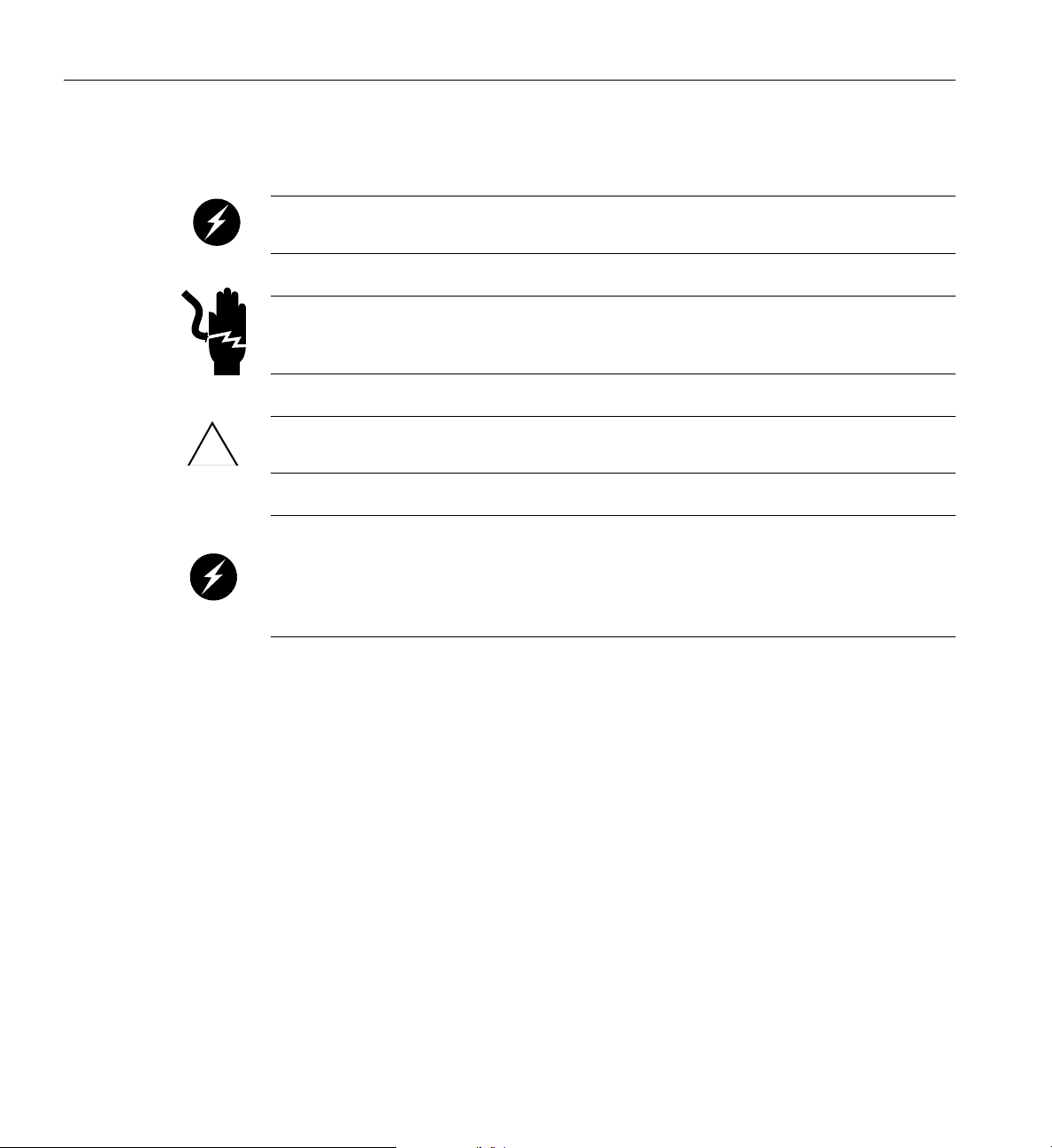
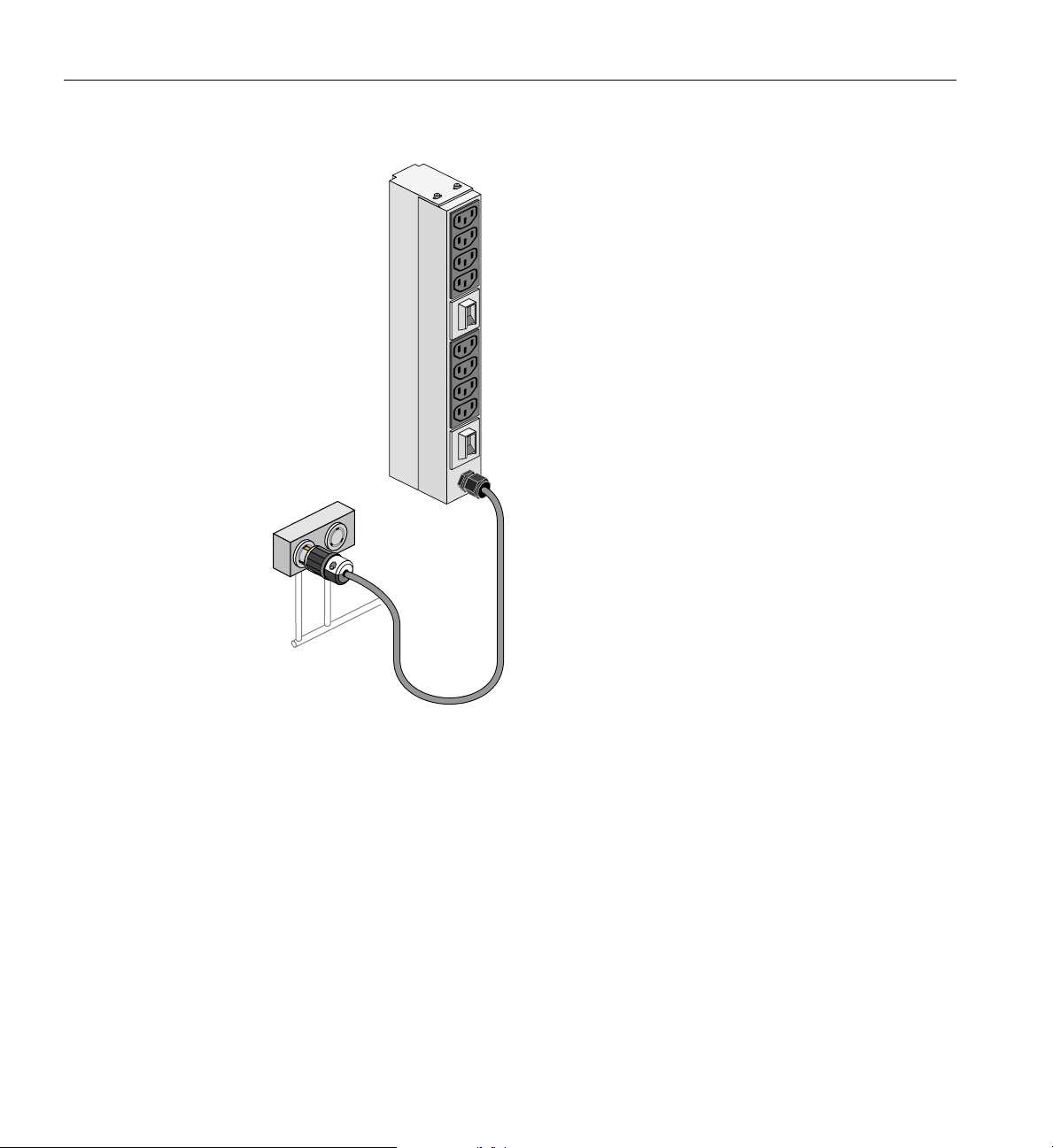
When possible, each power supply in a blade enclosure should be connected to a different PDU
within the rack. This will ensure the maximum amperage output of a single PDU is not exceeded
if a power supply fails.
Power cord
Figure 1-1 UV 3000 Blade Enclosure Power Supply and Cable Location Example
3. If you plan to power on a server that includes optional mass storage enclosures, make sure
that the power switch on the rear of each PSU/cooling module (one or two per storage
enclosure) is in the
1 (on) position.
4. Make sure that all PDU circuit breaker switches (see the examples in Figure 1-2 on page 6
and Figure 1-3 on page 7) are turned on to provide power to the server when the system is
powered on.
Preparing to Power On
To prepare to power on your system, follow these steps:
1. Check to ensure that the power connector on the cable between th
units (PDUs) and the wall power-plug receptacles are securely plugged in.
2. For each individual UV 3000 blade enclosure that you want to power on, make sure that the
power cables are plugged into all the power supplies correctly, see the example in
Figure 1-1. Setting the circuit breakers on the PDUs to the “On” position will apply power to
007-6402-001 3
e rack’s power distribution
Page 24

1: Operation Procedures
3. If you plan to power on a UV 3000 system that includes optional mass storage enclosures,
4. Make sure that all PDU circuit breaker switches are turned on to provide power to the server
SGI UV 3000 PDUs
The SGI UV 3000 systems can use different types of power distribution units (PDUs). The type
used can depend on operating location (country) and power needs. The following subsections list
optional North American and International PDU information available at the time this document
was published. Check with your SGI sales or service organization for additional information.
North America PDU Options
• Two outlet single-phase 220V PDU (C19 outlets @ 16 Amps max per outlet)
the individual UV 3000 IRUs and will start the RMC node if it is plugged into the same
PDU. Turn off the PDU breaker switch on the PDU(s) that supply voltage to the chassis or
RMC power supplies if you want to remove all power from a particular unit.
make sure that the power switch on the rear of each PSU/cooling module (one or two per
enclosure) is in the
1 (on) position.
when the system is powered on.
– NEMA L6-30 plug with 3.66 m cable (24 Amp max output per PDU)
• Eight outlet single-phase 220V PDU (IEC320 C13 outlets 15 Amp max on each)
– NEMA L6-30 plug with 3.66 m cable (24 Amp max output per PDU)
• Nine outlet three-phase 220V PDU (IEC320 C19 outlets @ 20 Amps max per outlet)
– 4-wire, delta-connected 60 Amp IEC60309 plug with 3.66 m cable
• Nine outlet three-phase 220V PDU w/monitoring (C19 outlets)
– same specifications as (9-outlet unit) above
• Eighteen outlet three-phase 480V PDU w/monitoring (three-pin Souriau outlets for North
America only)
– 60A, 277/480V, IEC60309 560P7W plug with 2.44 m cable
4 007-6402-001
Page 25

International PDU Options
• Two outlet single-phase 220V PDU (IEC320 C19 outlets A 16 Amps max per outlet)
– NEMA L6-30 plug with 3.66 m cable (24 Amp max output per PDU)
• Eight outlet single-phase 220V PDU (IEC320 C13 outlets @ 15 Amps max per outlet)
– IEC60309 plug with 3.66 m cable (32 Amp max output per PDU)
• Nine outlet three-phase 220V PDU (IEC320 19 outlets @ 20 Amps max per outlet)
– 5-wire, 415V, 32A IEC60309 plug (WYE) with 3.66 m cable (60 Amp max per PDU)
• Nine outlet three-phase 220V PDU w/monitoring (C19 outlets)
– same specifications as (9-outlet unit) above
Additional PDU Overview information
Note: SGI PDUs are designed to fit into SGI racks. The use of SGI PDUs in 3rd-party racks may
require custom mounting hardware. If SGI PDUs are not used, the installer needs to connect each
power supply to a 20-Amp certified circuit breaker with properly rated C13/C14 cordage.
Power Connections Overview
Figure 1-2 on page 6 shows an example of an eight-plug single-phase PDU that can be used in the
SGI UV 3000 rack system. This unit is primarily used to support auxiliary equipment in the rack.
007-6402-001 5
Page 26
Power
distribution
unit (PDU)
Power
source
1: Operation Procedures
Figure 1-2 Single-Phase 8-Outlet PDU Example
6 007-6402-001
Page 27
Power Connections Overview
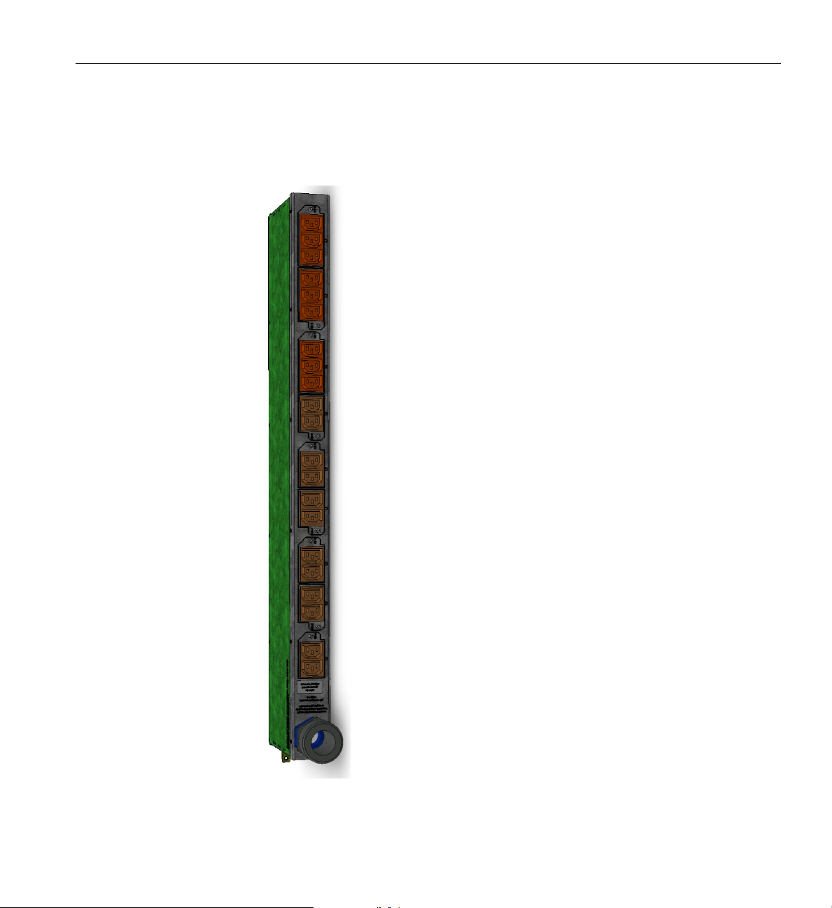
Figure 1-3 shows an example of a three-phase PDU that can be used in the SGI UV 3000 system.
These PDUs are used to distribute
power to the UV blade enclosures when the system is
configured with three-phase power.
Figure 1-3 Three-Phase PDU Example
007-6402-001 7
Page 28

1: Operation Procedures
System Connections Overview
You can monitor and interact with your SGI UV 3000 server from the following sources:
• Using the optional SGI 1U rackmount console option you can connect directly to the system
console node for basic monitoring and administration of the system. See
Admin Server Option” in Chapter 2 for more information.
• A PC or workstation on the local area network (LAN) can connect to the RMC’s external
Ethernet port and set up remote console sessions.
These console connections enable you to view the status and error messages generated by the
chassis management controllers in your SGI UV 3000 system. For example, you can monitor error
messages that warn of power or temperature values that are out of tolerance. See the section
Console Plus Admin Server Option” in Chapter 2, for additional information. The following
subsections describe the options for establishing and using communication connections to work
with your SGI UV 3000.
Connecting to the UV System Control Network
“1U Console Plus
“1U
All SGI UV 3000 systems use a rack management controller (RMC) node which communicates
with the chassis management controllers (CMCs) which in turn communicate with the blade
management controllers (BMCs). These components in concert are generically known as the
system control network. The SGI UV 3000 system control network provides control and
monitoring functionality for each chassis, blade, power supply, and fan assembly in the system.
The RMC is connected to each of the CMCs in the system via an external Ethernet cable. CMCs
are connected to the BMCs via the chassis backplane. Note that the RMC supports a maximum of
24 Ethernet ports for CMC interconnect. The CMCs and their enclosures must all be localized.
Note that the RMC does not contain a BMC or directly physically connect with any blade BMC.
The RMC/CMC network provides the following functionality:
• Powering the entire system on and off.
• Powering individual UV chassis on and off.
• Monitoring the environmental state of the system, including voltage levels.
• Monitors and controls status LEDs on the enclosure.
8 007-6402-001
Page 29
System Connections Overview
• Supports entry of controller commands to view and/or change system configuration
parameters. See the SGI UV RMC Software User Guide (P/N 007-6361-00x) for a complete
list of command line interface (CLI) commands.
• Provides access to the system OS console allow
• Provides the ability to flash system BIOS.
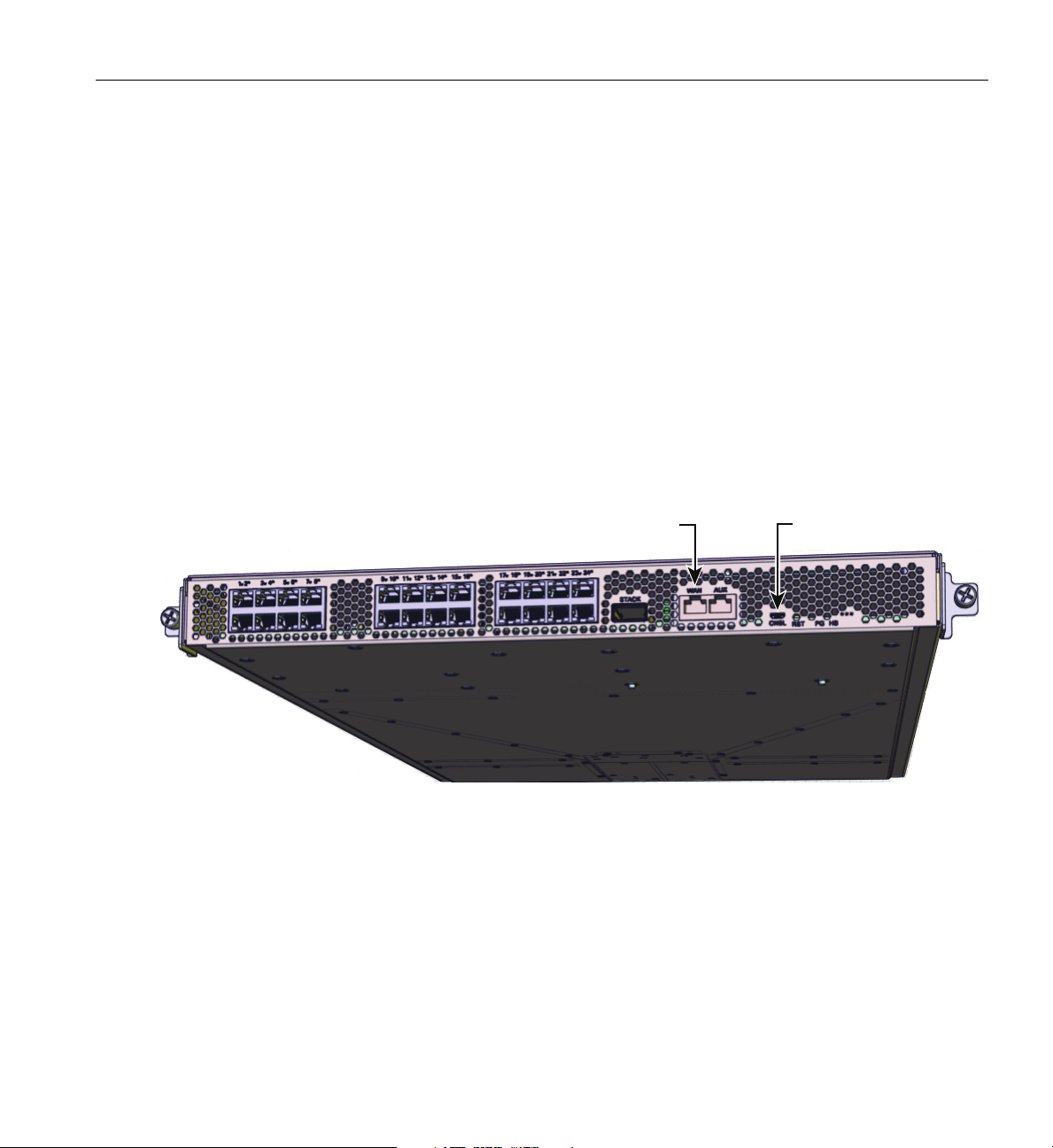
RMC System Control Access
Access to the SGI UV 3000 system controller network is accomplished by the following methods:
• A LAN connection to the RJ-45
• A USB-to-micro-USB serial connection to the
the RMC front panel example.
ing you to run diagnostics and boot the OS.
WAN port on the RMC node, (see Figure 1-4).
“Console” port (see CNSL in Figure 1-4) on
WAN LAN
connector
CNSL micro-USB
connector
Figure 1-4 SGI UV RMC Front Panel Connections Example
Once a connection to the RMC is established, the connection can be used to monitor, configure,
power on and power off the UV3000 system.
007-6402-001 9
Page 30

1: Operation Procedures
UV 3000 System Connections
Administrative commands for the SGI UV 3000 system are through the RMC interface/UV
command line interface (CLI) or through an IPMI 2.x LAN interface.
The Ethernet connection is the most common method of accessing the system console. The RMC
acts as an administrative focal-point for UV 3000 systems.
Administrators/users can perform one of the following options for connectivity:
• An in-rack or portable system console can be directly connected to the RMC micro-USB
connect port, (labeled
laptop or workstation that is physically located near the system. Note that the USB
connection requires use of a terminal emulator on the connected system.
• A LAN connection allows access to the RMC via ssh, or via an IPMI 2.x client. The RMC
supports a limited IPMI 2.x interface, basically allowing powering the system on/off from an
IPMI client. This LAN connection must be made to the RJ-45
connection can be used with a local or remote IPMI-enabled console device.
Note: The RMC firmware is not fully IPMI 2.x compliant and IPMI 2.x is not a supported
interface if the UV3000 system is partitioned.
CNSL- see Figure 1-4 on page 9). This requires connecting from a
WAN port on the RMC. The
Serial Port Connection to the RMC
Use a USB-to-micro-USB cable to administer your system locally from the RMC.
Connect the cable from your administrative laptop or other device directly to the port labeled
CNSL on the RMC, reference the location shown in Figure 1-5 on page 11. Note that the RMC
will not (by default) require a password when you login via the CNSL port.
The console type and how these console types are connected to the SGI UV 3000 systems is
determined by what console option is chosen. Establishing a serial console connection to the RMC
does require specific functional parameters which are listed in the next subsection.
10 007-6402-001
Page 31

USB-Connected Console Hardware Requirements
CNSL
WAN
2423
222120
19
18
24
23
22
21
20
19
18
17
17
1615
1413121110
16
15
14
13
12
11
10
9
9
8
7
6
5
4
3
2
8
7
6
5
4
3
2
1
1
PS HBRST
CNSL
AUXWAN
STACK
The local USB-connected terminal should be set to the following functional modes:
• Baud rate of 115,200
• 8 data bits
• One stop bit
• No parity
• No hardware flow control (RTS/CTS)
UV 3000 System Connections
Figure 1-5 RMC Ethernet LAN (WAN Port) and CNSL Location Example
Ethernet (LAN) Connection to the RMC
If you have an SGI UV 3000 system and wish to use a remote or local system to administer the
UV system via LAN, you can connect via Ethernet cable to the RMC node’s
in Figure 1-5).
If you intend to use a LAN-connected administrative server to communicate w
RMC will either need to be assigned:
• A DHCP IP address
• Or, you will need to configure it with a static IP address
See the following subsections for more information.
007-6402-001 11
WAN port (identified
ith the RMC, the
Page 32

1: Operation Procedures
Establishing RMC IP Hardware Connections
For IP address configuration, there are two options: DHCP or static IP. The following subsections
provide information on the setup and use of both.
Note: Both options require the use of the RMC’s micro-USB serial port, refer to Figure 1-4 on
page 9.
LAN Network (LAN RJ-45) connections to the SGI UV 3000 RMC are always made via the WAN
port.
For DHCP, you must determine the IP address that the RMC has been assigned; for a static IP, you
must configure the RMC to use the desired static IP address.
To use the serial port connection, you must attach and properly configure a micro-USB interface
cable to the RMC’s
Hardware Requirements” on page 11.
When the serial port session is established, the console will show an RMC login, and the user can
login to the RMC as user "root". Note that there is not (by default) a password required to access
the RMC via the
CNSL port. Configure the serial port as described in “USB-Connected Console
CNSL port.
Using DHCP to Establish an IP Address
To obtain and use a DHCP generated IP address, plug the RMC's external RJ-45 network port
(
WAN) into a network that provides IP addresses via DHCP; the RMC can then acquire an IP
address.
To determine the IP address assigned to the RMC, you must first establish a connection to the
RMC’s USB port (as indicated in the section
“USB-Connected Console Hardware Requirements”
on page 11), and run the command "ifconfig eth1". This will report the IP address that the
RMC is configured to use.
To switch from a static IP back to DHCP, the configuration file
/etc/sysconfig/ifcfg-eth1 on the RMC must be modified (see additional instructions
in the
“Using a Static IP Address” section). The file must contain the following line to enable use
of DHCP:
BOOTPROTO=dhcp
12 007-6402-001
Page 33

Using a Static IP Address
Controlling the UV 3000 System
To configure the RMC to use a static IP address, the
/etc/sysconfig/ifcfg-eth1 on the RMC must be edited.
The configuration file should be modified to contain these lines:
BOOTPROTO=dhcp
must be commented out, and the entries:
BOOTPROTO=static
IPADDR=
NETMASK=
must be uncommented and set appropriately. Obtain the appropriate values for the IPADDR and
NETMASK from your system administrator/IT organization.
GATEWAY=<network gateway IP address>
HOSTNAME=<hostname to use>
Note that the GATEWAY and HOSTNAME lines are optional.
Once the changes are made, save the file and reboot the RMC. After it reboots, it will be
configured with the specified IP address.
Controlling the UV 3000 System
The following subsections describe options for controlling the SGI UV 3000 using LAN or serial
interface methods.
UV 3000 IPMI 2.x Administration Overview
IPMI 2.x protocols can be used to monitor and/or administer a UV 3000 system remotely using
system management software available at the customer site. IPMI 2.x can provide remote access
to multiple users at different locations for networking. It also allows a user/system administrator
to monitor and manage specific computer events remotely.
007-6402-001 13
Page 34

1: Operation Procedures
Note that the IPMI interface operates independently from the operating system. IPMI 2.x
commands can be used to query inventory information, or to perform recovery procedures such as
issuing requests from a local or remote console via LAN for system power-up, power-down or
rebooting. The IPMI 2.x default username and password are ADMIN and ADMIN.
Availability of these functions will vary based on end user hardware/software options and
configurations. Check with your SGI sales or service representative for available options. See
Figure 1-5 on page 11 for an example location of the RMC’s WAN connector port.
Power On Example Using the RMC Network Connection
You can use a network connection to power on your UV 3000 system as described in the following
steps:
1. You can use the IP address of the RMC to perform an SSH login, as follows:
ssh root@<IP-ADDRESS>
Typically, the default LAN password for the RMC set out of the SGI factory is root.
The following example shows the RMC prompt:
SGI UV3000 RMC, Rev. 1.1.xx [Bootloader 1.1.x]
RMC:r001i01c>
This refers to rack 1, RMC 1.
2. Power up your UV 3000 system using the power on command, as follows:
RMC:> power on
The system will take time to fully power up (depending on size and options). Larger systems take
longer to fully power on. See the following subsections for more information on the system
command line interface and usage of commands.
The Command Line Interface
The UV command line interface is accessible by logging directly into a rack management
controller (RMC). Note that the interface is nearly identical to a CMC login.
Log in as root, (default password root) when logging into the RMC. As in this example:
asylum$ ssh root@uv3000-rmc
14 007-6402-001
Page 35

Once a connection to the RMC is established, system control commands can be entered. See the
following subsection for some examples.
See “Powering On and Off from the Command Line Interface” on page 16 for additional specific
examples of using the CLI commands.
Example CLI Commands Used
The following is a list of some available UV CLI commands:
auth authenticate SSN/APPWT change
bios perform bios actions
bmc access BMC shell
Controlling the UV 3000 System
root@uv3000-rmc's password: root
SGI UV3000 RMC, Rev. 1.1.xx [Bootloader 1.1.x]
RMC:r001i01c> help
rmc access RMC shell
config show system configuration
console access system consoles
help list available commands
hel access hardware error logs
hwcfg access hardware configuration variable
leds display system LED values
log display system controller logs
power access power control/status
Type '<cmd> --help' for help on individual commands.
007-6402-001 15
Page 36

1: Operation Procedures
Powering On and Off from the Command Line Interface
The SGI UV 3000 command line interface is accessible by logging into the RMC as root.
Information on booting Linux from the shell prompt is included at the end of the subsection
(
“Monitoring Power On Example” on page 16). The following command options may be used
with the RMC CLI:
Power On Example
usage: power [-vcow] on|up [TARGET]...turns power on
-v, --verbose verbose output
-c, --clear clear EFI variables (system and partition targets only)
-o, --override override partition check
-w, --watch watch boot progress
Power Down Example
usage: power [-vo] off |down [TARGET]...shuts power down
Reset System Example
usage: power [-vchow] reset [TARGET]...resets the system power
Power Status Check Example
usage: power [-vl0ud] status [TARGET]...checks power-on status
To monitor the power-on sequence during boot, see the next section “Monitoring Power On
Example”.
Monitoring Power On Example
Establish another connection to the RMC and use the uvcon command to open a system console
and monitor the system boot process. Use the following steps:
RMC:> uvcon
uvcon: attempting connection to localhost...
16 007-6402-001
Page 37

Controlling the UV 3000 System
uvcon: connection to RMC (localhost) established.
uvcon: requesting baseio console access at r001i01b00...
uvcon: tty mode enabled, use ’CTRL-]’ ’q’ to exit
uvcon: console access established
uvcon: RMC <--> BASEIO connection active
************************************************
******* START OF CACHED CONSOLE OUTPUT *******
************************************************
******** [20100512.143541] BMC r001i01b10: Cold Reset via NL
broadcast reset
******** [20100512.143541] BMC r001i01b07: Cold Reset via NL
broadcast reset
******** [20100512.143540] BMC r001i01b08: Cold Reset via NL
broadcast reset
******** [20100512.143540] BMC r001i01b12: Cold Reset via NL
broadcast reset
******** [20100512.143541] BMC r001i01b14: Cold Reset via NL
broadcast reset
******** [20100512.143541] BMC r001i01b04: Cold Reset via NL....
Note: Use CTRL-] q to exit the console when needed.
Depending on the size of your system, it can take 5 to 10 minutes for the UV 3000 system to boot
to the EFI shell. When the shell> prompt appears, enter fs0: as in the following example:
shell> fs0:
At the fs0: prompt, enter the Linux boot loader information, as follows:
fs0:> /efi/suse/elilo.efi
The ELILO Linux Boot loader is called and various SGI configuration scripts are run and the
SUSE Linux Enterprise Server 12 Service Pack x installation program appears.
Power off an SGI UV 3000 System
To power down the UV 3000 system, use the power off command, as follows:
RMC:> power off
==== r001i01c (PRI) ====
007-6402-001 17
Page 38

1: Operation Procedures
You can also use the power status command, to check the power status of your system
RMC:> power status
==== r001i01c (PRI) ====
on: 0, off: 16, unknown: 0, disabled: 0
18 007-6402-001
Page 39

Optional In-Rack Console Server and Flat-Panel Interface
Server control/
status panel
3.5” Disk Drives (4)
Optional In-Rack Console Server and Flat-Panel Interface
A console is defined as a connection to the RMC (via an IPMI 2.x-enabled server) that provides
access to the UV system. SGI offers a rackmounted console server and flat panel interface option
that provides localized administrative function for the system. The in-rack option is sold as a
complete hardware/software solution that installs in the SGI UV 3000 system rack or I/O rack.
A console can also be a LA
connection). Serial-over-LAN is enabled by default on the IPMI 2.x-enabled console server and
normal output through the RS-232 port is disabled. In certain limited cases, a dumb (RS-232)
terminal could be used to communicate directly with the IPMI 2.x administrative server. This
connection is typically used for service purposes or for system console access in smaller systems,
or where an external LAN connection is not used or available. Check with your service
representative if use of an RS-232 terminal is required for your system.
Optional In-Rack Console Server
For end users who require an in-rack server/console as part of their UV 3000 system, a 1U server
node is offered in combination with a rack-mounted flat-panel console.
The in-rack IPMI 2.x-enabled server (Figure 1-6) is a dual-processor serverboard based on the
Intel C612 chipset. The serverboard supports two Intel
QPI link pairs connect the two processors and the I/O hub in a network on the board.
For more information on the in-rack server option, s
C1110-GP2 System User Guide, (P/N 007-6388-00x). This guide discusses the use, maintenance
and operation of the 1U server.
N-attached personal computer, laptop or workstation (RJ45 Ethernet
Xeon E5-2600 series processors. Separate
ee the SGI Rackable C1104-GP2 and
Figure 1-6 Optional In-Rack Console Server Example (Front View)
007-6402-001 19
Page 40

1: Operation Procedures
VGA Port
Ethernet LAN Ports
IPMI LAN Port
USB Ports
COM Port
UID
Power Supplies (2)
The flat panel interface console connects at the rear of the IPMI 2.x-enabled rackmount console
server as shown in Figure 1-7.
Figure 1-7 Optional (In-Rack) Administrative Console Server Rear View Example
The flat-panel console interface option (see Figure 1-8 on page 21) has the following listed
features:
1. Sl
ide Release - Move this tab sideways to slide the console out. It locks the drawer closed
when the console is not in use and prevents it from accidentally sliding open.
2. Handle - Used to push and pull the module in and out of the rack.
3. LCD Display Controls - The LCD controls include On/Off buttons and buttons to control
the position and picture settings of the LCD display.
4. Power LED - Illuminates blue when the unit is receiving power.
20 007-6402-001
Page 41

1
2
3
4
Optional SGI Remote Services (SGI RS)
Figure 1-8 Flat Panel Rackmount Console Interface Option
Optional SGI Remote Services (SGI RS)
The optional SGI RS system automatically detects system conditions that indicate potential future
problems and then notifies the appropriate personnel. This enables you and SGI global support
teams to proactively support systems and resolve issues before they develop into actual failures.
SGI Remote Services provides a secure connection
can ensure business continuance with SGI systems management and optimization.
007-6402-001 21
to SGI Customer Support - on demand. This
Page 42

1: Operation Procedures
SGI Remote Services Primary Capabilities
• 24x7 remote monitoring and data gathering of SGI UV customer systems
• Alerts and notification on changes, failures and potential failures
• Log files immediately available
• Configuration fingerprint
• Secure file transfer
• Optional secure remote access to customer systems
SGI Remote Services Benefits
• Improved uptime and system availability
• Proactive identification of issues before they create an outage
• Increase system stability by monitoring hardware and software version compatibility
• Reduced time to resolve support cases
• Greater operational efficiency
• Less involvement of customer staff during troubleshooting
• Faster support case resolution
• Improved productivity
Proactive potential problem identification can result in higher system availability
Automated Alerts and, in some instances, Case Opening results in faster problem resolution time
and less direct involvement required by Customer Support Teams. SGI Remote Services are
available for all UV systems and also other specific SGI systems.
SGI Remote Service Operations Overview
An SGI Support Services Software Agent runs on each SGI system at your location, enabling
remote system monitoring and secure communication to SGI Support staff. Your basic hardware
and software configuration as well as system health information is captured and stored in the
Cloud.
Figure 1-9 shows an example visual overview of the monitoring and response process.
22 007-6402-001
Page 43

Optional SGI Remote Services (SGI RS)
Cloud intelligence automatically reviews select Event Logs around the clock (every five minutes)
to identify potential failure information. If the Cloud intelligence detects a critical Event, it
notifies SGI support personnel.
This monitoring requires no changes to customer systems
or firewalls as long as the SGI Agent
can send HTTPS messages to highly secure Cloud and Global Access Servers. It will also have no
impact on customer network or system performance. All communication between SGI global
support and customer systems is kept secure using Secure Socket Layer (SSL) encryption. All
communication with SGI is initiated from the customer site using HTTPS protocol on port 443.
Figure 1-9 SGI Remote Services Process Overview
007-6402-001 23
Page 44

1: Operation Procedures
Optional Components
Besides adding a network-connected system console and basic VGA monitor, you can also order
the following types of hardware options on your SGI UV 3000 series server:
• Peripheral component interface (PCIe) cards in an optional PCIe expansion chassis.
• PCIe cards in a blade-mounted PCIe riser card.
• Disk drives in your dual disk drive riser card equipped compute blade.
PCIe Cards
The PCIe based I/O sub-systems, are industry standard for connecting peripherals, storage, and
graphics to a processor blade. The following are the primary configurable I/O system interfaces
for the SGI UV 3000 series systems:
• The optional full -height two-slot internal PCIe blade is a dual-node compute blade that
supports one full-height x16 PCIe Gen3 card in the top slot and one low-profile x16 PCIe
Gen3 card in the lower slot. See
• The optional dual low-profile PCIe blade supports two PCIe x16 Gen3 cards. See
Figure 1-11 on page 25 for an example.
Figure 1-10 on page 25 for an example.
• An optional external PCIe I/O expansion chassis supports up to four PCIe cards. The
external PCIe chassis is supported by connection to a compute blade using an optional host
interface card (HIC). Each x16 PCIe enabled blade host interface connector can support one
I/O expansion chassis.
Important: PCIe cards installed in an optional two-slot PCIe blade are not hot swappable or hot
pluggable. The compute blade using the PCIe riser must be powered down and removed from the
system before installation or removal of a PCIe card(s).
Not all blades or PCIe cards may be available with your system configuration. Check with your
SGI sales or service representative for availability.
24 007-6402-001
Page 45

Figure 1-10 PCIe Option Blade Example with Full-Height and Low-Profile Slots
Optional Components
Figure 1-11 PCIe Option Blade Example with Two Low-Profile Slots
007-6402-001 25
Page 46

1: Operation Procedures
PCIe Drive Controllers in BaseIO Blade
The SGI UV 3000 system offers an optional RAID or non-RAID (JBOD) PCIe-based drive
controller that resides in the BaseIO blade’s PCIe slot. Figure 1-12 shows an example of the
system disk HBA controller location in the BaseIO
blade.
Optional SAS connectors
SERIAL
PCIE
N MLK
RAID PCIe Disk Controller
VGA
SSD1
SSD0
LAN0
USB1
USB0
LAN1
USB3
USB2
BMC
Figure 1-12 BaseIO Blade and PCIe Disk Controller Example
At the time this document was published, the optional RAID controller used in the BaseIO blade
PCIe slot is an LSI MegaRAID SAS 9280-8e. This PCIe 2.0 card uses two external SAS control
connectors and supports the following:
• RAID levels 0, 1, 5, 6, and 10
• Advanced array configuration and management utilities
• Support for global hot spares and dedicated hot spares
• Support for user-defined stripe sizes: 8, 16, 32, 64, 128, 256, 512, or 1024 KB
26 007-6402-001
Page 47

The RAID controller also supports the following advanced array configuration and management
capabilities:
• Online capacity expansion to add space to an existing drive or a new drive
• No reboot necessary after expansion
• Online RAID level migration, including drive migration, roaming and load balancing
• Media scan
• User-specified rebuild rates (specifying the percentage of system resources to use from 0
• Nonvolatile random access memory (NVRAM) of 32 KB for storing RAID system
Non-RAID PCIe Disk Controller
At publication time, the LSI 9200-8e low-profile PCIe drive controller HBA is the default
non-RAID system disk controller for the SGI UV 3000. This drive controller has the following
features:
Optional Components
percent to 100 percent)
configuration information; the MegaRAID SAS firmware is stored in flash ROM for easy
upgrade.
• Supports SATA and SAS link rates of 1.5 Gb/s, 3.0 Gb/s, and 6.0 Gb/s
• Provides two x4 external mini-SAS connectors (SFF-8088)
• The HBA has onboard Flash memory for the firmware and BIOS
• The HBA is a 6.6-in. x 2.713-in., low-profile board
• Supports eight-lane, full-duplex PCIe 2.0 performance
• The HBA has multiple status and activity LEDs and a diagnostic UART port
• A x8 PCIe slot is required for the HBA to operate within the system
007-6402-001 27
Page 48

Page 49

Chapter 2
2. System Control
This chapter describes the general interaction and functions of the overall SGI UV 3000 system
control. System control parameters depend somewhat on the overall size and complexity of the
SGI UV 3000 but will generally include the following:
• The administrative LAN-to-RMC server (IPMI 2.x-enabled) and connects to the RMC’s
(
WAN) RJ-45 Ethernet port
• The rack management controller (RMC) node - (one in each UV 3000 system)
• The individual chassis-based board management controllers (BMCs) - report to the RMC
• A chassis management controller (CMC) board resides in each IRU. The CMC supports
powering up and down of the compute blades and environmental monitoring of the IRU.
Note: SGI offers a rack-mounted flat panel console option that attaches to a rack-mounted
administrative server node’s video, keyboard and mouse connectors. These two hardware options
each require 1U of space within the rack (2U total). This combination acts as an “in-rack”
console/server option for users who want localized system administration.
Levels of System Control
The system control network configuration of your server will depend on the size of the system and
control options selected. Typically, an Ethernet LAN connection to the RMC system controller
network is used. This Ethernet connection is made from a local or remote IPMI-enabled
PC/workstation which acts as a gateway and buffer between the internal UV system control
network and any other public or private local area networks.
Important: The SGI UV system control network is a private, closed network. It should not be
reconfigured in any way to change it from the standard SGI UV factory installation. It should not
be directly connected to any other network. The UV system control network is not designed for
and does not accommodate additional network traffic, routing, address naming (other than its own
007-6402-001 29
Page 50

2: System Control
schema), or DCHP controls (other than its own configuration). The UV system control network
also is not security hardened, nor is it tolerant of heavy network traffic, and is vulnerable to Denial
of Service attacks.
RMC and System Management Overview
The RMC is a separate stand-alone 1U controller installed in the SGI UV 3000 system rack. The
RMC acts as a gateway and buffer between the UV system control network and any other public
or private local area networks or administrative systems used to communicate with and control the
UV 3000. An Ethernet connection directly from the RMC to a local private or public Ethernet
allows the system to be administered directly from a local or remote console system.
shows a front-view example of the RMC unit.
The system controller network is designed into all IRUs. Controllers within the system report and
share status information via the CMC Ethernet interconnects. This maintains controller
configuration and topology information between all controllers in an SSI.
shows an example system control network using an optional and separate (remote) workstation to
monitor SGI UV 3000 systems. It is also possible to connect an optional PC or (in-rack) console
(see
Figure 2-4 on page 36) directly to the RMC.
Figure 2-1
Figure 2-2 on page 32
Note: Mass storage option enclosures are not specifically monitored by the system controller
network. Most optional mass storage enclosures have their own internal microcontrollers for
monitoring and controlling all elements of the disk array. See the user’s guide for your mass
storage option for more information on this topic.
For information on software commands used for administering network connected SGI UV 3000
systems using the SGI RMC node, see the SGI RMC Software User’s Guide (P/N 007-6361-00x).
For information on administering network connected SGI systems using the SGI Management
Center, see the SGI Management Center Administration Guide for Clusters, (P/N 007-6358-00x).
30 007-6402-001
Page 51

WAN LAN
connector
CNSL micro-USB
connector
CMC Overview
Levels of System Control
Figure 2-1 RMC Node Front Panel Example
The CMC system for the SGI UV 3000 servers manages power control and sequencing, provides
environmental control and monitoring, initiates system resets, stores identification and
configuration information, and provides console/diagnostic and scan interface. A CMC port from
each chassis management controller connects to a dedicated Ethernet switch that provides a
synchronous clock signal to all the CMCs in an SSI.
Viewing the system from the rear,
the CMC blade is on the right side of the IRU. The CMC accepts
direction from the RMC and supports powering-up and powering-down individual or groups of
compute blades and environmental monitoring of all units within its IRU. The CMC sends
operational requests to the Baseboard Management Controller (BMC) on each compute blade
installed. The CMC provides data collected from the compute nodes within the IRU to the system
RMC node upon request.
CMCs can communicate with the blade B
under a single system image (SSI); also called a partition. Each CMC shares its information with
the RMC as well as other CMCs within the SSI. Note that the RMC node, optional mass storage
MCs and other IRU CMCs when they are linked together
units and any PCIe expansion enclosures do not have a CMC installed.
007-6402-001 31
Page 52

Remote
workstation
monitor
Local Area Network (LAN)
Local Area Network (LAN)
Cat-5 Ethernet
SGI UV 3000 system rack
2: System Control
Figure 2-2 SGI UV 3000 LAN-attached Remote System Control Example
BMC Overview
Each compute blade in an IRU has a baseboard management controller (BMC). The BMC is a
built-in specialized microcontroller hardware component that monitors and reports on the
32 007-6402-001
Page 53

functional “health” status of the blade. The BMC provides a key functional element in the overall
Intelligent Platform Management Interface (IPMI) architecture.
The BMC acts as an interface to the higher levels of system control such as the IRU’s CMC board
and the higher level control system used in the RMC and administration node. The BMC can
report any on-board sensor information that it has regarding temperatures, power status, operating
system condition and other functional parameters that may be reported by the blade. When any of
the preset limits fall out of bounds, the information will be reported by the BMC and an
administrator can take some corrective action. This could entail a node shutdown, reset (NMI) or
power cycling of the individual blade.
The individual blade BMCs do not have information on the status of other blades within the IRU.
This function is handled by the CMCs via the RMC and the administrative node. Note that blades
equipped with an optional BaseIO riser board have a dedicated BMC Ethernet port.
System Controller Interaction
In all SGI UV 3000 servers all the system controller types (RMCs, CMCs and BMCs)
communicate with each other in the following ways:
System Controller Interaction
• System control commands and communications are passed between the RMC and CMCs via
a private dedicated Gigabit Ethernet network. The CMCs communicate directly with the
BMC in each installed blade by way of the IRU’s internal backplane.
• All CMCs can communicate with each other via an Ethernet “ring” configuration network
established within an SSI.
• In larger configurations the system control communication path may include a private,
dedicated Ethernet switch that allows communication between an RMC and multiple SSI
environments.
007-6402-001 33
Page 54

2: System Control
IRU Controllers
All IRUs have a chassis management controller (CMC) board installed. The following subsection
describes the basic features of the controllers:
Note: For additional information on controller commands, see the SGI UV CMC Software User
Guide (P/N 007-5636-00x).
Chassis Management Controller Functions
The following list summarizes the control and monitoring functions that the CMC performs. Many
of the controller functions are common across all IRUs, however, some functions are specific to
the type of enclosure.
• Monitors individual blade status via blade BMCs
• Controls and monitors IRU fan speeds
• Reads system identification (ID) PROMs
• Monitors voltage levels and reports failures
• Monitors and controls warning LEDs
• Monitors the On/Off power process
• Provides the ability to create multiple system partitions
• Provides the ability to flash system BIOS
1U Console Plus Admin Server Option
The SGI optional 1U console (Figure 2-3 on page 35) is a rackmountable unit that includes a
built-in keyboard/touchpad. It uses a 17-inch (43-cm) LCD flat panel display of up to 1280 x 1024
pixels. The 1U console works in concert with a 1U server (see
an “in-rack” local administrative system directly attached to the RMC.
34 007-6402-001
Figure 2-4 on page 36) to provide
Page 55

1
2
3
4
IRU Controllers
Figure 2-3 Optional 1U Rackmount Console
Flat Panel Rackmount Console Option Features
The 1U flat panel console option has the following listed features:
1. Sl
ide Release - Move this tab sideways to slide the console out. It locks the drawer closed
when the console is not in use and prevents it from accidentally sliding open.
2. Handle - Used to push and pull the module in and out of the rack.
3. LCD Display Controls - The LCD controls include On/Off buttons and buttons to control
the position and picture settings of the LCD display.
007-6402-001 35
Page 56

2: System Control
4. Power LED - Illuminates blue when the unit is receiving power.
The 1U console attaches to the system administration server using USB and HD15M connectors
or through an optional KVM switch. See Figure 2-4 for the video connection points. The 1U
console is basically a “dumb” VGA terminal, it cannot be used as a workstation or
loaded with
any system administration program.
The 27-pound (12.27-kg) console automatically goes into sleep mode when the cover is closed.
USB Ports
Ethernet LAN Ports
IPMI LAN Port
Power Supplies (2)
COM Port
UID
Figure 2-4 Optional (In-Rack) 1U System Administration Node Rear View
VGA Port
36 007-6402-001
Page 57

Chapter 3
3. System Overview
This chapter provides an overview of the physical and architectural aspects of your SGI UV 3000
series system. The major components of the SGI UV 3000 series systems are described and
illustrated.
The SGI UV 3000 series is a family of cache-coherent Non-Uniform Memory Access (ccNUMA),
computer systems that can scale from 2 to 128 Intel-based compute blades as a cache-coherent
single system image (SSI). At time of publication all SGI UV 3000 system blades are based on
Intel Xeon E5-4600 v3 processors. Future releases may scale to larger blade or processor counts
for single system image (SSI) applications. Contact your SGI sales or service representative for
the most current information on these topics.
In a ccNUMA system, each processor board (node) contains memory that it shares with the other
processors in the system. Because the system is modular, it combines the advantages of lower
entry-level cost with global scalability in processors, memory, and I/O. You can install and operate
the SGI UV 3000 series system in your lab or server room. Each 42U SGI rack holds one to four
10-U high enclosures that support up to eight compute/memory and I/O sub modules known as
“blades.” These blades contain printed circuit boards (PCBs) with ASICS, processors, memory
components and I/O chipsets mounted on a mechanical carrier. The blades slide directly in and out
of the SGI UV 3000 IRU enclosures.
This chapter consists of the following sections:
• “System Models” on page 39
• “System Architecture” on page 41
• “System Features” on page 43
• “System Components” on page 48
Figure 3-1 shows the front view of a single-rack SGI UV 3000 system.
007-6402-001 37
Page 58

SGI UV 3000
3: System Overview
Figure 3-1 SGI UV 3000 D-Rack System and Front Lock Example
38 007-6402-001
Page 59

System Models
System Models
The basic enclosure within the SGI UV 3000 system is the 10U high “individual rack unit” (IRU).
The IRU enclosure contains up to eight compute blades connected to each other via a backplane.
Each IRU has ports that are brought out to external NUMAlink 6 connectors. The 42U rack for
this server houses all IRU enclosures, option modules, and other components; up to 64 processor
sockets in a single rack. The SGI UV 3000 server system requires a minimum of one BaseIO
equipped blade for every 128 system blades. Higher blade or socket counts supported in an SSI
may be available in future releases, check with your SGI sales or service representative for the
most current information.
Note: Systems operated without an optional administration node must have an optional external
DVD drive available to connect to the BaseIO blade.
Figure 3-2 shows an example of how IRU placement is done in a single-rack SGI UV 3000 server.
The system requires a minimum of one 42U tall rack with three single-phase power distribution
unit (PDU) plugs per IRU installed in the rack. Three outlets are required to support each power
shelf. There are three power supplies per power shelf and two power connections are required for
an optional 1U system administration node and one for an optional 1U terminal.
You can also add additional PCIe expansion enclosures or RAID and non-RAID disk storage to
your server system. Power outlet needs for these options should be calculated in advance of
determining the number of outlets needed for the overall system.
007-6402-001 39
Page 60

Individual Rack Unit (IRU)
Optional 1U administration node
Optional 1U administration console
UV Rack
IRU
IRU
IRU
IRU
3: System Overview
40 007-6402-001
Figure 3-2 SGI UV 3000 IRU and Rack Example
Page 61

System Architecture
The SGI UV 3000 computer system is based on a cache-coherent Non-Uniform Memory Access
(ccNUMA) shared memory architecture. The system uses a global-address-space, cache-coherent
multiprocessor that scales up to 128 blades in a single-system image. Because it is modular, the
UV 3000 system combines the advantages of lower entry cost with the ability to scale processor
count, memory, and I/O independently in each rack. Note that larger SSI configurations may be
offered in the future, contact your SGI sales or service representative for additional information.
The system architecture for the SGI UV 3000 system is a sixth-generation NUMAlink
shared-memory architecture known as NUMAlink 6 or NL6. In the NUMAlink 6 architecture, all
processors and memory can be tied together into a single logical system. This combination of
processors, memory, and internal switches constitute the interconnect fabric called NUMAlink
within and between each 10U IRU enclosure.
The basic expansion building block for the NUMAlink interconnect is the processor node; each
processor node consists of a dual-Hub ASIC (also known as a HARP) and two multi-core
processors with on-chip secondary caches. The Intel processors are connected to the dual-Hub
ASICs via quick path interconnects (QPIs). Each dual-HUB ASIC is also connected to the
system’s NUMAlink interconnect fabric through one of sixteen NL6 ports.
System Architecture
The dual-Hub ASIC is the heart of the processor and memory node blade technology. This
specialized ASIC acts as a crossbar between the processors and the network interface. The Hub
ASIC enables any processor in the SSI to access the memory of all processors in the SSI.
Figure 3-3 on page 42 shows a functional block diagram of the SGI UV 3000 series system IRU.
System configurations of up to eight IRUs can be constructed without the use of external routers.
Routerless systems can have any number of blades up to a maximum of 64. Routerless system
topologies reduce the number of external NUMAlink cables required to interconnect a system.
External optional routers are needed to support multi-rack systems with more than four IRUs, see
Chapter 5, “Optional Octal Router Chassis Information” for more information.
007-6402-001 41
Page 62

N
I
2
-
3
N
I
2
-
3
N
I
0
-3
N
I
0
-
3
N
I
2
-
3
N
I
2
-
3
N
I
0
-
3
N
I
0
-
3
N
I
2
-
3
N
I
2
-
3
N
I
0
-
3
N
I
0
-
3
N
I
2
-
3
N
I
2
-
3
N
I
0
-
3
N
I
0
-
3
N
I
1
1
N
I
1
3
N
I
3
1
N
I
3
3
N
I
1
3
N
I
1
1
N
I
3
3
N
I
3
1
N
I
1
1
N
I
1
3
N
I
3
1
N
I
3
3
N
I
1
3
N
I
1
1
N
I
3
3
N
I
3
1
N
I
0-2
0
3
N
I
2-2
NI
2-2
NI
2-2
-
N
I
0
-
2
NI
0-2
N
I
0
2
N
I
2
2
1
2
N
I
1
1
N
I
1
3
N
I
3
1
N
I
3
3
N
I
1
3
N
I
1
1
N
I
3
3
N
I
3
1
N
I
1
1
N
I
1
3
N
I
3
1
N
I
3
3
N
I
1
3
N
I
1
1
N
I
3
3
N
I
3
1
N
I2
-
2
4
7
N
I0
-
2
N
I0
-
2
N
I
2
2
N
I
0
-
2
N
I2
-
2
N
I
0
-2
N
I
2
-2
5
6
N
I
3-0
N
I
3
-
0
N
I
3-0
N
I
3-0
N
I
3-0
N
I
3-0
N
I
3
-
0
N
I
3
-
0
N
I
1-0
N
I
1
-
0
N
I
1-0
N
I
1-0
N
I
1
-
0
N
I
1
-
0
N
I
1-0
N
I
1
-
0
N
I
1
-
2
N
I
1
-
2
N
I
1
-
2
N
I
1
-2
N
I
3
-2
N
I
3
-
2
N
I
3
-
2
N
I
3
-
2
N
I
3
2
N
I
1
2
N
I
3
-
2
N
I
1
-
2
N
I
3
-
2
NI3-2
N
I
1
2
N
I
1
-
2
IRU Backplane Connections
Left
Backplane
Right
Backplane
Note: this drawing only shows the cabling
between the compute blades within the
IRU. External cabling (cabling that exits
the IRU) is not shown.
3: System Overview
Figure 3-3 Functional Block Diagram of the Individual Rack Unit (IRU)
42 007-6402-001
Page 63

System Features
The main features of the SGI UV 3000 series server systems are discussed in the following
sections:
• “Modularity and Scalability” on page 43
• “Distributed Shared Memory (DSM)” on page 43
• “Chassis Management Controller (CMC)” on page 45
• “Distributed Shared I/O” on page 45
• “Reliability, Availability, and Serviceability (RAS)” on page 46
Modularity and Scalability
The SGI UV 3000 series systems are modular systems. The components are primarily housed in
building blocks referred to as individual rack units (IRUs). Additional optional mass storage may
be added to the rack along with additional IRUs. You can add different types of blade options to
a system IRU to achieve the desired system configuration. You can easily configure systems
around processing capability, I/O capability, memory size, MIC/GPU capability or storage
capacity. The air-cooled IRU enclosure system has redundant, hot-swap fans and redundant,
hot-swap power supplies.
System Features
Distributed Shared Memory (DSM)
In the SGI UV 3000 series server, memory is physically distributed both within and among the
IRU enclosures (compute/memory/I/O blades); however, it is accessible to and shared by all
NUMAlinked devices within the single-system image (SSI). This is to say that all NUMAlinked
components sharing a single Linux operating system, operate and share the memory “fabric” of
the system. Memory latency is the amount of time required for a processor to retrieve data from
memory. Memory latency is lowest when a processor accesses local memory. Note the following
sub-types of memory within a system:
• If a processor accesses memory that is directly connected to its resident socket, the memory
is referred to as local memory.
the blade’s memory, compute and I/O pathways.
• If a processor needs to access memory located in another socket, or on another blade within
the IRU, (or other NUMAlinked IRUs) the memory is referred to as remote memory.
007-6402-001 43
Figure 3-4 on page 44 shows a conceptual block diagram of
Page 64

3: System Overview
• The total memory within the NUMAlinked system is referred to as global memory.
Figure 3-4 SGI UV 3000 Blade Nodes Block Diagram Example
44 007-6402-001
Page 65

Distributed Shared I/O
Like DSM, I/O devices are distributed among the blade nodes within the IRUs. Each BaseIO riser
card equipped blade node is accessible by all compute nodes within the SSI (partition) through the
NUMAlink interconnect fabric.
Chassis Management Controller (CMC)
Each IRU has a chassis management controller (CMC) located directly below the cooling fans in
the rear of the IRU. The chassis manager supports powering up and down of the compute blades
and environmental monitoring of all units within the IRU.
One GigE port from each compute blade connects to the CMC blade via the internal IRU
backplane. A second GigE port from each blade slot is also connected to the CMC. This
connection is used to support a BaseIO riser card. Only one BaseIO is supported in an SSI. The
BaseIO must be the first blade (lowest) in the SSI.
ccNUMA Architecture
System Features
As the name implies, the cache-coherent non-uniform memory access (ccNUMA) architecture has
two parts, cache coherency and nonuniform memory access, which are discussed in the sections
that follow.
Cache Coherency
The SGI UV 3000 server series use caches to reduce memory latency. Although data exists in local
or remote memory, copies of the data can exist in various processor caches throughout the system.
Cache coherency keeps the cached copies consistent.
To keep the copies consistent, the ccNUMA architecture uses directory-based coherence protocol.
In directory-based coherence protocol, each block of memory (128 bytes) has an entry in a table
that is referred to as a directory. Like the blocks of memory that they represent, the directories are
distributed among the compute/memory blade nodes. A block of memory is also referred to as a
cache line.
Each directory entry indicates the state of the memory block that it represents. For example, when
the block is not cached, it is in an unowned state. When only one processor has a copy of the
007-6402-001 45
Page 66

3: System Overview
memory block, it is in an exclusive state. And when more than one processor has a copy of the
block, it is in a shared state; a bit vector indicates which caches may contain a copy.
When a processor modifies a block of data, the processors that have the same block of data in their
caches must be notified of the modification. The SGI UV 3000 server series uses an invalidation
method to maintain cache coherence. The invalidation method purges all unmodified copies of the
block of data, and the processor that wants to modify the block receives exclusive ownership of
the block.
Non-uniform Memory Access (NUMA)
In DSM systems, memory is physically located at various distances from the processors. As a
result, memory access times (latencies) are different or “non-uniform.” For example, it takes less
time for a processor blade to reference its locally installed memory than to reference remote
memory.
Reliability, Availability, and Serviceability (RAS)
The SGI UV 3000 server series components have the following features to increase the reliability,
availability, and serviceability (RAS) of the systems.
• Power and cooling:
– IRU power supplies are redundant and can be hot-swapped under most circumstances.
Note that this might not be possible in a “fully loaded” system. If all the blade positions
are filled, be sure to consult with a service technician before removing a power supply
while the system is running.
– IRUs have overcurrent protection at the blade and power supply level.
– Fans are redundant and can be hot-swapped.
– Fans run at multiple speeds in the IRUs. Speed increases automatically when
temperature increases or when a single fan fails.
• System monitoring:
– System controllers monitor the internal power and temperature of the IRUs, and can
automatically shut down an enclosure to prevent overheating.
– All main memory has Intel Single Device Data Correction, to detect and correct 8
contiguous bits failing in a memory device. Additionally, the main memory can detect
and correct any two-bit errors coming from two memory devices (8 bits or more apart).
46 007-6402-001
Page 67

System Features
– All high speed links including Intel Quick Path Interconnect (QPI), Intel Scalable
Memory Interconnect (SMI), and PCIe have CRC check and retry.
– The NUMAlink interconnect network is protected by cyclic redundancy check (CRC).
– Each blade/node installed has status LEDs that indicate the blade’s operational
condition; LEDs are readable at the front of the IRU.
– Systems support the optional SGI Remote Services (SGI RS), a tool that monitors the
system; when a condition occurs that may cause a failure, the remote services software
agent notifies the appropriate SGI personnel.
– Systems support remote console and maintenance activities.
• Power-on and boot:
– Automatic testing occurs after you power on the system. (These power-on self-tests or
POSTs are also referred to as power-on diagnostics or PODs).
– Processors and memory are automatically de-allocated when a self-test failure occurs.
– Boot times are minimized.
• Further RAS features:
– All system faults are logged in files.
– Memory can be scrubbed using error checking code (ECC) when a single-bit error
occurs.
007-6402-001 47
Page 68

3: System Overview
System Components
The SGI UV 3000 series system features the following major components:
• 24U or 42U rack. These racks are used for both compute and I/O racks in the SGI UV 3000
• Individual Rack Unit (IRU). This enclosure contains three power supplies, 2-8
• Compute blade. Holds two processor sockets and 8 or 16 memory DIMMs. Each compute
• BaseIO enabled compute blade. I/O riser enabled blade that supports all base system I/O
system. Up to four IRUs can be installed in each 42U rack. There is also space for an RMC
or optional administrative node and other optional 19-inch rackmounted components.
compute/memory blades, BaseIO and other optional riser enabled blades for the SGI UV
3000. The enclosure is 10U high.
system components.
blade can be ordered with a riser card that enables the blade to support various I/O options.
functions including two Ethernet connectors, one BMC Ethernet port and three USB ports.
System disks can be controlled by a PCIe disk controller installed in the BaseIO blade’s
PCIe slot.
Note: While the BaseIO blade is capable of RAID 0 support, SGI does not recommend the
end user configure it in this way. RAID 0 offers no fault tolerance to the system disks, and a
decrease in overall system reliability. The SGI UV 3000 ships with RAID 1 functionality
(disk mirroring) configured if the option is ordered.
Figure 3-6 on page 50 shows a front-view example of the BaseIO blade.
Figure 3-5 on page 49 shows the SGI UV 3000 IRU
• Dual disk enabled compute blade. This riser enabled blade supports two hard disk drives
that normally act as the system disks for the SSI. This blade must be installed adjacent to and
physically connected with the BaseIO enabled compute blade. JBOD, RAID 0 and RAID 1
are supported. Note that you must have the BaseIO riser blade optionally enabled to use
RAID 1 mirroring on your system disk pair.
• Two-Slot Internal PCIe enabled compute blade. The internal PCIe riser based compute
blade supports two internally installed PCI Express option cards. Either two half-height or
one half-height and one full-height cards are supported.
• MIC/GPU PCIe enabled compute blade. This blade supports one optional MIC or GPU
card in the upper slot via PCIe interface to the bottom node board. Option cards are limited,
check with your SGI sales or service representative for available types supported.
• External PCIe enabled compute blade. This PCIe enabled board is used in conjunction
with an external PCIe expansion enclosure. A x16 adapter card connects from the blade to
the external PCIe expansion enclosure.
48 007-6402-001
Page 69

System Components
Note: PCIe card options may be limited, check with your SGI sales or support representative.
Compute
blade 3
Compute
blade 2
Compute
blade 1
Compute
blade 0
Compute
blade 7
Compute
blade 6
Compute
blade 5
SERIAL
PCIE
VGA
SSD1
SSD0
LAN0
LAN1
BMC
USB1
USB3
USB0
USB2
Compute
blade 4
PS0 PS2PS1
Figure 3-5 SGI UV 3000 IRU System Components Example
007-6402-001 49
Page 70

3: System Overview
USB1
USB0
LAN1
LAN0
BMC
PCIE
Optional SAS connectors
VGA
SERIAL
USB3
USB2
SSD1
SSD0
N MLK
Optional BaseIO SSDs
The BaseIO blade can be configured with one or two internal 1.8-inch solid state drives (SSDs).
These drives are located in the lower-left section of the BaseIO blade, as seen in Figure 3-6.
The SSDs can be configured as JBOD or RAID1. The RAID1 SSD
pair is a software RAID1 and
two SSDs must be ordered with the system BaseIO to enable this configuration.
Figure 3-6 BaseIO Riser Enabled Blade Front Panel Example
50 007-6402-001
Page 71

MIC/GPU Enabled Compute Blade
The single-socket MIC/GPU enabled compute blade has one single socket node blade and
supports one PCIe accelerator card. The MIC/GPU enabled compute blade has the following
features:
• One HARP ASIC based board assembly with twelve NUMALink six (NL6) ports that
connect the blade
QSFP ports.
• Specialized connectors support the connection to both the bottom compute node and the top
or GPU board assembly.
MIC
• One Bottom compute node board assembly with a single processor socket also supports
eight memory DIMM slots.
• One baseboard management controller (BMC) and one x16 Gen3 PCIe full-height
double-wide
System Components
to the backplane and four NL6 ports connecting the blade to external
slot that supports a single MIC or GPU accelerator card.
• The accelerator card connects directly
to the bottom compute board assembly via a ribbon
cable and draws power from the IRU backplane.
Figure 3-7 MIC/GPU Enabled Compute Blade Example Front View
007-6402-001 51
Page 72

3: System Overview
Bay (Unit) Numbering
Bays in the racks are numbered using standard units. A standard unit (SU) or unit (U) is equal to
1.75 inches (4.445 cm). Because IRUs occupy multiple standard units, IRU locations within a rack
are identified by the bottom unit (U) in which the IRU resides. For example, in a rack, an IRU
positioned in U01 through U10 is identified as U01.
Rack Numbering
Each rack is numbered with a three-digit number sequentially beginning with 001. A rack contains
IRU enclosures, optional mass storage enclosures, and potentially other options. In a single
compute rack system, the rack number is always 001.
Optional System Components
Availability of optional components for the SGI UV 3000 systems may vary based on new product
introductions or end-of-life components. Some options are listed in this manual, others may be
introduced after this document goes to production status. Check with your SGI sales or support
representative for current information on available product options not discussed in this manual.
52 007-6402-001
Page 73

Overview
Chapter 4
4. Rack Information
This chapter describes the physical characteristics of the tall (42U) and short (24U) SGI UV 3000
racks in the following sections:
• “Overview” on page 53
• “SGI UV 3000 Series Rack (42U)” on page 54
• “SGI UV 3000 42U System Rack Technical Specifications” on page 58
• “The 24U (Short) Rack” on page 59
At the time this document was published only the tall (42U) SGI UV 3000 rack (shown in
Figure 4-2) and the optional 24U (short rack) are available from the SGI factory for use with SGI
UV systems. Other racks may be available to house the system IRUs, RMC, optional servers,
storage and console equipment, check with your SGI sales or service representative for more
information.
007-6402-001 53
Page 74

4: Rack Information
SGI UV 3000 Series Rack (42U)
The tall rack (shown in Figure 4-1 on page 55) has the following features and components:
• Front and rear door. The front door is opened by grasping the outer end of the
rectangular-shaped door piece and pulling outward. It uses a key lock for security purposes
that should open all the front doors in a multi-rack system (see
Note: The front door and rear door locks are keyed differently. The rear lock on an air-cooled
rack is shown in Figure 4-1 on page 55. The optional water-chilled rear door (see Figure 4-3
on page 57) does not use a lock.
The standard rear door has a push-button key lock to prevent unauthorized access to the
system. The rear doors have a master key that locks and unlocks all rear doors in a system
made up of multiple racks. You cannot use the rear door key to secure the front door lock.
• Cable entry/exit area. Cable access openings are located in the front floor and top of the
rack. Multiple cables are attached to the front of the IRUs; therefore, a significant part of the
cable management occurs in the front part of the rack. The stand-alone optional system
administration node, system console and any optional storage modules installed in the same
rack with the IRU(s) use rear cable management. Optional inter-rack communication cables
can pass through the top of the rack. These are necessary whenever the system consists of
multiple racks. I/O and power cables normally pass through the bottom of the rack.
Figure 4-2 on page 56).
• Rack structural features. The rack is mounted on four casters; the two rear casters swivel.
There are four leveling pads available at the base of the rack. The base of the rack also has
attachment points to support an optional ground strap, and/or seismic tie-downs.
• Power distribution units in the rack. Up to 15 outlets may be required for a single-rack
IRU system as follows:
– Allow three outlets for the first IRU
– Two outlets for an optional administration node (server)
– One outlet for an optional administration console
– Two outlets for each storage or PCIe expansion chassis
– Allow three more outlets for each additional IRU in the system
Note than an eight outlet single-phase PDU may be used for the administration node and
other optional equipment.
54 007-6402-001
Page 75

SGI UV 3000
SGI UV 3000 Series Rack (42U)
Each three-phase power distribution unit has 21 outlet connections.
Figure 4-1 SGI UV Air-cooled D-Rack Example (Rear Lock Shown)
007-6402-001 55
Page 76

SGI UV 3000
4: Rack Information
Figure 4-2 Front Lock on Tall (42U) Rack
56 007-6402-001
Page 77

SGI UV 3000
SGI UV 3000 Series Rack (42U)
Figure 4-3 Optional Water-Chilled Cooling Units on Rear of SGI 42U Rack
007-6402-001 57
Page 78

4: Rack Information
SGI UV 3000 42U System Rack Technical Specifications
Table 4-1 lists the technical specifications of the SGI UV 3000 series tall rack.
Table 4-1 Tall Rack Technical Specifications
Characteristic Specification
Height 79.5 in. (201.9 cm)
Width 31.3 in. (79.5 cm)
Depth 45.8 in. (116.3 cm)
Single-rack shipping
weight (approximate)
Single-rack system weight
(approximate)
Voltage range
Nominal
Tolerance range
Frequency
Nominal
Tolerance range
Phase required Single-phase or 3-phase
Power requirements (max) 34.57 kVA (33.88 kW) approximate
Hold time 16 ms
Power cable 8 ft. (2.4 m) pluggable cords
2,206 lbs. (1,003 kg) air cooled
2,503 lbs. (1,359 kg) water assist cooling
1,715 lbs. (779.5 kg) air cooled
2,012 lbs (914.5 kg) water assist cooling
North America/International
200-240 VAC /230 VAC
180-264 VAC
North America/International
60 Hz /50 Hz
47-63 Hz
Note: Racks equipped with optional top-mounted NUMAlink (ORC) routers have an additional
weight of 53 lbs. (24.1 kg) plus the weight of additional cables.
58 007-6402-001
Page 79

The 24U (Short) Rack
The 24U (short) SGI rack can hold system compute nodes, IRUs, an RMC, switches, and optional
storage or console equipment. Figure 4-4 shows a front-view example of
used with SGI systems.
Note: The 24U rack uses single-phase power only.
The 24U (Short) Rack
the optional 24U rack
Figure 4-4 UV 24U (Short) Rack Example Front View
Figure 4-5 shows a rear-view example of the optional 24U rack used with SGI systems.
Caution: Always extend the rack’s “leveling legs” prior to installation/extraction of any
equipment in the rack’s upper section.
007-6402-001 59
Page 80

4: Rack Information
Table 4-2 lists the technical specifications of the SGI 24U rack.
Table 4-2 Short (24U) Rack Technical Specifications
Characteristic Specification
Height 50.25 in. (127.6 cm) [24U internal height]
Width 24 in. (61 cm)
Depth 42 in. (106.7 cm)
Weight (full) 775 lbs (352.3 kg) approximate
Shipping length/width/height 50x36x60.25 in. (127x91.4x153 cm) in packaging
Empty rack shipping weight 269 lbs (122.3 kg) approximate (including pallet)
Full-rack total shipping weight 1,044 lbs (474.5 kg) approximate
Figure 4-5 SGI 24U (Short) Rack Rear View Example
60 007-6402-001
Page 81

Chapter 5
5. Optional Octal Router Chassis Information
This chapter describes the optional NUMAlink router technology available in SGI UV 3000
systems consisting of two or more racks. This router technology is available in an enclosure
“package” known as the Octal Router Chassis (ORC). This optional ORC chassis can be mounted
on the top of the SGI UV 3000 rack. NUMAlink advanced router technology reduces UV 3000
system data transfer latency and increases bisection bandwidth performance. Router option
information is covered in the following sections:
• “Overview” on page 61
• “SGI UV 3000 Series NUMAlink Octal Router Chassis” on page 62
• “SGI UV 3000 External NUMAlink System Technical Specifications” on page 64
Overview
At the time this document was published, external NUMAlink router technology was available to
support from 2 to 512 SGI UV 3000 racks. Other “internal” NUMAlink router options are also
available for high-speed communication between smaller groups of SGI UV 3000 racks. For more
information on these topics, contact your SGI sales or service representative.
The standard routers used in the SGI UV 3000 systems are the NL6 router blades located internally
to each IRU. Each of these first level routers contain a single 16-port NL6 HARP router ASIC.
Twelve ports are used for internal connections (connecting blades together), the remaining four
ports are used for external connections. The NUMAlink ORC enclosure is located at the top of
each SGI UV 3000 rack equipped with the option. Each top-mounted NUMAlink ORC enclosure
contains four or eight 16-port HARP ASIC based router boards. Each of these router boards has a
single NL6 HARP router ASIC. This is the same router ASIC that is used in the NL6 router blades
installed inside the system IRUs.
Note that the ORC chassis also contains a chassis management controller (CMC) board, two
power supplies and its own cooling fans.
007-6402-001 61
Page 82

5: Optional Octal Router Chassis Information
ID
BMC ETH0 LINK
HEARTBEAT
PWR GD
3.3v
12v
ID
BMC ETH0 LINK
HEARTBEAT
PWR GD
3.3v
12v
ID
BMC ETH0 LINK
HEARTBEAT
PWR GD
3.3v
12v
ID
BMC ETH0 LINK
HEARTBEAT
PWR GD
3.3v
12v
ID
BMC ETH0 LINK
HEARTBEAT
PWR GD
3.3v
12v
ID
BMC ETH0 LINK
HEARTBEAT
PWR GD
3.3v
12v
ID
BMC ETH0 LINK
HEARTBEAT
PWR GD
3.3v
12v
ID
BMC ETH0 LINK
HEARTBEAT
PWR GD
3.3v
12v
CMCSMN ACC CONSOLE
RESET
HEARTBEAT
PWR GOOD
SGI UV 3000 Series NUMAlink Octal Router Chassis
The NUMAlink 6 ORC router is a 7U-high fully self contained chassis that holds up to eight
16-port NL6 router blade assemblies. Figure 5-1 shows an example rear view of
power or NUMAlink cables connected.
the ORC with no
The NUMAlink ORC is compo
sed of the following:
• 7U-high chassis
• 4 or 8 HARP based router blade assemblies
• Cooling-fan assemblies
• Chassis Management Controller (CMC)/power supply assembly (with two power supplies)
Figure 5-1 SGI UV 3000 Optional NUMAlink ORC (Rear View)
62 007-6402-001
Page 83

7
6
5
4
3
2
1
0
SGI UV 3000 Series NUMAlink Octal Router Chassis
Figure 5-2 SGI UV 3000 Optional ORC Chassis Example (Front View)
Note: The NUMAlink unit’s CMC is connected to the CMC in each IRU installed in the rack.
007-6402-001 63
Page 84

5: Optional Octal Router Chassis Information
SGI UV 3000 External NUMAlink System Technical Specifications
Table 5-1 lists the basic technical specifications of the SGI UV 3000 series external NUMAlink
ORC chassis.
Table 5-1 External NUMAlink Technical Specifications
Characteristic Specification
Height 7U or 12.25 in. (31.1 cm)
Width 13.83 in. (35.13 cm)
Depth 14.66 in (37.24 cm)
Top-mount NUMAlink
router weight
(approximate)
Power supply Three 760-Watt hot-plug power supplies
Voltage range
Nominal
Frequency
Nominal
Tolerance range
Phase required Single-phase
Power cables 6.5 ft. (2 m) pluggable cords
53 lbs. (24.1 kg) not including attached cables
North America/International
100-240 VAC /230 VAC
North America/International
60 Hz /50 Hz
47-63 Hz
64 007-6402-001
Page 85

Chapter 6
6. Add or Replace Procedures
This chapter provides information about installing and removing PCIe cards and system disk
drives from your SGI system, as follows:
• “Maintenance Precautions and Procedures” on page 65
• “Removing and Replacing an IRU Enclosure Power Supply” on page 67
• “Replacing a System Fan (Blower)” on page 69
• “Replacing a Blade-Mounted Drive” on page 72
Maintenance Precautions and Procedures
This section describes how to open the system for maintenance and upgrade, protect the
components from static damage, and return the system to operation. The following topics are
covered:
• “Preparing the System for Maintenance or Upgrade” on page 66
• “Returning the System to Operation” on page 66
Warning: To avoid problems that could void your warranty, your SGI or other approved
service provider should perform all the setup, addition, or replacement of parts, cabling, and
service of your SGI UV 3000 system, with the exception of the following:
• Using your system console or network access workstation to enter commands and perform
system functions such as powering on and powering off, as described in this guide.
• Installing, removing or replacing cards in the optional 1U PCIe expansion chassis.
• Using the ESI/ops panel (operating panel) on optional mass storage.
• Removing and replacing IRU power supplies, cooling fans and system disk drives.
007-6402-001 65
Page 86

6: Add or Replace Procedures
Preparing the System for Maintenance or Upgrade
To prepare the system for maintenance, follow these steps:
1. If you are logged on to the system, log out. Follow standard procedures for gracefully
halting the operating system.
2. The section “Powering On and Off from the Command Line Interface” in Chapter 1 provides
additional information if you are not familiar with power down procedures.
3. After the system is powered off, locate the power distribution unit(s) (PDUs) in the front of
the rack and turn off the circuit breaker switches on each PDU.
Note: Powering the system off is not a requirement when replacing a RAID 1 system disk.
Addition of a non-RAID disk can be accomplished while the system is powered on, but the
disk is not automatically recognized by system software.
Returning the System to Operation
When you finish installing or removing components, return the system to operation as follows:
1. Turn each of the PDU circuit breaker switches to the “on” position.
2. Power up the system. If you are not familiar with the proper power-up procedure, review the
section “Powering On and Off from the Command Line Interface” in Chapter 1 for
additional information.
3. Verify that the LEDs on the system power supplies and system blades turn on and illuminate
green which indicates that the power-on procedure is proceeding properly.
If your system does not boot correctly, see “Troubleshooting Chart” in Chapter 7, for
troubleshooting procedures.
66 007-6402-001
Page 87

Removing and Replacing an IRU Enclosure Power Supply
Press latch
to release
Removing and Replacing an IRU Enclosure Power Supply
To remove and replace power supplies in an SGI UV 3000 IRU, you do not need any tools. Under
most circumstances a single power supply in an IRU can be replaced without shutting down the
enclosure or the complete system. In the case of a fully configured (loaded) enclosure, this may
not be possible.
Caution: The body of the power supply may be hot; allow time for cooling and handle with care.
Use the following steps to replace a power supply in the blade enclosure box:
1. Open the front door of the rack and locate the power supply that needs replacement.
2. Disengage the power-cord retention clip and disconnect the power cord from the power
supply that needs replacement.
Figure 6-1 Removing an Enclosure Power Supply
007-6402-001 67
Page 88

6: Add or Replace Procedures
3. Press the retention latch of the power supply toward the power connector to release the
supply from the enclosure, see Figure 6-1 on page 67.
4. Using the power supply handle, pull the power supply straight out until it is partly out of the
chassis. Use one hand to support the bottom of the supply as you fully extract it from the
enclosure.
5. Align the rear of the replacement power supply with the enclosure opening, see Figure 6-2.
6. Slide the power supply into the chassis until the retention latch engages - you should hear an
audible click.
7. Reconnect the power cord to the supply and engage the retention clip.
Note: If AC power to the rear fan assembly is disconnected prior to the replacement procedure,
all the fans will come on and run at top speed when power is reapplied. The speeds will readjust
when normal communication with the IRU’s CMC is fully established. See the section “Replacing
a System Fan (Blower)” on page 69 for additional information on fan operation.
Figure 6-2 Replacing an IRU Enclosure Power Supply
68 007-6402-001
Page 89

Replacing a System Fan (Blower)
Chassis cooling for each UV 3000 IRU is provided by nine, heavy duty, counter-rotating fans.
Each fan unit is made up of two fans joined back-to-back, which rotate in opposite directions. The
counter-rotating action increases airflow and dampens vibration levels.
If one fan fails, the remaining fans will ramp up to full speed and the overheat/fan fail LED on the
control panel will illuminate (the system can continue to run with a failed fan).
Note that each power supply in the system is cooled by an individual internal cooling fan.
The IRU enclosure cooling fans are positioned back-to-back with the blades in the UV enclosure.
You will need to access the rack from the back to remove and replace a fan. The enclosure’s system
controller issues a warning message when a fan is not running properly. This means the fan RPM
level is not within tolerance. Depending on system configuration, when a cooling fan fails, some
or all of the following things happen:
1. The system console will show a warning indicating the rack and enclosure position
001c01 L2> Fan (number) warning limit reached @ 0 RPM
2. A line will be added to the L1 system controller’s log file indicating the fan warning.
Replacing a System Fan (Blower)
3. If optional SGI Remote Services (SGI RS) is used, a warning message will be sent to it also.
The chassis management controller (CMC) monitors the temperature within each enclosure. If the
temperature increases due to a failed fan, the remaining fans will run at a higher RPM to
compensate for the missing fan. The system will continue running until a scheduled maintenance
occurs.
The fan numbers for the enclosure (as viewed from the rear) are shown in Figure 6-3 on page 70.
Note that under most circumstances a fan can be replaced while the system is operating. You will
not need any tools to complete the replacement procedure.
007-6402-001 69
Page 90

CMC-1 not used
Fan 6 Fan 7 Fan 8
Fan 3 Fan 4 Fan 5
Fan 0 Fan 1 Fan 2
CMCSMN ACC CONSOLE RESET
HEARTBEAT
PWR GOOD
CMC-0
6: Add or Replace Procedures
Figure 6-3 UV 3000 Rear Fan Assembly (Blowers)
Use the following steps and illustrations to replace an enclosure fan:
1. Open the rack’s rear door and iden
tify the fan that has failed, see Figure 6-4 on page 71.
2. Grasp the failed blower assembly handle and pull the fan straight out.
70 007-6402-001
Page 91

Figure 6-4 Removing a Fan From the Rear Assembly
Replacing a System Fan (Blower)
3. Slide a new blower assembly completely into the open slot until the fan-interconnect
engages and the new unit is flush with the rear of the assembly, see Figure 6-5 on page 72.
4. Confirm that the new fan is operational and close the rack’s rear door.
Note: If you disconnected the AC power to the rear fan assembly prior to the replacement
procedure, all the fans will come on and run at top speed when power is reapplied. The speeds will
readjust when normal communication with the blade enclosure CMC is fully established.
007-6402-001 71
Page 92

6: Add or Replace Procedures
Figure 6-5 Replacing an Enclosure Fan
Replacing a Blade-Mounted Drive
The dual-disk drive blade is used to house two disk drives as shown in Figure 6-6 on page 73. This
section describes how to install or remove the d
JBOD disk drives.
Note: A RAID 1 drive may be replaced while the system is operating. Removal of a JBOD or
RAID 0 drive while the system is operating will cause generation of system errors and possible
loss of data.
Use the following steps and illustrations to add or replace a disk drive in the dual disk drive riser
blade.
72 007-6402-001
rives. The blade supports RAID 1, RAID 0 and
Page 93

Replacing a Blade-Mounted Drive
To remove a disk drive:
1. Press in and down on the red button until the handle is released, see Figure 6-6 on page 73
for an example.
2. Pull the handle outward until the locking mechanism is fully cleared.
3. Grasp the disk drive by the side and extract it from the disk riser blade.
Push to
release
Pull to
remove
Figure 6-6 Removing the UV 3000 System Disk Example
Installation of a disk drive into the riser blade is the opposite of extraction, use the following steps:
1. Install a drive (pre-mounted on sled) into the dual-disk drive riser blade with the drive
assembly oriented as shown in Figure 6-7 on page 74.
2. Slide the disk and sled into the riser until the actuating teeth can grab the riser plate.
Important: Use care - do not insert the drive too far into the disk riser blade.
3. Push the drive handle inward until the handle clicks into place (this completes the insertion
of the disk drive).
007-6402-001 73
Page 94

6: Add or Replace Procedures
Push to
Push to
install
engage
Figure 6-7 Replacing a UV 3000 Blade-Mounted Disk Example
74 007-6402-001
Page 95

Chapter 7
7. Troubleshooting and Diagnostics
This chapter provides the following sections to help you troubleshoot your system:
• “Troubleshooting Chart” on page 76
• “LED Status Indicators” on page 77
• “SGI Electronic Support” on page 79
007-6402-001 75
Page 96

7: Troubleshooting and Diagnostics
Troubleshooting Chart
Table 7-1 lists recommended actions for problems that can occur. To solve problems that are not
listed in this table, use the SGI Electronic Support system or contact your SGI system support
representative. For more information about the SGI Electronic Support system, see the
SGI Remote Services (SGI RS)” on page 21. For an international list of SGI support centers, see:
http://www.sgi.com/support/supportcenters.html
Table 7-1 Troubleshooting Chart
Problem Description Recommended Action
The system will not power on. Ensure that the power cords of the IRU are seated properly
An individual IRU will not power on. Ensure the power cables of the IRU are plugged in.
“Optional
in the power receptacles.
Ensure that the PDU circuit breakers are on and properly
connected to the wall source.
If the power cord is plugged in and the circuit breaker is on,
contact your technical support organization.
Confirm the PDU(s) supporting the IRU are on.
No status LEDs are lighted on an individual
blade.
The system will not boot the operating system. Contact your SGI support organization:
The amber (yellow) status LED of an IRU
power supply is lit or the LED is not lit at all.
See Table 7-2 on page 77.
The PWR LED of a populated PCIe slot is not
illuminated.
The Fault LED of a populated PCIe slot is
illuminated (on).
The amber LED of a disk drive is on. Replace the disk drive.
76 007-6402-001
Confirm the blade is firmly seated in the IRU enclosure.
See also “Compute/Memory Blade LEDs” on page 78.
http://www.sgi.com/support/supportcenters.html
Ensure the power cable to the supply is firmly connected at
both ends and that the PDU is turned to on. Check and
confirm the supply is fully plugged in. If the green LED
does not light, contact your support organization.
Reseat the PCI card.
Reseat the card. If the fault LED remains on, replace the
card.
Page 97

LED Status Indicators
There are a number of LEDs on the front of the IRUs that can help you detect, identify and
potentially correct functional interruptions in the system. The following subsections describe
these LEDs and ways to use them to understand potential problem areas.
IRU Power Supply LEDs
Each power supply installed in an IRU has a bi-color status LED. The LED will either light green
or amber (yellow), or flash green or yellow to indicate the status of the individual supply. See
Table 7-2 for a complete list.
Table 7-2 Power Supply LED States
Power supply status Green LED Amber LED
No AC power to the supply Off Off
Power supply has failed Off On
Power supply problem warning Off Blinking
LED Status Indicators
AC available to supply (standby)
but IRU is off
Power supply on (IRU on) On Off
007-6402-001 77
Blinking Off
Page 98

7: Troubleshooting and Diagnostics
Blue LED
Green LEDsGreen LEDs
Compute/Memory Blade LEDs
Each compute/memory blade installed in an IRU has a total of seven LED indicators visable
behind the perforated sheetmetal of the blade.
At the bottom end (or left side) of the blade (from left to right):
• System power good green LED
• BMC heartbeat green LED
• Blue unit identifier (UID) LED
• BMC Ethernet 1 green LED
• BMC Ethernet 0 green LED
• Green 3.3V auxiliary power LED
• Green 12V power good LED
If the blade is properly seated and the system is powered on and there is no
LED activity showing
on the blade, it must be replaced. Figure 7-1 shows the locations of the blade LEDs.
Figure 7-1 UV Compute Blade Status LED Locations Example
78 007-6402-001
Page 99

SGI Electronic Support
The following services are part of the available integrated SGI Electronic Support system:
SGI Remote Services (SGI RS)
The optional SGI RS system automatically detects system conditions that indicate potential future
problems and then notifies the appropriate personnel. This enables you and SGI global support
teams to pro-actively support systems and resolve issues before they develop into actual failures.
SGI Remote Services provides a secure connection to SGI Customer Support, see
Remote Services (SGI RS)” in Chapter 1 for more information.
SGI Knowledgebase
SGI Knowledgebase is a database of solutions to problems and answers to questions that can be
searched by sophisticated knowledge management tools. You can log on to SGI Knowledgebase
at any time to describe a problem or ask a question.
SGI Electronic Support
“Optional SGI
Knowledgebase searches thousands of possible causes, problem descriptions, fixes, and how-to
instructions for the solutions that best match your description or question.
SGI Warranty Levels
SGI Electronic Support services are available to customers who have a valid SGI Warranty or
extended support contract. Additional electronic services may become available after publication
of this document. To purchase a support contract that allows you to use all available SGI
Electronic Support services, contact your SGI sales representative. For more information about
the various support contracts, see the following Web pages:
http://www.sgi.com/support
http://www.sgi.com/services/support
007-6402-001 79
Page 100

 Loading...