

Digital Clock
User Manual
AN ISO 9001:2008 CERTIFIED COMPANY
E-mail: info@gblinst.com, Web: www.gblinst.com
1
DISCLAIMER
The information provided in this document is believed to be reliable. However, no responsibility is assumed
for any possible inaccuracies or omissions. S.G. Electronics reserves the right to make changes without
further notice to any product, herein to improve reliability, utility, or design. Specifications are subject to
change without notice.
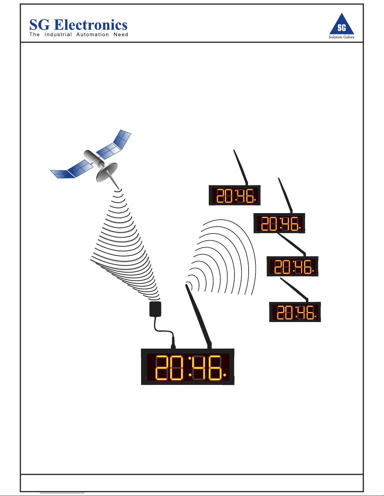
Main Clock
GPS
Clock 1
Clock 2
Clock 3
Clock 4
Specification
LED bar
4 * 2.3
4 Digit
1.
2.
Display Digit
LED matrix
LED matrix
Digit Size (in Inches)
6 * 4
8 * 4.5
4 Digit
4 Digit
Serial
Features
SGCLK044 SGCLK046 SGCLK048
3.
4.
5.
6.
7.
Number of Alarms
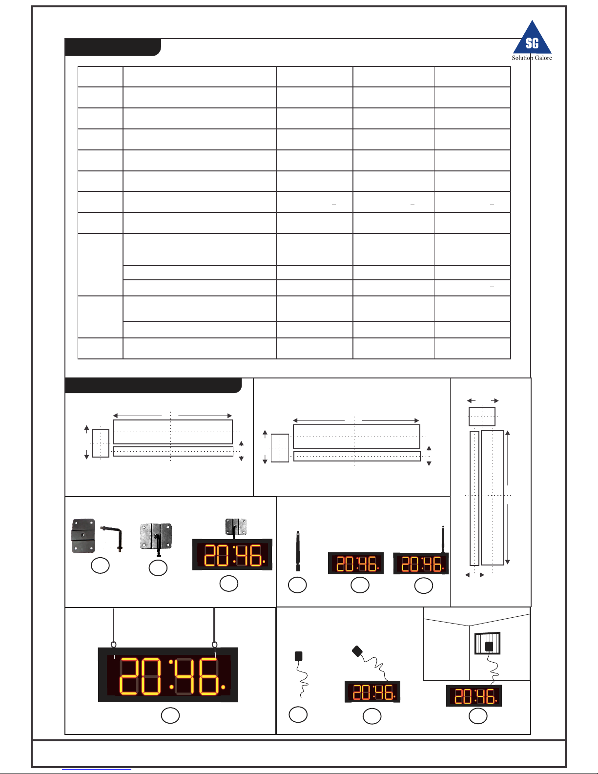
Clock Size (L*H*D, in Inches)
Time Format
12 Hrs & 24 Hrs
12 Hrs. & 24 Hrs.
12 Hrs. & 24 Hrs.
Power Requirement
220V, 50Hz AC+10%
220V, 50Hz AC +10%
220V, 50Hz AC+10%
Suspension Method
Mounting
Hanging
Hanging
34.25*10.125*3
30.25*8.125*3
18.25*7.25*3
16
16 16
Digital Clock User Manual 2
1
1
2
2
Hardware Design & Installation
8.
9.
10.
Calibration:
I) Through key panel
II) RS232 Interface With Computer
III) GPS Synchronization
In Build
In Build
In Build
In Build
In Build
In Build
In Build
In Build
In Build
Optional
Optional
Optional
Optional
Optional
Optional
Synchronization between clocks:
I) Through Wired Link (interface only)
II) Through Wireless link
Alarm Output
220 V AC 220 V AC
220 V AC
Height
7.25
Lenght
18.25
Width
3
SGCLK044
Height
8.125
Lenght
30.25
Width
3
SGCLK046
Height
10.125
Length
34.25
Width
3
SGCLK048
Mounting Process
Antenna Setting
GPS Setting
2
1
3
1
2
3
Hanging Method

Wire / Wireless Conection Process
Clock Key Calibration
Clock Key Calibration
Wire Connectivity
Master Clock
Slave Clock
2
1
2
3
4
5
Master Clock
Slave Clock
Slave Clock
Slave Clock
Slave Clock
1
2
3
4
5
1
2
3
4
5
1
2
3
4
5
1
2
3
4
5
12345-
(
)
TX
RX
GND
(
)
220V, 6A
AC, O/P
L
N
220V, 6A
AC, O/P
220V, 6A
AC, O/P
220V, 6A
AC, O/P
220V, 6A
AC, O/P
220V, 6A
AC, O/P
Cable Connectivity Details
SET
1
2
3
4
5
SG
Solution Galore
S.G.Electronics
www.sgelectronics.co.in
DIGITAL CLOCK
MODEL: SGCLK04
Sl. No.:
12345-
(
)
TX
RX
GND
(
)
220V, 6A
AC, O/P
L
N
Power Connection 220V, 50Hz, ±10%
Wire Connectivity
Wire Connectivity
Computer Calibration
Computer Calibration
GPS Calibration
GPS Calibration
Master Clock
Wireless Connection
Master Clock
Wireless Connection
Slave Clock
2
2
Slave Clock
1
2
3
4
5
Computer Clock
Slave Clock
Slave Clock
Slave Clock
Slave Clock
1
2
3
4
5
1
2
3
4
5
1
2
3
4
5
12345-
(
)
TX
RX
GND
(
)
220V, 6A
AC, O/P
L
N
1
2
6
3
7
4
8
5
9
1
2
3
4
5
6
7
8
9
Transmitted Data(TX)
Signal Ground(GND)
Receive Data(RX)
PIN
SIGNAL
220V, 6A
AC, O/P
220V, 6A
AC, O/P
220V, 6A
AC, O/P
220V, 6A
AC, O/P
1
2
3
4
5
Master Clock
Slave Clock
Slave Clock
Slave Clock
Slave Clock
1
2
3
4
5
1
2
3
4
5
1
2
3
4
5
1
2
3
4
5
12345-
(
)
TX
RX
GND
(
)
220V, 6A
AC, O/P
L
N
220V, 6A
AC, O/P
220V, 6A
AC, O/P
220V, 6A
AC, O/P
220V, 6A
AC, O/P
220V, 6A
AC, O/P
Main Clock
Clock 3
Clock 4
Digital Clock User Manual 3
GPS Calibration
MAINS 220VAC
1
2
3
4
5
12345-
(
)
TX
RX
GND
(
)
220V, 6A
AC, O/P
L
N
Alarm Sound Output Connection (220 V Ac 6 Amp )
GPS
Clock 1
Clock 2

School Hospital
Firm / Industries Transport
Broadcast & Telecast Defense
Digital Clock User Manual 4
Click here to check
com port connectivity
Click here to
Update Clock
Application
Alarm Duration
Click here to
set time format
Click here to
set 16 Alarm
Click here to
set alarm duration
Select COM Port
Update Clock
Exit
Alarm 1 time:
Alarm 9 time:
Alarm 2 time:
Alarm10 time:
Alarm 3 time:
Alarm 11 time:
Alarm 4 time:
Alarm12 time:
Alarm 5 time:
Alarm 13 time:
Alarm 6 time:
Alarm 14 time:
Alarm 7 time:
Alarm 8 time:
Apply
Reset All
Exit
Alarm15 time:
Alarm 16 time:
Apply
Select Time Format
Configure Time
Configure Time
Configure Alarm
Configure Alarm
12-Hrs
O
/
I
SG
Solution Galore
SG
Solution Galore
SG Electronics
The Industrial Automation Needs
SG Electronics
The Industrial Automation Needs
0 Sec
( in Seconds )
Clock Interface powered by SG Electronics
Clock Interface powered by SG Electronics
13:30
13:30
13:30
13:30
13:30
13:30
13:30
13:30
13:30
13:30
13:30
13:30
13:30
13:30
13:30
13:30
GUI Application Calibration
Key Calibration
Step1: First Press SET Key and switch ON digital Clock with holding SET for
2 Second continuously.
Step2: After 2 second, Digital Clock Minute Panel will be Blinking for time
calibration.
Step3:First set minute, then Press SET Key for Hour calibration.
After that press SET key for time calibrate and save into digital clock with 00
second by default.
Time Format Setting :
Step1: First press SET Key and Switch ON Digital clock and holding the
SET key for 10 Second Continuously.
Step2: After 10 second Digital clock screen has show firstly 12HR / 24HR
With Blinking digit.
Step3:after that we choose 12hr & 24 hr time format by pressing Down and
UP keys.
Step4: After Choose time format Press SET key for setting time format save
into digital clock.
Step1: First switch ON digital clock properly, then press SET key.
Step2: After Press SET key , digital clock screen has show AL 1(Alarm1).
Step3:After 2 second alarm time calibration will be show with
blinking digit of minute.
Step4 : after that minute will be setting by pressing DOWN and UP key then,
press SET key for Hours setting.
After setting hours into digital clock press SET key for other 15 alarm time
Setting.
Step6: Rest all 15 Alarm setting follow through exact instruction of alarm1.
Step7: After 16 Alarm time setting ,Alarm on will be show, which is represents to
alarm duration setting that is minimum 0 second and maximum 59 second.
1. Alarm time is always in 24 hrs format and this clock initially on any
inbuilt alarm, for alarm it provides 220V AC 6 Amp output.
2. By default time of the clock is calibrated with format of 12 hrs
with no alarm set.
3.If we set alarm 00:00 then alarm does not work.
*
*
*
*
In duration of setting, if we no touch any key of digital clock for 5 Second,
digital clock auto go back to main time screen.
06:28 PM
06:28 PM
Alarm Time Setting:
Time Calibration:
Apply
 Loading...