


µ-FLOWMETER
™
#206370 STANDARD MODEL
#206372 DELUXE MODEL
This simple easily installed device provides a ready measure of flowrates from conventional or micro HPLC pumps.
Section 1.0 Assembly Instructions
1.1 See Section 3.0 packing list and ensure that all components have been received. Notify SGE immediately of any
shortages.
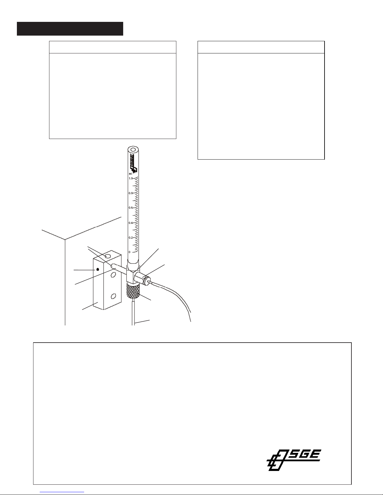
1.2 Refer to Fig. 1.
1.3 Identify the supporting bracket base (#1). This is supplied drilled to accommodate two 3mm (10G) screws for
mounting on a vertical or horizontal surface, immediately adjacent to the eluent exit of the detector.
Alternatively the block is also supplied with double sided adhesive tape for the same purpose.
1.4 Identify the valve and supporting arm assembly (# 2).
1.5 Identify two 5mm holes (# 4) in the supporting bracket base. These holes are to accept the supporting arm shaft
(# 5) in either the vertical or horizontal attitude. The supporting arm shaft is locked in place using the
set screw (# 6).
1.6 - # 206370 standard version.
Assemble the 1mL capacity flow tube into the threaded recess in the supporting arm and firm up finger tight.
1.6 - #206372 DeLuxe Version.
Select the appropriate flow tube from the three supplied. These are 1mL capacity, 250µL capacity and 50µL
capacity. Assemble the selected tube into the threaded recess in the supporting arm and firm up finger tight.
CAUTION DO NOT OVERTIGHTEN
1.7 Loosen the set screw (# 6) and adjust the orientation of the assembly until the flow tube is vertical. Re tighten the
screw.
1.8 Connect the effluent line from the detector into the side arm (# 7) using the nut (# 8) and sealing ring (# 9)
provided.
1.9 Position a "waste" solvent receptacle directly under the drain outlet (# 10).
NB Do not restrict this outlet in any way as excess back pressure can force liquid to rise in the flow tube which is
inappropriate, except when taking a measurement.
Section 2.0 Operation
2.1 Refer again to Fig. 1 and identify the waste on-off valve (# 3). This is operated by sliding it "up" or "down".
2.2 To take a measurement move the valve into the "down" position. This closes off the waste discharge.
2.3
Time the liquid as it rises over the scale in the flow tube.
2.4
At the completion of the measurement, move the valve to the "up" position. This will open the waste discharge and
empty the flow tube.
2.5 Close the valve by moving it downwards in order to repeat the measurement.
2.6 For normal operation, leave the valve in the "up" or open position.
UNITED STATES OF AMERICA
SGE, Incorporated
Telephone : +1-512-837 7190
Toll Free : (800) 945 6154
Fax : +1-512-836 9159
E-mail : usa@sge.com
AUSTRALIA AND PACIFIC REGION
SGE International Pty Ltd
Phone: +61-3-9837 4200
Fax: +61-3-9874 5672
E-mail: support@sge.com
UNITED KINGDOM
SGE Europe Ltd
Phone: +44-1908-568 844
Fax: +44-1908-566 790
E-mail: uk@sge.com
FRANCE
SGE Europe Ltd. (France)
Phone: +33-1-69 29 80 90
Fax: +33-1-69 29 09 25
E-mail: france@sge.com
GERMANY
SGE GmbH (Germany)
Phone: +49-6151-860 486
Fax: +49-6151-860 489
E-mail: germany@sge.com
JAPAN
SGE Japan Inc
Phone: +81-45-222 2885
Fax: +81-45-222 2887
E-mail: japan@sge.com
INDIA
SGE Laboratory Accessories Pvt Ltd
Phone: +91-22-24715896
Fax: +91-22-24716592
E-mail: sgeindia@vsnl.com
CHINA
SGE China Service Centre
Phone: +86-10-6588 8666
Fax: +86-10-6588 6577
E-mail: sales@jjindustries.com.cn
MIDDLE EAST
Tel: 00 971 - 6 - 557 3341
Fax: 00 971 - 6 - 557 3541
email: gulfsupport@sge.com
Publication No. MN-0248-A Rev:00 3/96
3.0 Packing Lists
# 206370 Standard Version
Support Bracket/Valve assembly x 1
1ml Flow Tube x 1
Nut, SSN-16 x 1
Sealing Ring, PSR-16 x 1
Allen Key x 1
Spanner 3/16 - 1/4 A.F. x 1
Mounting Block x 1
PTFE Tube, 0.5M x 1
Instruction Leaflet x 1
2
7,8,9
3
10
4
6
5
1
Figure 1.
# 206372 DeLuxe Version
Support Bracket/Valve assembly x 1
1ml Flow Tube x 1
250µL Flow Tube x 1
50µL Flow Tube x 1
Nut, SSA-16 x 1
Sealing Ring PSR-16 x 1
Allen Key x 1
Spanner 3/16 - 1/4 A.F. x 1
Mounting Block x 1
PTFE Tube 0.5M x 1
Instruction Leaflet x 1
 Loading...