

Page 1

Documentation
Vacuum leak detector VLXE ..
Please read the instructions before commencing any work
Last updated: 10/2019
Item no.: 602 222
Page 2

Contents
Table of Contents
1. General ....................................................................... 4
1.1 Information
1.2 Explanation of symbols
1.3 Limitation of liability
1.4 Copyright
1.5 Warranty
1.6 Customer Service
2. Safety .......................................................................... 6
2.1 Intended use
2.2 Responsibility of the operating company
2.3 Qualification
2.4 Personal protective equipment
2.5 Basic hazards
3. Technical Data ........................................................... 9
3.1 General data
3.2 Electrical data
3.3 Ex data
3.4 Switching values
3.5 Field of application
4. Design and function .................................................. 13
4.1 Design
4.2 Normal operation
4.3 Air leak
4.4 Liquid leak
4.5 Display and control elements
5. Installation of the system ......................................... 17
5.1 General notes
5.2 Installation of the leak detector
5.3 Pneumatic connection cables
5.4 Making pneumatic connections
5.5 Electrical lines
5.6 Electrical connection diagram
5.7 Installation examples
6. Commissioning ......................................................... 32
6.1 Tightness test
6.2 Commissioning of the leak detector
7. Functional check/maintenance ................................ 34
7.1 General
7.2 Maintenance
7.3 Functional check
8. Fault (Alarm) .............................................................. 39
8.1 Alarm description
8.2 Fault
8.3 Behavior
- 2 -
9. Spare parts ................................................................. 40
10. Accessories ............................................................... 41
VACUUM LEAK DETECTOR VLXE .. 31/10/2019
Page 3

Contents
11. Disassembly and disposal ........................................ 42
11.1 Disassembly
11.2 Disposal
12. Appendix ..................................................................... 43
12.1 Use on interstitial spaces that are
filled with leak detection liquid
12.2 Dimensions and drilling template
12.3 EU declaration of conformity
12.4 Declaration of performance
12.5 Manufacturer’s declaration of compliance
12.6 TÜV-Nord certification
31/10/2019 VACUUM LEAK DETECTOR VLXE ..
- 3 -
Page 4
General
1. General
Information
This manual provides important information about how to handle the
VLXE leak detector. The precondition for safe working is compliance
with all of the specified safety notices and instructions for action.
In addition, all the applicable local accident prevention regulations
and general safety instructions must be complied with at the operating site of the leak detector.
1.2 Explanation of symbols
Warnings in this manual are indicated by a symbol next to them.
The signal word expresses the level of risk.
DANGER:
An immediately hazardous situation that results in death or serious injuries if not avoided.
1.3 Limitation of liability
WARNING:
A potentially hazardous situation that can result in death or serious injuries if not avoided.
CAUTION:
A potentially hazardous situation that can result in minor or slight injuries if not avoided.
INFORMATION:
Highlights useful tips, recommendations and information.
All the data and information in this documentation have been compiled taking account of applicable standards and regulations, the current state of technology and our many years of experience.
SGB will not accept liability for:
Non-compliance with this manual
Unintended use
Deployment of unqualified personnel
Unauthorized conversions
Connection to systems not approved by SGB
1.4 Copyright
- 4 -
The contents, texts, drawings, pictures, and any other representations
are protected by copyright and are subject to industrial property
rights. Any misuse is a criminal offence.
VACUUM LEAK DETECTOR VLXE .. 31/10/2019
Page 5

1.5 Warranty
1.6 Customer Service
General
We provide 24 months of warranty on the VLXE .. leak detector from
the day of installation on-site in accordance with our General Terms
and Conditions of Sale and Delivery.
The warranty period is a maximum of 27 months from our date of
sale.
The prerequisite for any warranty is the presentation of the function/test report about initial commissioning by trained personnel.
Specification of the serial number of the leak detector is required.
The warranty obligation is rendered null and void in the case of
- inadequate or incorrect installation,
- improper operation,
- changes/repairs made without the agreement of the manufacturer.
Our Customer Service department is available to provide you with information.
You can find information about contacts on the World Wide Web at
www.sgb.de or on the rating plate of the leak detector.
31/10/2019 VACUUM LEAK DETECTOR VLXE ..
- 5 -
Page 6
Safety
2. Safety
2.1 Intended Use
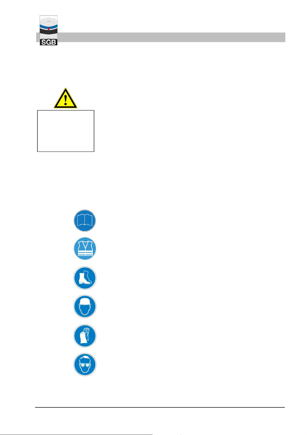
WARNING!
Danger from
misuse
Leak detector fitted in the open air outside the explosion hazard
area (also possible in the building under the conditions listed)
Conditions from Sec. 3.5 “Field of application” must be complied
with.
Pressureless double-walled tanks and pressureless double-walled
pipes, if any explosive steam-air-mixtures and vapors that occur
comply with these conditions:
o Explosion group IIA to IIB3
o Temperature class T1 to T3
o Must be heavier than air
Double-walled pipes with up to 5 bar conveyance pressure in the
inner pipe for liquids with a flashpoint > 60 °C (for Germany 55 °C)
and which end in the ex-area. Possible steam-air-mixtures and vapors must comply with the following conditions:
o Explosion group IIA to IIB3
o Temperature class T1 to T3
o Must be heavier than air
Only for monitoring spaces of double-wall tanks/pipelines with suf-
ficient resistance to underpressures
Tightness of the monitoring spaces according to this documenta-
tion (Chap. 6.1.).
Detonation flame arresters are to be used on the vessel/pipe.
Ambient temperature -40°C … +60°C
Penetrations in the manhole or control shafts must be closed off so
that they are gas-tight
Power connection cannot be switched off
Earthing/equipotential bonding in accordance with applicable regu-
lations
Mains earth may be on the same potential as the equipotential
bonding of the tank/pipeline
Any claims resulting from misuse will not be accepted.
2.2 Responsibility of the operating company
The VLXE leak detector is used in the industrial sector. The operating
company must therefore comply with statutory occupational health
and safety requirements.
In addition to the safety information in this documentation, all the ap-
WARNING!
Hazard in the
case of incom-
plete documen-
tation
plicable safety, accident prevention and environmental protection
regulations must be complied with. In particular:
- Compilation of a hazard analysis and implementation of its results
in operating instructions
- Regular checking of whether the operating instructions comply with
the current state of regulations
- 6 -
VACUUM LEAK DETECTOR VLXE .. 31/10/2019
Page 7
- The content of the operating instructions may also be the reaction
to a possible alarm
- Instigation of an annual functional check
2.3 Qualification
The personnel must be sufficiently qualified to recognize and avoid
possible dangers on their own.
Companies that put the leak detector into operation should have been
WARNING!
Danger to people
and environment in
case of insufficient
qualification
trained at SGB, by SGB or by the authorized representative.
National regulations must be complied with.
For Germany: Specialist company qualification for the installation,
commissioning and maintenance of leak detection systems.
2.4 Personal protective equipment (PPE)
Safety
Personal safety equipment must be worn during work.
- Wear the necessary protective equipment for the respective work
- Observe and comply with any signs concerning PPE
- For additional information see 12.2
Entry in the "Safety Book"
"Wear a warning vest"
Wear safety shoes
Wear a protective helmet
Wear gloves - where necessary
Wear protective goggles - where necessary
31/10/2019 VACUUM LEAK DETECTOR VLXE ..
- 7 -
Page 8
Safety
2.41 Personal protective equipment when working on systems which pose an explosion hazard
The parts listed here apply in particular to safety when working on
systems which pose an explosion hazard.
If work is carried out in areas with a potentially explosive atmosphere,
the following items of equipment are required as an absolute minimum:
Suitable clothing (risk of a build-up of electrostatic charge)
Suitable tools (compliant with EN 1127)
A suitable gas warning device which is calibrated for the existing
vapor-air mixture (work should only be performed at a concentra-
1
tion of 50 % below the lower explosion limit)
Measuring device for determining the oxygen content of the air
(Ex/O meter)
2.5 Basic hazards
DANGER:
From electric current
When working on the opened leak detector, it must be disconnected
from the power supply unless otherwise stated in the documentation.
Comply with the relevant regulations for electrical installations, explo-
sion protection (e.g. EN 60 079-17) and accident protection regulations.
CAUTION:
Through moved parts
If work is carried out on the leak detector, switch off the power supply.
DANGER:
From explosive vapor-air mixtures
There may be explosive steam-air mixtures in the leak detector and in
the connection lines.
The absence of gas must be established before carrying out work.
Comply with explosion protection regulations, such as the German
BetrSichV (or the Directive 1999/92/EC and the resulting laws in the
respective member states) and/or others.
DANGER:
When working in shafts
The leak detectors are fitted outside the manhole shafts. The pneu-
matic connection is typically made in the manhole shaft. The shaft
should therefore be entered for the installation.
Before entry, the appropriate protection measures must be installed
and the absence of gas and sufficient oxygen must be ensured.
1
Other percentages may be applicable according to national, regional or plant-specific regulations.
- 8 -
VACUUM LEAK DETECTOR VLXE .. 31/10/2019
Page 9
3. Technical data of the leak detector
3.1 General Data
Dimensions and drilling template see Sec. 12.3
Weight 8.3 kg
Storage temperature range -40°C to +60°C
Use temperature range -40°C to +60°C
Buzzer volume Summer > 70 dB(A) in 1 m
Protection rating of the housing IP54
3.2 Electrical data
Supply voltage 100…240 VAC, 47-63 Hz
Power consumption 50 W (including heating)
Technical Data
optionally: 24 VDC
3.3 Ex data
3.4 Switching values
Terminals 5, 6, external signal: max. 24 VDC; max. 300 mA
Terminals 11…13, potential-free: DC: ≤ 25 W or. AC ≤ 50 VA
terminals 17…19, potential-free: DC: ≤ 25 W or AC ≤ 50 VA
Fuse: max. 10 A, 1500 A breaking
capacity
Overvoltage category: 2
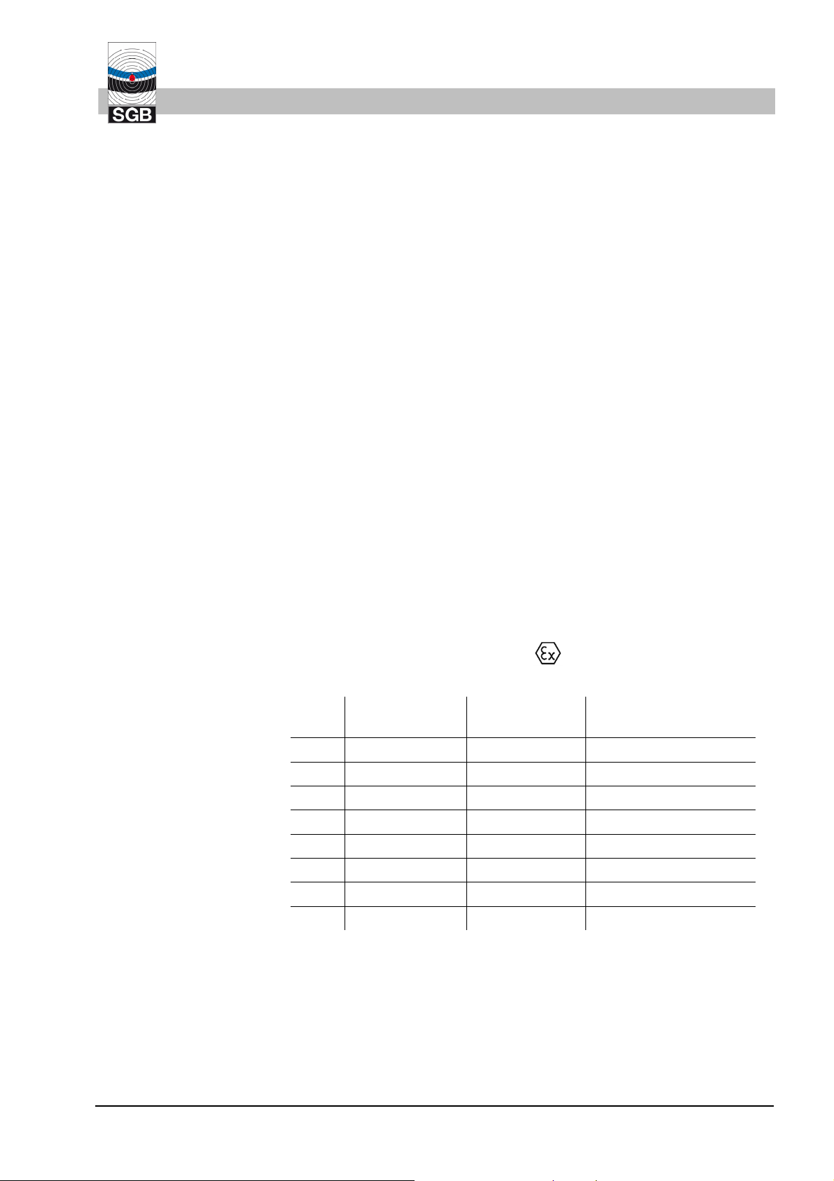
Important:
only pneumatic part II 1/2G Ex c IIB3 T4 Ga/Gb
Type Alarm ON,
at the latest at:
34 -34 mbar -100 mbar -250 mbar
80 -80 mbar -140 mbar -400 mbar
230 -230 mbar -360 mbar -650 mbar
255 -255 mbar -380 mbar -650 mbar
330 -330 mbar -450 mbar -700 mbar
Pump OFF,
not more than:
Functional capability* of the IS** for
31/10/2019
410 -410 mbar -540 mbar -750 mbar
500 -500 mbar -630 mbar -850 mbar
570 -570 mbar -700 mbar -900 mbar
Special switching values can be agreed between the customer and
SGB.
* Lower values can be agreed, but an underpressure valve must then
be integrated into the leak detector.
** interstitial space
VACUUM LEAK DETECTOR VLXE ..
- 9 -
Page 10
Technical Data
3.5 Field of application
3.5.1 Vessel
a) Single-walled (underground/above-ground), cylindrical tanks with
leak protecting lining (LPL) or leak protecting jacket (LPJ) and the
suction line up to the low point
Usage limits: none in relation to density and diameter
b) Double-walled, horizontal cylindrical tanks (underground/above-
ground) (e.g. DIN 6608-2, 6616 or DIN EN 12 285-1-2)
- as with a), but without suction line to low point
- as with c), but without suction line to low point
- as with d), but without suction line to low point
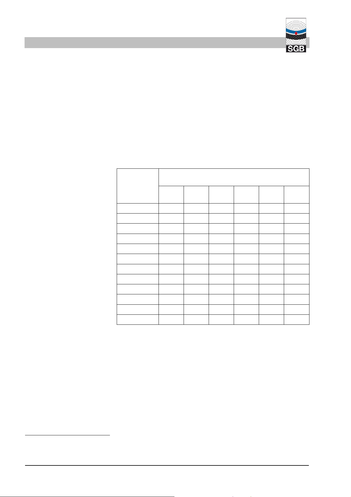
Usage limits:
H
Density of
the material
being stored
3
[kg/dm
]
Vessel height or height from low point of the
max.
pipe to the node point
2
[m]
230 255 330 410 500 570
0.8 2.6 2.9 3.8 4.8 6.0 6.9
0.9 2.3 2.6 3.4 4.3 5.3 6.1
1.0 2.0 2.3 3.1 3.9 4.8 5.5
1.1 1.9 2.1 2.8 3.5 4.4 5.0
1.2 1.7 1.9 2.6 3.2 4.0 4.6
1.3 1.6 1.8 2.4 3.0 3.7 4.2
1.4 1.5 1.6 2.2 2.8 3.4 3.9
1.5 1.4 1.5 2.0 2.6 3.2 3.7
1.6 1.3 1.4 1.9 2.4 3.0 3.4
1.7 1.2 1.4 1.8 2.3 2.8 3.2
1.8 1.1 1.3 1.7 2.2 2.7 3.1
1.9 1.1 1.2 1.6 2.0 2.5 2.9
For underground systems at least density 1 is to be assumed.
In above-ground systems, the leak detector is to be fitted above
the top of the tank.
c) Double-walled (including single-walled with leak protecting lining or
leak protecting jacket) cylindrical standing vessels or tanks with
curved floors (underground/above-ground) with a suction line up to
the low point (DIN 6618-2: 1989)
2
Node point is the junction of the suction and measuring line with a vacuum leak detector for pipes. This can
also be in the assembly kit or a manifold.
- 10 -
VACUUM LEAK DETECTOR VLXE .. 31/10/2019
Page 11

Usage limits:
Technical Data
Diameter
[mm]
1600
2 000
2500
2900
Height
[mm]
Max. density of the material being
stored
3
[kg/dm
]
34 230 255 330 to 570
2,820 1.9 1.9 1.9 1.9
3,740 1.6 1.9 1.9 1.9
5,350 1.6 1.9 1.9 1.9
6,960 1.6 1.9 1.9 1.9
5,400 1.4 1.9 1.9 1.9
6,960 1.4 1.9 1.9 1.9
8,540 1.4 1.9 1.9 1.9
6,665 1.0 1.9 1.9 1.9
8,800 1.0 1.9 1.9 1.9
8,400 0.9 1.9 1.9 1.9
9,585 0.9 1.9 1.9 1.9
12,750 0.8 1.2 1.2 1.6
15,950
-
1.0 1.0 1.2
d) Right-angle or cylindrical tanks or tubs with flat floors (double-
walled or LPL or LPJ) with suction line to low point
Density of
the material
H
[m]
max.
being stored
[kg/dm
3
]
34 230 255 330 410 500 570
0.8 7.5 17.3 19.1 23.4 23.8 24.5 24.2
0.9 6.6 15.3 17.0 20.8 21.1 21.8 21.5
1.0 6.0 13.8 15.3 18.7 19.0 19.6 19.4
1.1 5.4 12.6 13.9 17.0 17.3 17.8 17.6
1.2 5.0 11.5 12.8 15.6 15.8 16.4 16.2
1.3 4.6 10.6 11.8 14.4 14.6 15.1 14.9
1.4 4.3 9.9 10.9 13.4 13.6 14.0 13.8
1.5 4.0 9.2 10.2 12.5 12.7 13.1 12.9
1.6 3.7 8.6 9.6 11.7 11.9 12.3 12.1
1.7 3.5 8.1 9.0 11.0 11.2 11.5 11.4
1.8 3.3 7.7 8.5 10.4 10.6 10.9 10.8
1.9 3.1 7.3 8.1 9.8 10.0 10.3 10.2
31/10/2019 VACUUM LEAK DETECTOR VLXE ..
- 11 -
Page 12

Technical Data
3.5.2 Pipes/tubes
In the design manufactured either in the plant or on-site
Usage limits: in accordance with the Table in Sec. 3.5.1 in b), where
the height between the low point of the interstitial space and the node
point (junction of the suction line and measuring line, generally in the
assembly kit or manifold, see also 5.7.4 ff) is to be used instead of the
tank diameter.
- Suction lines: The alarm underpressure must be at least 30 mbar
greater than the max. underpressure in the inner pipe at the highest point of the interstitial space
- Pressureless lines such as filling lines
- Pressure-controlled pipelines with up to 5 bar overpressure (only if
flash point > 60 °C), see also chap. 2.1.
- In special application cases (individual pressureless pipeline, gra-
dient to a point) the VLXE 34 design can also be used.
3.5.3 Monitorable fluids
- For Germany: with usability certificate from construction oversight
authority
Note: Double-walled fittings may also be integrated into the pipeline.
Double-walled fittings can also be monitored for themselves with this
leak detector. The installation examples for pipes are to be applied
analogously.
Water-polluting liquids with a flashpoint ≤ 60°C (for Germany the limit
is 55°C in accordance with TRGS 509 and 751), such as fuels and
combustibles.
The following conditions also apply:
- The materials used must be resistant to the liquids being moni-
tored.
- Water-polluting liquids with flashpoint ≤ 60 °C (for Germany the
1
limit is 55 °C in accordance with TRGS 509 and 751)
and flashpoint > 60 °C (for Germany the limit is 55 °C in accordance with
TRGS 509 and 751) with possible explosive vapor-air mixtures
(e.g. due to outgassing).
These possible explosive vapor-air mixtures must be heavier than
air and classifiable into Explosion group IIA or IIB as well as in
temperature class T1 to T3, such as fuel e.g. (petroleum).
- 12 -
- If different water-polluting liquids are being conveyed in single
pipes and monitored with a leak detector, these liquids must not
negatively influence one another and the mixture must not lead to
chemical reactions.
VACUUM LEAK DETECTOR VLXE .. 31/10/2019
Page 13
4. Design and function
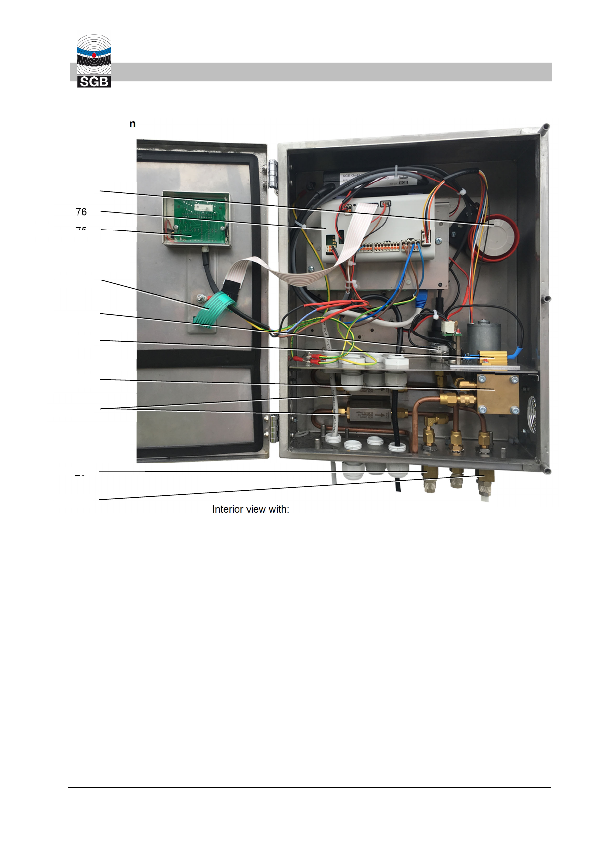
4.1 Design
69
Design and function
76
75
139
102
91
60
18
20
21
Interior view with:
18 Detonation flame arrester
20 Three-way valve in suction line
21 Three-way valve in measuring line
60 Vacuum pump
69 Buzzer
75 Display board
76 Main circuit board
91 Heater
102 Pressure sensor
139 Membrane keyboard
4.2 Normal operation
31/10/2019
The vacuum leak detector is connected to the interstitial space
through the suction, measurement and connection line(s). The underpressure generated by the pump is measured by a pressure sensor
and regulated.
When the operating underpressure (Pump OFF) is reached the pump
is switched off. Due to small leaks in the leak indication system which
are unavoidable, the underpressure will slowly start to fall. When the
Pump ON switching value is reached, the pump is switched on and
VACUUM LEAK DETECTOR VLXE ..
- 13 -
Page 14

Design and function
4.3 Air leak
the interstitial space is evacuated until the operating underpressure
(Pump OFF) is reached.
Depending on the level of tightness and temperature fluctuation in the
overall system, the underpressure alternates between the Pump OFF
switching value and the Pump ON switching value, with short pump
running times and longer down times.
If an air leak occurs (in the outer wall or inner wall, above the fluid
level), the underpressure pump switches on, in order to restore the
operating underpressure. If the volume of air flowing in through the
leak exceeds the limited conveying quantity of the pump, the pump
continues to run.
Increasing leak rates lead to a further drop in underpressure (with
pump running) until the switching value “Alarm ON” is reached. Visual
and audible alarm signals are then triggered.
4.4 Liquid leak
If there is a liquid leak, liquid penetrates the interstitial space and collects at the bottom of the interstitial space.
The liquid entering lowers the underpressure, the pump is switched
on and evacuates the interstitial space(s) until the operating underpressure is reached. This process is repeated multiple times until the
liquid stop valve in the suction line is closed.
Due to the underpressure still existing on the measuring line side, further fluid leaks will be sucked into the interstitial space, the measuring
line and, if appropriate, the pressure compensation vessel. This leads
to a decline in underpressure until the “Alarm OFF” pressure is
reached. Visual and audible alarm signals are then triggered.
Note: A liquid sensor connected to a magnetic valve can optionally be
used instead of a liquid stop valve. The liquid alarm is then triggered
by the liquid’s contact with the sensor.
- 14 -
VACUUM LEAK DETECTOR VLXE .. 31/10/2019
Page 15
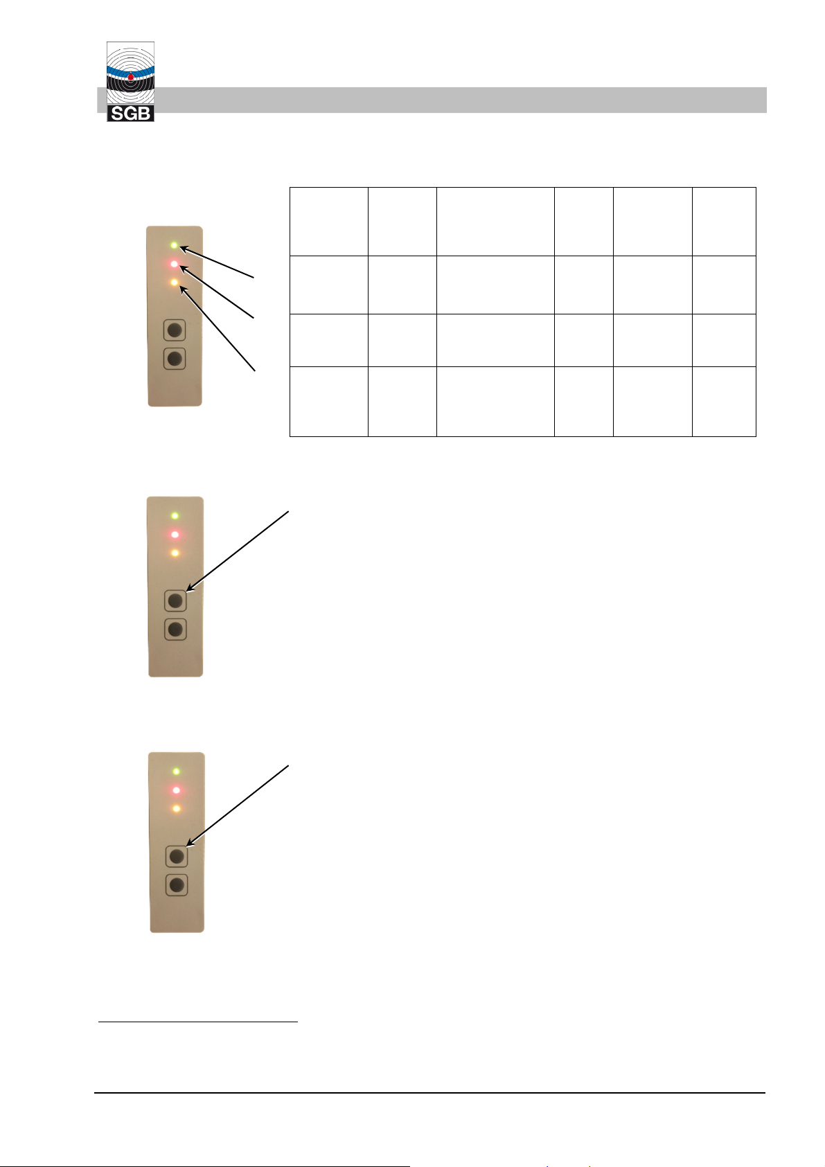
4.5 Display and control elements
4.5.1 Display
Signal
lamp
OPERATION:
green
ALARM:
red
ALARM
2:
yellow
Design and function
Operating status
Alarm, underpressure below
“Alarm ON”
Alarm
probe
Magnetic
valve fault
Device
fault
ON ON ON ON ON
OFF ON (flashing)
3
OFF
ON
(flashing)
ON4
ON
OFF OFF
(flash-
ON OFF
ing)
4.5.2 Function: "Switch off audible alarm signal"
Briefly press the "Mute" button once. The audible alarm signal is then
switched off and the red LED flashes.
Pressing the button again switches on the audible signal.
This function is not available in normal operation and for malfunc-
tions.
4.5.3 Function: "Test visual and audible alarm signal"
Press the "Mute" button and keep it pressed (approx. 10 seconds).
The alarm signal is triggered until the button is released again.
This test is only possible if the pressure in the system has exceeded
the "Alarm OFF" pressure level.
3
(flashing) is always active when acknowledged external signal is active.
4
The “Audible alarm” button has no function, meaning the acoustic signal cannot be stopped.
31/10/2019
VACUUM LEAK DETECTOR VLXE ..
- 15 -
Page 16

(
Design and function
4.5.4 "Leak tightness check” function
Press the "Mute" button and keep it pressed until the "Alarm" signal
103)
lamp flashes quickly, then release. A value for the leak tightness is
shown on the display (103). The same value is indicated by the number of times the “Alarm” signal lamp flashes.
After 10 seconds this display goes off and the current underpressure
in the system is shown again.
For the "Test leak tightness" function, the leak detector must have
performed at least 1 automatic feed interval in normal operation (i.e.
without being filled/evacuated by an assembly pump) in order to obtain a valid result.
It is recommended to make this test before performing any recurring
functional test of a leak detector. This makes it possible to directly assess whether to look for leaks.
Number of flashing signals Assessment of the leak tightness
0 Very leak tight
1 to 3 Leak tight
4 to 6 Sufficiently leak tight
7 to 8 Maintenance recommended
9 to 10 Maintenance urgently recommended
The smaller the above value, the tighter the system is. The meaningfulness of this value also depends on temperature fluctuations and
should therefore be considered an indicative value.
- 16 -
VACUUM LEAK DETECTOR VLXE .. 31/10/2019
Page 17

5. Installation of the system
5.1 General Information
- Before starting work, the documentation must be read and understood. If anything is unclear, please contact the manufacturer.
- Take manufacturer approvals into account for the vessel/pipe or
the interstitial space.
- The safety instructions in this documentation must be observed.
- Installation and start-up must only be performed by qualified firms
- Feedthroughs for pneumatic and electrical connection lines, via
which the Ex atmosphere can spread, must be sealed so that they
are gas-tight.
- Comply with the relevant regulations for electrical installations, explosion protection (e.g. EN 60 079-14, EN 60 079-17) and accident
protection regulations.
Installation
5
.
- Comply with explosion protection regulations, such as the German
BetrSichV (or the Directive 1999/92/EC and the resulting laws in
the respective member states) and/or others.
- Pneumatic connections, connection lines and fittings must be designed in at least PN 10 for the entire temperature range that may
occur.
- Before entering inspection shafts check the oxygen content and, if
necessary, flush the inspection shaft.
- When metal connection lines are used, it must be ensured that the
mains power supply earth has the same potential as the
tank/piping to be monitored.
5.2 Installation of the leak detector
- Wall installation using the supplied installation material.
- Outside the explosion hazard area in the open air, without other
protective boxes, but not in shafts or tanks.
Over shafts and tanks only if these will be or are defined as explosion hazard zones.
- If the installation is to take place in an enclosed area, it must be
well ventilated. The basis for the assessment by the operating
company is EN 60 079-10/EN 13 237.
- To avoid excessive heating, the leak detector may not be fitted directly alongside heat sources.
The ambient temperature may not exceed 60°C. Appropriate
measures may need to be taken (e.g. installing a sunroof to limit
solar radiation).
5
For Germany: "qualified firms" in the sense of the Water Act, which have demonstrated their qualification
for installing leak detection systems.
31/10/2019 VACUUM LEAK DETECTOR VLXE ..
- 17 -
Page 18

Installation
- If the leak detector is used on containers with internal overpressures of max. 50 mbar (e.g. Gas recirculation), it must be fitted at
least 1 meter above the top of the vessel.
- Air supply and ventilation lines must be kept clear.
- Integrate the leak detector housing into the equipotential bonding
system.
5.3 Pneumatic connection cables
5.3.1 Requirements
- At least 6 mm clearance
- Resistance to the stored or conveyed product
- At least PN 10 over the complete temperature range
- The full cross-section must be retained (do not bend)
- Color coding:
Measuring line: RED
Suction line: WHITE or CLEAR
Exhaust: GREEN
5.3.2 Exhaust
- The length of the cables between the interstitial space and the leak
detector should not exceed 50 m. If the distance is greater, a larger cross-section is to be used. Special conditions apply to the exhaust line, see Sec. 5.3.1.
- Condensate traps should be fitted at all of the lowest points of the
connection lines.
- Fit liquid stop valve in the suction line (generally a part of the
mounting kit).
- If liquids are being stored or conveyed for which explosion protection regulations must be complied with, suitable detonation flame
arresters must be fitted at the connection to the interstitial space.
- The length of the exhaust line may not exceed 35 m. The manufacturer should be contacted if this is not enough.
- The exhaust line is generally led to the tank ventilation line, a detonation flame arrester being fitted immediately before connection
to the tank ventilation line.
- Exceptions from the recirculation of the exhaust to tank ventilation:
such as double-walled pipes or comparable:
o Exhaust ends in the open air, in a safe
6
space, outside the explosion protection area:
Provide condensate trap and liquid stop valve in the exhaust
line, apply Zone 1 conditions in a 1 m circle around the end of
the exhaust, affix warning notice if appropriate.
6
Among other things, not accessible to public traffic / people
- 18 -
VACUUM LEAK DETECTOR VLXE .. 31/10/2019
Page 19

o The exhaust ends in Zone 1 (for example remote filling shaft or
catch area):
A detonation flame arrester is provided at the end of the exhaust line
7
. Condensate traps are to be provided at low points;
the liquid stop valve can be dispensed with if the end of the exhaust ends in an area that is liquid-tight according to the Water
Act (e.g. catch surface).
- Note: under some circumstances an exhaust line ending in the
open air must be marked with warning notices.
5.3.3 Several pipelines/interstitial spaces connected in parallel
- Lay connection lines at a gradient towards the interstitial space or
distributor. Fit condensate traps at low points in connection lines
and at all low points when laying simultaneously in the open air.
- Lay suction and measuring line at gradient to the distributor. If this
is not possible, place condensate traps at all low points.
Installation
- Connect a liquid stop valve in every connection line to the interstitial space against the block direction.
This can prevent leaked fluid penetrating the interstitial spaces of
the other pipelines.
- If shut-off cocks are fitted in these connection lines, they should be
sealable in the open position.
- For pressure compensation vessel applications, see (p. 5.7.4 and
5.7.5):
Length of the measuring line from the pressure compensation ves-
8
sel (V=0.1 l)
Model 230…330: L
Model 410 L
Model 500 L
Model 570 L
:
max
max
max
max
16 m
12 m
10 m
8 m
IMPORTANT: The lower edge of the pressure compensation vessel may not be lower than the node point. The upper edge of the
pressure compensation vessel may not be more than 30 cm above
the node point.
Per 10 ml of the condensate trap(s) used in the measuring line between the pressure compensation vessel and the leak detector
L
falls by 0.5 m
max
- OR (as an alternative to the pressure compensation vessel)
50% of the entire measuring line length must be laid at a gradient
of 0.5 to 1% to the node point.
= 0.5 x entire length of the measuring line.
L
min
7
The detonation flame arrester can be dispensed with if the exhaust is laid in such a way that it is frost-free
and kinking (e.g. laying in the protective pipe) or stopping up of the exhaust can be excluded.
8
Multiplying this volume leads to the same multiplying of L
31/10/2019 VACUUM LEAK DETECTOR VLXE ..
max
.
- 19 -
Page 20

Installation
5.3.4 Several pipelines/interstitial spaces connected in series
The liquid stop valves (27*) connected against the direction of flow
prevent the other interstitial spaces being filled with leaked fluid if
there is a leak in the pipeline.
The interstitial space volumes for the connected pipelines must comply with the following conditions:
3∙V
IS 1
3∙V
IS 2
V
IS (number)
> V
> V
IS 1
IS 2
+ V
+ V
IS 2
IS 3
+ V
+ V
IS 3
IS 4
+ V
etc.
IS 4
is the volume of the particular interstitial space. No. 1 is the
interstitial space to which the suction line is connected (see 5.7.6)
5.4 Making pneumatic connections
5.4.1 Fitting the connection to the vessel interstitial space
(1) Generally according to the guidelines of the container manufac-
turer.
(2) SGB offers assembly kits with various connection kits.
and
5.4.2 Fitting the connection to the pipe interstitial space or test valves
(1) Generally according to the requirements of the manufacturer of
the pipeline / interstitial space.
(2) If Schrader valves are used, the following points must be noted:
- Unscrew protective cap
- Tighten lock nut
- Unscrew valve insert and stick up next to the connection with
a piece of adhesive tape. (as proof of the disassembly)
- Screw on connection to the interstitial space or test valve and
tighten by hand.
- Tighten if necessary, with suitable pliers.
5.4.3 Between the leak detector and the interstitial space
(1) Select and lay suitable pipe.
(2) When laying the pipe, check again that the hoses are protected
against damage when entering the manhole shaft.
(3) Make the appropriate connection (as shown in the following pic-
tures).
5.4.3.1 Flange screw connections (for flanged pipes)
- 20 -
(1) Oil O-rings
(2) Insert intermediate ring loosely in the coupling connecting piece
(3) Push union nut and compression ring over the pipe
(4) Tighten the union nut by hand
(5) Tighten union nut until increased force is clearly noticeable
(6) Final assembly: turn further by ¼ turn
VACUUM LEAK DETECTOR VLXE ..
31/10/2019
Page 21

5.4.3.2 Clamping ring screw fitting for metal and plastic pipes
(1) Insert support sleeve (only plastic pipe) into the pipe end
(2) Insert pipe (with support sleeve) as far as the stop
(3) Tighten nut of screw connection by hand to the resistance; then
turn further 1¾ turns with the wrench
(4) Loosen nut
(5) Tighten nut by hand until stop is felt
(6) Final fitting of the screw connection by tightening ¼ turn
5.4.3.3 Quick screw connection for PA pipe
(1) Cut the PA pipe to length at a right angle
(2) Unfasten the union nut and push it over the pipe end
(3) Push the pipe onto the nipple up to the start of the thread
(4) Tighten the union nut by hand
Installation
(5) Tighten the union nut with a spanner until there is a noticeable
increase in force (approx. 1 to 2 turns)
5.5 Electrical lines
Mains power connection:
Suggested cable: Ölflex Classic 100
- 2.5 mm
- 1.5 mm
Floating contacts and external signal
Suggested cable: Ölflex Truck 1700
- 1.5 mm
- 0.75 mm
Must be resistant to liquids that are stored/transported!
5.6 Electrical connection diagram
(1) Power supply: as printed on the manufacturer’s plate.
(2) Hard wire electrical connections, without plug-in or switch con-
nections.
(3) Comply with regulations regarding electrical installations, and, if
appropriate, those of the electricity supply company.
2
without wire end ferrule
2
with wire end ferrule and plastic collar
2
without wire end ferrule
2
with wire end ferrule and plastic collar
31/10/2019
VACUUM LEAK DETECTOR VLXE ..
- 21 -
Page 22

Installation
(4) Terminal assignment: (See also block diagram Sec. 5.6.3)
1/2 Mains power supply connection (100…240 V AC)
PE Earth for the mains power supply connection
3/4 assigned (vacuum pump)
5+/6- External signal (assigned to internal buzzer if applicable)
24 V DC
9/10 Special contacts, the potential-free contacts of a leak
detection probe can be connected here.
11/12 Potential-free contacts (open in the event of an alarm
and in the event of a power failure)
12/13 as above, however closed contacts
17/18 Potential-free contacts, parallel to the pump start (closed
at pump standstill and in the event of a power failure)
18/19 as above, however open contacts
21/22 Connected (to internal pressure sensor)
40+/41- 24 V DC as permanent power supply for supplying other
components or the power supply is connected here for a
device using 24 V DC supply voltage.
(5) Only apply power when all electrical and pneumatic lines are
5.6.1 Connection of the wires
(1) Press in the orange point using a screwdriver. This opens the
(2) Insert cable into the opened terminal.
(3) Hold cable in place and remove screwdriver.
connected and the housing lid is closed.
tension spring of the terminal.
- 22 -
VACUUM LEAK DETECTOR VLXE ..
31/10/2019
Page 23

(4) Check cable for tightness and connect other cables to the termi-
5.6.2 Equipotential bonding
- The housing of the leak detector is to be incorporated into the
- The fittings in the connection lines also need to be integrated into
Installation
nals in the same way.
equipotential bonding of the entire system using the bolts provided.
the equipotential bonding system, particularly if plastic pipes (connection lines to the tank) have been used.
- Before replacing a leak detector, disconnecting lines or similar
work, ensure that equipotential bonding is maintained (pull electrically conducting bridge if applicable).
31/10/2019 VACUUM LEAK DETECTOR VLXE ..
- 23 -
Page 24

Installation
5.6.3 Block diagram (SL 854 210)
8765432
1
L
60 Pump (24 V DC)
69 Buzzer, if applicable
76 Main circuit board
91 Heater
102 Pressure sensor
103 Display
116 Power supply 24 V DC
139 Membrane keyboard
140 Contacts for serial data transfer
141 Membrane keyboard connection strip
146 Magnetic valve monitoring boards
149 Ethernet board (if available)
150 PCB for maintenance display
91
102
116
~
-
+
149
Probe
RX
Data
N(-) N
L(+)
GND
140
76
146
1615
103
69
150
139141
60
M
N
PE
7
3
3
6
24V
DC
40
41
43
21
22
6
17
18 5
N
N
L
L
- 24 -
VACUUM LEAK DETECTOR VLXE .. 31/10/2019
Page 25

5.7 Installation examples
5.7.1 Cylindrical tank with LPL and suction line to low point
20
68
21
03 43
27
02
82
18
101
73
02 Stop cock
03 Exhaust
18 Detonation flame arrester
20 Three-way valve, suction line
21 Three-way valve, measuring line
27 Liquid stop valve
43 Measuring line
68 Suction line
73 Interstitial space
82 Nozzle for installation pump
101 Suction line to low point
Ex
Ex
101
68
Installation
43
73
31/10/2019 VACUUM LEAK DETECTOR VLXE ..
- 25 -
Page 26

Installation
5.7.2 Cylindrical, horizontal tank, double-walled, steel, without suction line to low point
Ex
20
21
43
Ex
68
27
02
03
82
18
max
H
02 Stop cock
03 Exhaust
18 Detonation flame arrester
20 Three-way valve, suction line
21 Three-way valve, measuring line
27 Liquid stop valve
43 Measuring line
68 Suction line
73 Interstitial space
82 Nozzle for installation pump
73
- 26 -
VACUUM LEAK DETECTOR VLXE .. 31/10/2019
Page 27

Installation
5.7.3 Cylindrical, standing tank with suction line led down in accordance with DIN 6618-2
02
27
82
18
73
101
20
21
43
68
03
33
Ex
Ex
02 Stop cock
03 Exhaust
18 Detonation flame arrester
20 Three-way valve, suction line
21 Three-way valve, measuring line
27 Liquid stop valve
33 Condensate trap
43 Measuring line
68 Suction line
73 Interstitial space
82 Nozzle for installation pump
max
H
31/10/2019 VACUUM LEAK DETECTOR VLXE ..
- 27 -
Page 28

Installation
5.7.4 Double-walled pipe (as per 3.5.2), connected in parallel 1
20
68
21
43
27
96
max
H
max
H
max
H
57
02 Stop cock
03 Exhaust
18 Detonation flame arrester
20 Three-way valve, suction line
21 Three-way valve, measuring line
27 Liquid stop valve
27* Liquid stop valve, connected against the direction of flow
33 Condensate trap
43 Measuring line
Ex
Ex
95
27*
barbarbar
02
88
57 Test valve
68 Suction line
74 Connecting line
82 Nozzle for installation pump
88 Double-walled tube
95 Expansion vessel
96 Node point
74
18
- 28 -
VACUUM LEAK DETECTOR VLXE .. 31/10/2019
Page 29

5.7.5 Double-walled pipe, connected in parallel 2
20
68
27
96
57
02 Stop cock
03 Exhaust
18 Detonation flame arrester
20 Three-way valve, suction line
21 Three-way valve, measuring line
27 Liquid stop valve
27* Liquid stop valve, connected against the direction of flow
43 Measuring line
44 Solenoid valve
57 Test valve
68 Suction line
74 Connection line
82 Nozzle for installation pump
88 Double-walled pipe
95 Pressure compensation vessel
96 Node point
Installation
Ex
Ex
21
43
27*
barbarbar
95
88
02
max
< H
max
< H
max
74
18
< H
31/10/2019 VACUUM LEAK DETECTOR VLXE ..
- 29 -
Page 30

Installation
5.7.6 Double-walled pipe, connected in series
max
27
0 < .... < H
02 Stop cock
03 Exhaust
18 Detonation flame arrester
20 Three-way valve, suction line
21 Three-way valve, measuring line
27 Liquid stop valve
43 Measuring line
57 Test valve
68 Suction line
74 Connection line
82 Nozzle for installation pump
88 Double-walled pipe
95 Pressure compensation vessel
96 Node point
20
68
27
Ex
88
V
ÜR 1
V
ÜR 2
Ex
18
82
02
18
21
43
95
02
- 30 -
VACUUM LEAK DETECTOR VLXE .. 31/10/2019
Page 31

5.7.7 Double-walled pipe, individual pipe with low vacuum
VLXE 34
Installation
Ex
20
68
27
57
88
18 Denotation flame arrester
20 Three-way valve, suction line
21 Three-way valve, measuring line
27 Liquid stop valve
43 Measuring line
57 Test valve
68 Suction line
74 Connecting line
88 Double-walled tube
95 Pressure compensation vessel
96 Node point
Here: must (geodetically) be under 157!
157 Lowest point of the interstitial space
21
43
95
27
157
18
74
Ex
< 0,3 m
96
31/10/2019 VACUUM LEAK DETECTOR VLXE ..
- 31 -
Page 32

Commissioning
6. Commissioning
6.1 Tightness test
(1) Do not perform the start-up until the points from section 5 "Instal-
lation" have been fulfilled.
(2) If a leak detector is put into operation on a tank or a pipe which is
already in operation, then special protection measures need to
be taken (e.g. checking that the leak detector and/or interstitial
space is free of gas). Further measures may be required depending upon the local conditions and should be assessed by qualified personnel.
(3) Used to evacuate an external vacuum pump, must be designed
for explosion protection (Important: Note temperature class and
explosion protection group!).
The leak tightness of the interstitial space must be established before
commissioning.
The underpressure should be created with an external vacuum pump.
The test is to be considered as having been passed, if the vacuum
does not fall by more than one mbar during a testing period (in
minutes) of the monitoring period volume, divided by 10.
Example: 800 liters interstitial space volume
resulting in: 800/10 = 80
resulting in: 80 minutes of testing for max. 1 mbar vacuum loss.
6.2 Commissioning of the leak detector
(1) The leak tightness of the interstitial space is a prerequisite for
start-up.
(2) Switch on power.
(3) Check that the signal lamps for "Operation" and "Alarm" light and
that the audible alarm signal sounds. Switch off audible alarm if
necessary.
The vacuum pump starts immediately and builds up the under-
pressure in the monitored system, insofar as the interstitial space
has not previously been evacuated.
(4) Connect test measuring instrument to the spout of the three-way
valve 21 and rotate the tap by 180°.
IMPORTANT NOTE: There may be explosive steam-air mixtures
21 20
inside the (test tap/connection lines). Suitable protective
measures should be taken (e.g. use diaphragm seal or an au-
thorized pressure measuring instrument).
- 32 -
20
(5) The underpressure build-up can be monitored via the connected
measuring instrument.
(6) If the underpressure builds up too slowly, an installation pump
can be connected to the spout of the three-way valve 20.
21
Rotate tap by 180° and switch on the installation pump.
VACUUM LEAK DETECTOR VLXE ..
31/10/2019
Page 33

Commissioning
(7) After reaching the operating underpressure of the leak detector
(pump in the leak detector switches off), the three-way valve 20
must be rotated by 180° and the pump must be switched off and
removed.
20
(8) Rotate three-way valve 21 by 180° and remove pressure measur-
21
ing instrument.
(9) Perform functional check according to section 7.3.
31/10/2019 VACUUM LEAK DETECTOR VLXE ..
- 33 -
Page 34

Functional check and maintenance
7. Functional test and maintenance
7.1 General
(1) It can be assumed that the system will work correctly without any
problems if the leak detection system is installed correctly without
leaks.
(2) If the pump switches on frequently or runs continuously, this indi-
cates that leaks are present that must be rectified within a rea-
sonable time.
(3) If an alarm is triggered, locate and eliminate the cause quickly.
(4) The operator must check at regular intervals that the operating
lamps work properly.
(5) Disconnect the supply voltage to the leak detector whenever per-
forming maintenance and repair work on it. Check Ex. atmos-
phere, if applicable.
(6) Interruptions in the power supply are indicated by the "Operation"
signal lamp going out. The alarm signal is triggered via the float-
ing relay contacts if the contacts 11 and 12 have been used.
After the interruption in the power supply, the green leak detector
starts up again on its own and the alarm signal via the potential-
free floating contacts is removed (unless the pressure has
dropped below the alarm pressure during the power failure).
7.2 Maintenance
(7) IMPORTANT: For single-walled containers fitted with flexible leak
protecting lining, the interstitial space must never be depressur-
ized (the leak protecting lining coming together)!
(8) If the leak detector needs to be cleaned, a moist cloth should be
used (electrostatics).
o Maintenance work and functional checks must only be performed
9
by qualified persons
.
o Once a year to ensure functional and operational reliability and
safety.
o Test scope according to section 7.3.
o It must also be checked whether the conditions in sections 5 and 6
are satisfied.
o Comply with explosion protection regulations (if required), such as
the German BetrSichV (or the Directive 1999/92/EC and the resulting laws in the respective member states) and/or others.
o The housing lid may only be opened in the gas-free state.
o As part of the annual functional check, the pump motor should be
checked for running noise (bearing damage).
9
For Germany: specialist company according to water legislation with expertise in leak detection systems
For Europe: authorisation by the manufacturer
- 34 -
VACUUM LEAK DETECTOR VLXE .. 31/10/2019
Page 35

7.3 Functional check
Functional check and maintenance
o If the pump or its piping on the exhaust side is to be replaced or
removed, after the replacement a tightness test must be carried
out on the fitted pump with 10 bar pressure, in order to ensure the
tightness of the exhaust in the housing. Note the special operating
manual for this purpose.
o If the installation is to be removed or dismantled, this is only per-
mitted in the gas-free state. After refitting, the earthing / equipotential bonding must be re-established.
Checking of the functional and operational safety and reliability must
be performed:
o After every start-up,
o In accordance with the time intervals specified in section 7.2
10
,
o Whenever a fault has been rectified.
2 people may be required to perform a functional check, depending
on the design of the pipe or tank. The following content must be noted
or complied with:
- Agreement of work with the responsible operative officer
- Observe the safety information regarding handling of the materials
being stored or conveyed
- Checking and if necessary, emptying condensate traps (7.3.1)
- Continuity test of the interstitial space (7.3.2)
- Testing of the switching values with interstitial space (7.3.3)
or testing of the switching values with test device (7.3.4)
- Testing of the conveying height of the pump (7.3.5)
- Tightness test of the system (section 7.3.6)
- Leak tightness check in the course of the annual functional check
(7.3.7)
- Setting up of the operating state (section 7.3.8)
- Completion of a test report with the confirmation of functional and
operation safety. (Test reports are available for downloading on
the SGB website.)
7.3.1 Checking and if necessary, emptying condensate traps
IMPORTANT: Condensate traps may contain the product being
stored/transported. Take suitable protective measures.
(1) If there are shut-off cocks on the interstitial space side, close
them.
(2) Turn the three-way valves each 180°, so that the connection lines
20
21
are ventilated.
(3) Open and empty condensate traps.
10
For Germany: Regional regulations must also be observed (e.g. AwSV)
31/10/2019 VACUUM LEAK DETECTOR VLXE ..
- 35 -
Page 36

Functional test and maintenance
(4) Close condensate traps.
21 20
(6) Re-open the cocks closed under No. (1).
7.3.2 Continuity test of the interstitial space
The continuity test checks that an interstitial space is connected to
the leak detector and that it has sufficient continuity for an air leak to
cause an alarm.
(1) Connect test measuring instrument to the spout of the three-way
(5) Three-way valves back to the operational setting.
20
21
valve 21 and rotate the tap by 180°.
(2) For pipes:
Open test valve at the end away from the leak detector. If there
are several pipe interstitial spaces, the test valves are to be
opened one after another at each end away from the leak detector.
For tanks:
20
21
Rotate three-way valve 20 by 90° (clockwise) so that the suction
line and thus the system are ventilated.
(3) Note underpressure loss on the measuring instrument. If there is
no pressure loss, locate and rectify the cause.
(4) Restore operating position of the three-way valves and remove
20
21
test measuring instrument.
7.3.3 Testing the switching values with the interstitial space
(1) Connect test measuring instrument to the spout of the three-way
valve 21 and rotate the tap by 180°.
20
21
(2) For pipes:
If several pipe interstitial spaces are connected via a manifold, it
is recommended that all interstitial spaces except one be shut off.
Open test valve at the end away from the leak detector.
For tanks:
Rotate three-way valve 20 by 90° (clockwise) so that the suction
line and thus the system are ventilated.
20
21
(3) Determine the switching values for "Pump ON" and "Alarm ON"
(with visual and, if available, audible alarms). Note values.
(4) If appropriate, activate “Acoustic alarm”.
(5) Turn three-way valve 20 back or close test valve and determine
“Alarm OFF” and “Pump OFF” switching values. Note values.
21 20
(6) The test is considered to have been passed if the measured
switching values are within the indicated tolerance range.
(7) Open previously closed shut-off cocks.
(8) Restore operating position of the three-way valves and remove
21 20
test measuring instrument.
- 36 -
VACUUM LEAK DETECTOR VLXE .. 31/10/2019
Page 37

Functional check and maintenance
7.3.4 Check of the switching values with test equipment (Accessories section)
(1) Connect test device to a free nozzle on each of three-way valves
20 and 21.
(2) Connect measuring instrument to the T-piece of the test device.
(3) Close the needle valve of the test device.
(4) Turn three-way valve 20 by 90° (counter-clockwise) and three-
way valve 21 by 90° (clockwise), to shut off the interstitial space.
20
21
The interstitial space volume will now be simulated by the test
container.
(5) The operating vacuum will now be built up in the test container.
(6) Slowly vent using the needle valve; determine the switching val-
ues for "Pump ON" and "Alarm ON" (visual and, if appropriate,
audible). Note values.
(7) If appropriate, activate “Acoustic alarm” switch.
(8) Slowly close the needle valve and determine the switching values
for "Alarm OFF" and "Pump OFF".
(9) The test is considered to have been passed if the measured
switching values are within the indicated tolerance range.
(10) Turn back three-way valves 20 and 21 and remove test device.
20
21
7.3.5 Testing of the conveying height of the pump
The testing of the pump conveying height is carried out in order to de-
termine whether the vacuum source is able to create the operating
vacuum in the interstitial space.
(1) Connect test measuring instrument to the spout of the three-way
valve 20 and rotate the cock by 90° (counter-clockwise).
20
21
(2) Generally, the pump is not running at this time, i.e. the pressure
sensor must be ventilated to start the pump.
(3) Rotate three-way valve 21 (clockwise) by 90°. The pressure sen-
sor is ventilated, the pump start (and the alarm is triggered,
20
21
acknowledge if necessary).
(4) This test is considered as passed when the suction height of the
vacuum source is at least 40 mbar higher than the "Pump OFF"
switching value, i.e. the operating vacuum.
(5) Turn valves back after the test has been carried out and remove
measuring instrument.
20
21
31/10/2019 VACUUM LEAK DETECTOR VLXE ..
- 37 -
Page 38

Functional test and maintenance
7.3.6 Tightness test of the system
(1) Requirements for system tightness is defined in Chap. 6.1.
Determine the testing time for each connected interstitial space
(or the entire monitored system) (calculate it or use the prepared
SGB GmbH test reports).
(2) Connect test measuring instrument to the spout of the three-way
valve 21 and rotate the tap by 180°.
21 20
(3) Read off the start vacuum and time and write them down. Let the
test time elapse and determine the vacuum drop.
(4) The test is considered passed when the vacuum does not fall by
more than 1 mbar within the test time.
Of course, a multiple of the test time can be measured, for which
the approved vacuum drop is then also a multiple.
(5) Turn valves back after the test has been carried out and remove
20
21
measuring instrument.
7.3.7 Setting up the equipment ready for operation
(1) Check whether all the pneumatic connections are set up correct-
ly.
(2) Check that the three-way valves are in the correct position.
(3) Seal device housing.
21 20
(4) Seal shut-off cocks in the open position (between leak detector
and interstitial space) for each connected interstitial space.
(5) Affix plate with details of the support service.
(6) Fill out test report and hand over one copy to the operating com-
pany.
- 38 -
VACUUM LEAK DETECTOR VLXE .. 31/10/2019
Page 39

8. Fault (Alarm)
8.1 Alarm description
Fault (Alarm)
If there is an alarm, it can be assumed that there is an explosive
steam-air mixture in the interstitial space. Take appropriate protective
measures.
(1) An alarm is indicated by the signal lamp lighting up; the acoustic
signal sounds, if one exists.
(2) If any exist, close shut-off cocks in the connection line between
the interstitial space and the leak detector.
(3) Stop acoustic signal, if any, by pressing the switch “Acoustic
alarm”.
(4) Contact the installation company.
(5) The installation company must determine the cause and rectify it.
IMPORTANT NOTE: Do not depressurize interstitial spaces of
tanks with flexible leak protecting linings (layers coming togeth-
er).
8.2 Fault
8.3 Behavior
(6) Repairs on the leak detector (e.g. replacement of components)
may only be performed outside the explosion hazard area or
suitable protective measures have to be taken.
(7) Perform functional check in accordance with 7.3.
In the case of a fault, only the red signal lamp lights up along with the
green signal lamp (yellow is off); at the same time, the audible signal
cannot be acknowledged.
The different alarms can be used for various automated reactions
(e.g. switching off pumps).
Contact the installation company. They must find and eliminate the
error.
A functional check must be carried out after repair work.
31/10/2019 VACUUM LEAK DETECTOR VLXE ..
- 39 -
Page 40

Spare parts
9. Spare parts
PCBs
331665 VD SMD PCB or LED or transformer in the housing
with forwarding boards for 24 V (MVS)
331725 Display PCB for electronic
leak detector VL, VLR, DL, DLG, DLR-G, DLR-P
Pump
201003-MSV Vacuum pump 24 V DC, 34 mbar
Brass, Viton seal set
Sensor
344506-01 Sensor -1...+3 bar welded,
with VA and capillary tube for VLXE ..
Heating module
332275 Heating module for VLXE pumps
24 V DC with heating board
Buzzer
330306 Buzzer 24V DC, 110 dB
- 40 -
LD-82 PL mini siren
VACUUM LEAK DETECTOR VLXE .. 31/10/2019
Page 41

10. Accessories
Accessories
Accessories can be found on our web site www.sgb.de such as
- Assembly kits
- Electrical separating pieces
- Manifolds
- LOD service (data remote transfer)
o here DTM with GSM
o here DTM with ETH
- Optional design “Service indication Si” (variably adjustable service
interval)
31/10/2019
VACUUM LEAK DETECTOR VLXE ..
- 41 -
Page 42

Disassembly and disposal
11. Disassembly and disposal
11.1 Disassembly
Check for absence of gas and sufficient oxygen content of the air before and during the work.
Seal any openings gas-tight which could otherwise allow the spread
of an explosive atmosphere.
If possible, do not use tools capable of generating sparks (saw, angle
grinder...) for dismantling. If this remains unavoidable, comply with
EN 1127, and the area must not have a potentially explosive atmosphere.
Avoid any build-up of electrostatic charge (e.g. due to friction).
11.2 Disposal
Contaminated components (potential outgassing) must be disposed
of appropriately.
Dispose of electronic components appropriately.
- 42 -
VACUUM LEAK DETECTOR VLXE .. 31/10/2019
Page 43

12. Appendix
12.1 Use on interstitial spaces that are filled with leak detection liquid
12.1.1 Prerequisites
(1) The only leak detectors that may be used are those with suitable
alarm pressures depending on the vessel diameter and the density of the stored goods.
(2) The approach described below is for cylindrical vessels lying hor-
izontally (e.g. DIN 6608 or EN 12285-1).
(3) If this procedure is performed on other vessels, in individual cas-
es the consent of the local authorities responsible is required.
12.1.2 Preparation
(1) Dismantle liquid-based leak detector.
(2) Suck leak detection fluid from the interstitial space. As follows:
- Connect the suction line connection of the installation pump to
a vessel nozzle via an intermediate vessel
- Suck until there is no more liquid to be sucked.
- Finish fitting a (large) shut-off cock (at least ½”) on the other
nozzle and shut-off cock.
- Pump off liquid until no new liquid appears in the intermediate
vessel.
- Suddenly open shut-off cock (with pump running); this brings another rush of liquid into the intermediate vessel.
- Continue procedure, opening and closing the test cock, until no
more liquid enters the intermediate vessel when either opening or
closing.
Appendix
11
.
12.1.3 Installation and start-up of the leak detector
(1) By sucking away the leak detection fluid, an air cushion is creat-
ed above the leak detection fluid.
(2) Install leak detector as indicated by the documentation and take
into operation.
(3) Perform functional check of the leak detector.
11
The liquid to be sucked is collected in this vessel.
31/10/2019 VACUUM LEAK DETECTOR VLXE ..
- 43 -
Page 44

Appendix
12.2 Dimensions and drilling template
40
8,5
280
T=140
350
305,50
400
- 44 -
323
VACUUM LEAK DETECTOR VLXE .. 31/10/2019
Page 45

12.3 EU declaration of conformity
We,
SGB GmbH
Hofstr. 10
57076 Siegen
Germany,
hereby declare in sole responsibility that the leak detectors
VLXE ..
comply with the basic requirements of the EU Directives listed below.
This declaration shall lose its validity if the device is modified or used
for another purpose without our agreement.
Number / short title Satisfied regulations
Appendix
2014/30/EU
EMC Directive
EN 61 000-6-3: 2012
EN 61 000-6-2: 2006
EN 61 000-3-2: 2015
EN 61 000-3-3: 2014
2014/35/EU
Low Voltage Directive
EN 60 335-1: 2012
EN 61 010-1: 2011
EN 60 730-1: 2017
2014/34/EU
Equipment in Potentially
Explosive Atmospheres
The leak detector must be installed outside the ex-area, but with
its pneumatic parts may be connected to spaces (interstitial spaces of tanks / pipelines / fittings) which require category 1 devices.
The following documents have been used:
Annex II of 2014/34/EU
EN 1127-1: 2011
The ignition hazard analysis did not result in any additional hazards. The intended use should be observed.
Compliance is declared by:
Last updated: 02/2019
ppa. Martin Hücking
(Technical Director)
31/10/2019 VACUUM LEAK DETECTOR VLXE ..
- 45 -
Page 46

Appendix
12.4 Declaration of performance
Number: 010 EU-BauPVO 2017
1. Unique identification code of the product type:
Vacuum leak detector model VLXE xx/yy
2. Usage purpose:
Class I vacuum leak detector for monitoring double-walled pipelines and containers
3. Manufacturer:
SGB GmbH; Hofstraße 10; 57076 Siegen; Germany
Tel.: +49 271 48964-0; Email: sgb@sgb.de
4. Authorized representative:
n/a
5. System for assessment and verification of consistency of performance:
System 3
6. In the case of the declaration of performance concerning a construction product that is covered by a harmonized standard:
Harmonized standard: EN 13160 -1-2: 2003
Notified body: TÜV Nord Systems GmbH & Co.KG, CC Tankanla-
gen, Große Bahnstraße 31, 22525 Hamburg, Germany
Code number of the notified test laboratory: 0045
7. Declared performance:
Key characteristics Performance Harmo-
nized
standard
Electrical function As per documentation
Operation / alarm signal lamp Green / Red
Leak test < 1 Pa l/s
Pressure switching values,
depending on model
Ensuring alarm output System requirement
Compliant
if application range observed)
(present,
EN 13160-2:
2003
8. Signed for and in the name of the manufacturer by:
Dipl.-Ing. M. Hücking, Technical Director
Siegen, 20-09-2017
12.5 Manufacturer’s declaration of compliance (MDC)
Compliance with the “Muster-Verwaltungsvorschrift Technische
Baubestimmungen“ (sample administrative regulation technical building regulations) is hereby declared.
- 46 -
VACUUM LEAK DETECTOR VLXE ..
31/10/2019
Page 47

12.6 TÜV-Nord certification
Appendix
31/10/2019 VACUUM LEAK DETECTOR VLXE ..
- 47 -
Page 48

Text
Text
- 48 -
Company details
SGB GmbH
Hofstr. 10
57076 Siegen
Germany
T +49 271 48964-0
E sgb@sgb.de
W www.sgb.de
VACUUM LEAK DETECTOR VLXE .. 31/10/2019
Photos and dimensions are not binding
for the extent of delivery. Subject to
changes. ©SGB GmbH, 10/2019
 Loading...