

SGB DL 400, DL 590, DL 450, DL 750, DL 1000 Series Manual
...
Overpressure leak detector
DL and DLG
Z – 65.23 - 409
Art. No.: 603 002
Documentation DL
SICHERUNGSGERÄTEBAU GMBH
Hofstraße 10
57076 Siegen
Issue: 07/2006

2 von 49
OVERPRESSURE LEAK DETECTOR DL..
Content
1 Overview of the various designs 1 page
2 Technical description for the overpressure leak detector DL 15 pages
3 Drawings to the technical description 8 pages
4 Appendix to the technical description 6 pages
3.1 Appendix B: Switch and pressure values 2 page
3.2 Appendix TD: Technical Data 1 page
3.3 Appendix FC: Dry Filter monitoring 1 page
3.4 Appendix TF: Dry filter – Size of dry filters 1 page
3.5 Appendix DP: Evaluating the display for the function "Tightness test" 1 page
5 Dimension and Drilling, Plastic-housing 1 page
6 Dimension and Drilling, Steel-housing, weather protected 1 page
7 Working sheet AB-820 500 pneumatic connections 2 pages
8 Approval Certificate of the TÜV-Nord 5 pages
9 Approval of the DIBT 5 pages
10 Declaration of conformity 1 page
22/08/2006
- 1 -
Overview of the various designs for
3 von 49
OVERPRESSURE LEAK DETECTORS DL..
GI 1
Overview of the various designs
The different designs of overpressure leak detectors in the DL series are described more
precisely by means of the attached letters.
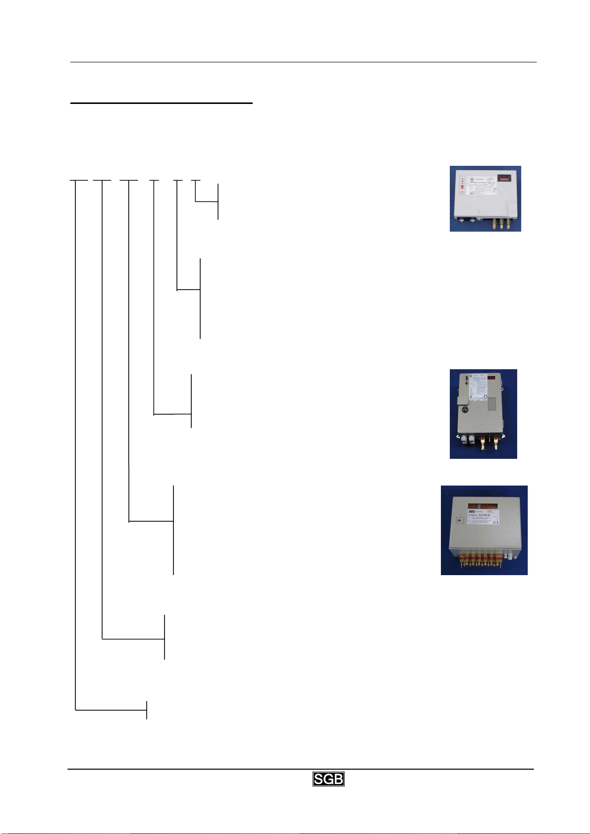
DL …. ELC (P) FC M
The leak detector’s ‘manometer’ design is
equipped with a digital pressure reading in
the housing’s lid.
The leak detector’s ‘filter control’ design is
equipped with a monitoring device for the dry
filter, which emits a separate status signal
when the dry material has been consumed.
It is only available for alarm pressures of up to
450 mbars.
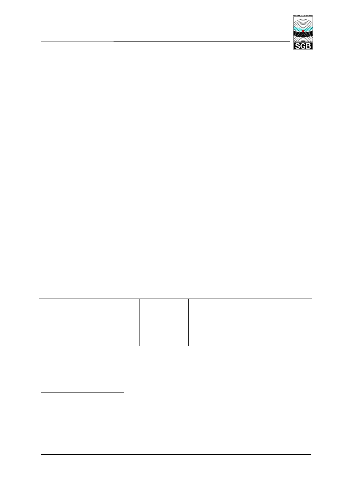
The leak detector’s ‘protected’ design is located
in a weatherproof housing.
Leak detectors for alarm pressures of 590 mbars
and higher are only available in this design.
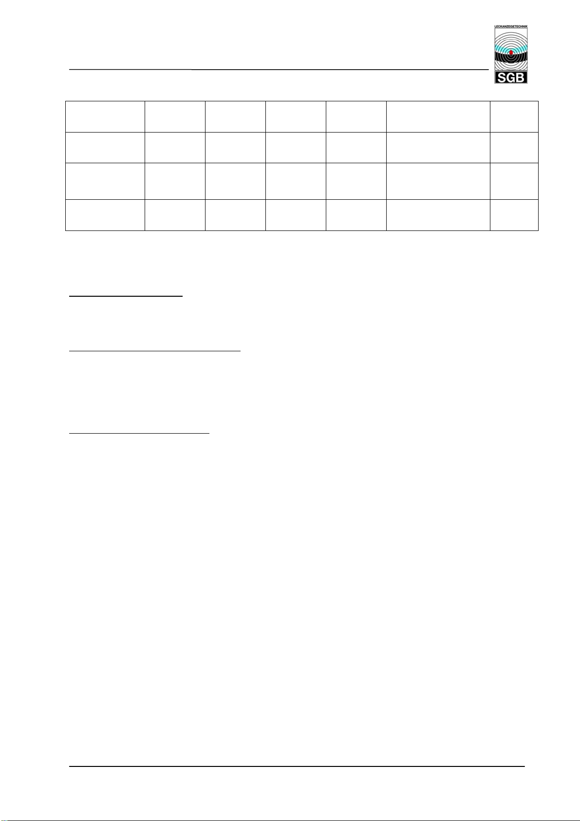
The leak detector’s 'economic leak control’ design
functions as both a leak detector and a leak reading
device: whereby the leak detector is equipped with
an integrated distribution for connecting up to 6
tanks.
This design is always weatherproof and the ’P’ is
therefore inapplicable.
‘Numerical values’ for the leak detector’s alarm
pressure.
The alarm pressures range from 50 mbars to 3,000
mbars.
The leak detector’s ‘pressure leak detector’ design works
at overpressure in relation to the atmospheric pressure.
01/09/2005. Your partner for leak detector equipment Sicherungsgerätebau GmbH, Siegen

4 von 49
OVERPRESSURE – LEAK DETECTOR DL ..
Contents Page
1 Subject
2 Field of application
2.1 Requirements for interstitial space 2
2.2 Tanks / interstitial space 2
2.3 Stored products 2
2.4 Exclusion 3
3 Description of functions 3
3.1 Switching and pressure values 3
3.2 Normal operation 3
3.3 Air or liquid leak 4
3.4 Air drying / Dry filter (DL.. ONLY) 4
3.5 Overpressure valve 4
3.6 Description of the display and control elements 4
4 Installation instructions 6
4.1 General 6
4.2 Personal protective equipment 7
4.3 Installation of the leak detector 7
4.4 Installation of the connection lines 7
4.5 Installation of the dry filter (DL.. ONLY) 8
4.6 Choice of pressure reducer (DLG.. ONLY) 8
4.7 Pressure cylinder and pressure reducer (DLG.. ONLY) 8
4.8 Electrical connection 9
4.9 Installation examples 9
5 Start up/servicing 9
6 Operating instructions 10
6.1 General 10
6.2 Maintenance 11
6.3 Intended use 11
6.4 Function test 11
6.5 Alarms 14
7 Removal 14
8 Marking 15
9 Abbreviations 15
DRAWINGS
Setting three-way valves P – 060 000
Installation example DL .. M1 + M2 – 060 000
Installation example DLG .. M3 + M4 – 065 000
Wiring diagram DL .. SL - 853 600
Wiring diagram DLG .. SL – 853 700
Test device P - 115 392
ANNEX:
B Switching and pressure values B – 1
TD Technical data TD – 1
26/01/2006
1

5 von 49
OVERPRESSURE – LEAK DETECTOR DL ..
1 Subject
Overpressure leak detector for double-walled tanks with pressure provided either by a pump or
by a compressed gas supply.
DL .. Overpressure leak detector with integrated pump. Dots stand for alarm pressure.
DLG .. Overpressure leak detector with compressed gas supply. Dots stand for alarm pressure
2 Field of application
2.1 Requirements for interstitial space
• Evidence of the pressure resistance of the interstitial space (see Annex B, column "p
TEST
"
minimum test pressure of the interstitial space)
• Evidence of the suitability of the interstitial space (for Germany: Building Inspectorate
Suitability Serification)
• Tightness of the interstitial space (see chap. 6.4.4)
• The number of interstitial spaces for monitoring in underground tanks depends on the total
interstitial space volume. According to prEN 13160, 8 m
3
must not be exceeded. It is
recommended not to exceed 4 m³ with regard to the feasibility of monitoring the tightness of
the interstitial space.
2.2 Tanks/interstitial space (see chapter 2.4)
• Under- and above ground double-walled steel or plastic tanks, without leak detection liquid
in the interstitial space, manufactured in the factory or on site, whose interstitial space is
suitable for the connection of a DL .. as per Annex B.
• Under- and above ground single-walled steel or plastic tanks with pressure-resistant leak
detection lining or leak detection jacketing, whose interstitial space is suitable for the
connection of a DL .. as per Annex B.
• Double-walled sumps or containments with interstitial space suitable for the connection of a
DL .. as per Annex B.
2.3 Stored products
Liquids hazardous to water with regard to the following points:
• The leak detection medium must not react with the stored products.
• Vapour/air mixtures resulting from the
- stored liquid
- stored liquid in combination with air / humidity or condensation
- stored liquid in combination with parts (materials) in contact with the liquid
must be classified in gas group IIA and II B and in temperature code T1 to T3.
26/01/2006
2

6 von 49
OVERPRESSURE – LEAK DETECTOR DL ..
2.4 Exclusion
If permeation occurs in the interstitial space as a result of the stored product and the material
structure of the inner tank wall (e.g. in double-walled GRP tanks) which can result in an
explosive atmosphere in the interstitial space under normal operating condition, ONLY leak
detector DLG .. must be used in combination with an inert leak detection medium (pressure
cylinder or operational network).
3 Description of functions
The overpressure leak detector DL .. resp. DLG .. monitors both walls of a tank for leaks. The
monitoring pressure is high so that any leaks above or below the liquid level (stored product and
ground water) are detected as a fall in pressure.
Pressure is built in up in:
DL .. by sucking in the outside air through the
integrated pump via a dry filter and forwarding it
to the interstitial space.
The dry filter dries the air to approx. 10%
humidity. Drying is necessary to prevent
moisture/condensation from collecting in the
interstitial space. Spent dry filter fillings must
be regenerated or replaced.
DLG .. by conveying compressed gas (dried air or
intert gas) to the interstitial space. The leak
detector has a display in the housing lid which
shows the operating pressure in the interstitial
space.
• Values under 50 mbar or under 0.73 PSI are
not shown.
• Values between 50 and 999 mbar are shown
in mbar without decimals.
• Values from 1 bar are shown in bar with 2
decimal places and from 10 bar with 1 decimal
place.
• Values in PSI are shown with 1 or 2 decimal
places.
3.1 Switching and pressure values
Annex B contains a list of the switching values.
3.2 Normal operation
The overpressure leak detector is connected by pressure and measuring line with the interstitial
space(s). The overpressure created by the pressure generator (pump or pressure cylinder) is
measured and controlled by a pressure sensor.
On reaching the operating pressure (refill OFF), the pressure generator (pump or solenoid
valve) is switched off. The pressure slowly falls again due to unavoidable leaks in the leak
detection system. On reaching the switching value for "refill ON", the pressure generator is
switched on again and operating pressure restored.
In normal operation, the leak detector swings between these two pressure values with short
operational times and longer standstill periods, depending on the level of tightness and
temperature fluctuations in the system.
26/01/2006
3
7 von 49
OVERPRESSURE – LEAK DETECTOR DL ..
3.3 Air or liquid leak
If a leak occurs below or above the liquid level or ground water, leak detection medium escapes
from the interstitial space. Pressure falls until the pressure generator is switched on to restore
the operating pressure. If the volume flow escaping out of the leak is greater than the refill
intake from the pressure generator, then the pressure in the system falls although the pressure
generator is activated.
Enlargement of the leak causes a further loss in pressure until the alarm pressure is reached.
The visual and audible alarm is triggered.
3.4 Air drying / dry filter (DL . ONLY)
The air fed to the interstitial space passes through a dry filter in the suction line. The dry filter
dries the air to approx. 10% humidity to prevent corrosion and accumulation of condensation
1
the interstitial space.
The dry filter is rated for twelve months as long as the system is used for its intended use and
there are no additional fluctuations in temperature.
A dry filter is orange when new and turns colourless (or green) when spent. Spent dry filters
must be replaced or regenerated without delay.
3.5 Overpressure valve
The overpressure valve integrated in the pressure line protects the interstitial space from
intolerably high overpressure (exceeding the test pressure).
Intolerably high overpressure can be caused among others by:
• increase in ambient temperature (e.g. direct sunshine)
• increase in temperature from hot filling (possibly consult manufacturer)
3.6 Description of the display and control elements
3.6.1 Status of the display elements (LEDs) for type DL ..
LEDs Operating status Alarm status Alarm, audible alarm
Unit out of order
switched off
in
OPERATION:
ON ON ON ON
green
ALARM: red
OFF ON FLASHES ON
1
Accumulation of condensation in the interstitial space can cause an intolerable pressure increase.
26/01/2006
4
8 von 49
OVERPRESSURE – LEAK DETECTOR DL ..
3.6.2 Status of the display elements (LEDs) for type DLG ..
LEDs Operating
status
OPERATION:
ON ON ON ON ON ON
Refilling
activated
Filling
activated
Alarm
status
Alarm, audible
alarm switched off
Unit out
of order
green
ALARM: red
PRESSURE
FEED: yellow
OFF OFF
OFF ON FLASHES ON ON OFF
OFF
FLASHES
2
ON
ON FLASHES ON
3.6.3 Operating functions through keys
For DL .. and DLG ..
Switch audible alarm off:
Press the button "Audible alarm" once briefly, audible signal switches off, red LED flashes.
Press again to switch the audible signal on.
This function is not available in normal operation and during malfunctions.
Testing the visual and audible alarm
Press and hold the button "Audible alarm" (approx. 10 sec.), the alarm is triggered until the button
is released.
This is only possible if pressure in the system has exceeded the "Alarm OFF" pressure.
2
on or off depending on pressure and/or audible alarm
26/01/2006
5
9 von 49
OVERPRESSURE – LEAK DETECTOR DL ..
DL .. DLG ..
Zero point adjustment3:
Three-way valve 21 in setting II (alarm triggered,
pump running)
Press and hold the button "Audible alarm" until
the "Alarm" LED flashes quickly (approx. 5 sec.),
release button, then press again and release.
Zero point adjustment is confirmed by 3 visual
and audible signals.
Three-way valve 21 in setting I
The zero point adjustment can only be repeated
after operating pressure has been built up.
Checking the tightness of the monitored system
Press and hold the button "Audible alarm" until
the "Alarm" LED flashes quickly, then release. A
value for tightness is shown when the "Alarm"
LED lights up (see chapter 6.4.5)
For this check, the leak detector must have
completed at least 1 automatic refilling interval in
normal operation (i.e. without filling with an
installation pump) for a meaningful statement.
Filling the interstitial space with leak detection
medium
Press and hold the "Filling" button for approx. 5
sec. until the yellow LED flashes. Filling is
activated.
On reaching the operating pressure, the yellow
LED goes off and filling stops.
When pressure falls because of pressure
compensation processes, filling can be activated
again to ensure that the interstitial space is filled
completely.
If you hold the button for longer than 10 sec., this
triggers the alarm. It goes off again just after you
release the button.
Checking the tightness of the monitored system.
Press and hold the button "Audible alarm" until
the "Alarm" LED flashes quickly, then release. A
value for tightness is shown when the "Alarm"
LED lights up and is also shown in the display
(see chapter 6.4.5)
10 sec. after the value is displayed, the leak
detector goes back to normal operation.
For this check, the leak detector must have
completed at least 1 automatic refilling interval in
normal operation (i.e. without activating the filling
function) for a meaningful statement.
4 Installation instructions
4.1 General
(1) Installation only by qualified companies
(2) Comply with pertinent accident prevention regulations.
(3) Comply with the ex regulations (if necessary) such as BetrSichV [Operational Safety
Ordinance] or others.
(4) Before inspecting control shafts, check the oxygen level and scavenge the control shaft if
necessary.
DLG ONLY
(5) When transporting the pressure cylinder to and from the site, always comply with the
corresponding traffic regulations.
(6) Secure the pressure cylinder on site to prevent it from falling over.
3
Only applicable for DL 50 to DL 450.
4
For Germany: qualified companies as per § 19l WHG [Water Resources Act] with skills and know-how
when it comes to fire and explosion protection.
4
.
26/01/2006
6

10 von 49
OVERPRESSURE – LEAK DETECTOR DL ..
(7) If start up/operation takes place in enclosed rooms, ensure that there is adequate
ventilation. Affix a warning sign.
4.2 Personal Protective Equipment
The items listed here refer in particular to safety when working on systems which may be
subject to risk of explosion.
When working in potentially explosive areas, at least the following items of equipment are
required:
• Suitable clothing (risk of electrostatic charge)
• Suitable tools (as per EN 1127)
• Suitable gas detectors for the prevailing vapour/air mixtures (work should only be carried out
at concentrations 50% below the lower flammable limit
5
)
• Instruments for measuring the oxygen level in the air (Ex / O-meter)
4.3 Installing the leak detector
(1) Mounted to the wall usually with plugs and screws.
(2) In a dry room, or in the open air in a suitable protective box.
(3) Installation in protective box: additional external signal or alarm forwarding via dry relais
contacts to central control desk or similar device.
(4) NOT in potentially explosive areas.
(5) The distance between leak detector and interstitial space should be kept as short as
possible.
4.4 Installation of connection lines (between leak detector and tank)
(1) Metal (usually copper) or plastic tubes with pressure resistance at least equal to the test
pressure of the interstitial space, the same applies to fittings and screwed unions. (Note
temperature range, particularly when using plastic).
(2) Inside clearance min. 4 mm for inert gas as leak detection medium
min. 6 mm for air as leak detection medium
(3) Should not be much longer than 50 m. If longer than 50 m, use tube/hose with larger inside
clearance using corresponding adapters.
(4) Colour coding: Measuring line: red
Pressure line: white (or clear)
(5) The full cross section must be maintained. No squeezing or bending
6
.
(6) Metal or plastic tubes underground or plastic tubes installed outside above ground must be
routed in conduits.
5
Other percentages are possible based on national or company regulations.
6
If necessary, use commercially available moulded pieces (with stipulated bending radii) for plastic tubes.
26/01/2006
7

11 von 49
OVERPRESSURE – LEAK DETECTOR DL ..
(7) Seal conduits to be gas-tight with protection from penetration of liquids.
(8) Avoid build-up of static electricity (e.g. when inserting and routing tubes).
(9) Details for connecting systems, see worksheet AB-820 500
4.5 Installation of the dry filter (DL .. ONLY)
(1) As close as possible to the leak detector. If the leak detector is mounted in a protective
box, the dry filter can be installed in the protective box or in the open air.
(2) Vertical with intake opening at the bottom, using enclosed installation material.
(3) Connect the dry filter to the leak detector intake port with a PVC hose (or similar).
4.6 Choice of pressure reducer (DLG ..ONLY)
(1) The pressure reducer must have an integrated overpressure valve.
(2) The range for the pressure reducer must be selected according to the specific application
respectively adjusted pressure (see Annex B).
4.7 Pressure cylinder and pressure reducer (star up/function test) (DLG .. ONLY)
(1) After the pressure cylinder has been set up securely, remove the protective cover.
(2) Fit the pressure reducer to the cylinder.
(3) Close the shut-off cock on the pressure reducer.
(4) Install the connecting tube between leak detector and pressure reducer.
(5) Turn pressure control valve all the way back.
(6) Open bottle shut-off cock (poss. leak test between pressure reducer and bottle)
(7) Adjust pressure at pressure reducer as per Annex B using pressure control valve on
pressure reducer (poss. readjust during pressure build-up).
(8) To change the pressure cylinder:
- Close the shut-off cock on the pressure reducer.
- Close the bottle shut-off cock.
- Remove the pressure reducer from the cylinder (caution: gas escapes until pressure is
relieved in the pressure reducer)
- Put protection cover on the cylinder.
- Erect and secure new cylinder, remove protection cover.
- Fit the pressure reducer (poss. leak test between pressure reducer and cylinder)
- Open bottle shut-off cock.
- Open shut-off cock on pressure reducer, poss. readjust pressure using the pressure
control valve.
26/01/2006
8

12 von 49
OVERPRESSURE – LEAK DETECTOR DL ..
4.8 Electric connection
(1) Power supply: according to label
(2) Permanent installation, i.e. no plugged or switched connections.
(3) Comply with the regulations issued by the utility company.7
DL .. DLG ..
(4) Terminal configuration: (see also SL-853
600)
1 / 2 Mains connection
3 / 4 Occupied (internal pump)
5 / 6 External signal (in an alarm, a line
voltage present here, stopped
by pressing button "Audible
alarm").
11 / 12 Dry relay contacts (opened on
alarm and power failure).
(4) Terminal configuration: (see also SL-853
700)
1 / 2 Mains connection
3 / 4 Occupied (internal solenoid)
5 / 6 External signal (in an alarm, a line
voltage here, stopped by pressing
button "Audible alarm".
11 / 12 Dry relay contacts (open
on alarm and power failure)
21 / 22 Occupied (internal sensor)
4.9 Installation examples
Installation examples are shown in the Annex
5 Start up/servicing
(1) Observe also the instructions in chapter 4.
(2) Special safety measures are required when commissioning a leak detector in an already
filled tank (e.g. check that there is no gas in leak detector and/or interstitial space). Other
measures can depend on local conditions at the discretion of the staff.
(3) After completing the pneumatic connection, proceed with the electrical connection.
(4) Check that the LEDs "Operation" and "Alarm" light up and that the audible alarm works.
Press the button "Audible alarm".
(5) Three-way valve 21 in position "III", connect test instrument.
DL ..
(6) Apply operating pressure to leak detection
system as per table on page 3 (use
installation pump with adequately
dimensioned dry filter or nitrogen pressure
cylinder).
(7) Pressure can be built up with the installation
pump directly using the pressure line or via
the three-way valve 20 (position IV).
Note: If pressure cannot be built up with the
7
For Germany: also VDE regulations
DLG ..
(6) Press and hold "Fill" button for approx. 5
secs. until yellow LED flashes. The solenoid
valve opens to fill the interstitial space
quickly. On reaching the operating
pressure, filling stops and the yellow LED
goes off.
For very large interstitial spaces, it may be
necessary to change the cylinder (see
chapter 4.6).
Note: If pressure cannot be built up in spite of
26/01/2006
9

13 von 49
OVERPRESSURE – LEAK DETECTOR DL ..
connected installation pump, find and
eliminate the leak (poss. check capacity of
installation pump, check correct setting of
pressure reducer).
the connected pressure cylinder, find and
eliminate the leak (poss. check correct setting of
pressure reducer). CAUTION: Leak detector
display begins at 150 mbar pressure.
(7) Filling can (should) be activated again to
ensure that the interstitial space is filled
completely.
(8) On reaching the leak detector operating pressure (pressure generator in leak detector
switches off), install pressure tube again or set both valves to setting "I". Remove pressure
instrument.
(9) Check functions as per chapter 6.4
6 Operating instructions
6.1 General
(1) Following impervious, correct connection of the leak detection system, the leak detector
can be presumed to work in the normal range.
(2) If the pressure generator switches on frequently or runs continuously, this indicates leaks
which must be eliminated in an appropriate period of time.
(3) An alarm always indicates a major leak or defect. Find and eliminate the cause quickly.
(4) The operator must regularly check that the "Operation" LED is working properly.
(5) Disconnect the leak detector from the power supply before performing and repair work.
(6) The operating lamp goes off when there is a circuit failure: the dry relay contacts open.
(7) (DL .. ONLY). When the filter filling changes colour from orange to colourless (or green),
it must be replaced or regenerated.
6.2 Maintenance
6.2.1 By the operator:
(1) Check the dry filter regularly
8
. When it changes colour from orange to colourless (or green),
replace or regenerate the filter filling.
(2) Check the filling in the pressure cylinder regularly. If the pressure is only just above the
pressure setting on the pressure reducer, refill or replace the cylinder.
6.2.2 Maintenance work and function check by qualified experts
8
Recommended: min. at 2 monthly intervals
9
For Germany: experts for installation/service of leak detectors or in the responsibility of an expert,
according to the currently valid regulations.
9
.
26/01/2006
10

14 von 49
OVERPRESSURE – LEAK DETECTOR DL ..
(1) Once a year to ensure functional and operational safety.
(2) Scope of inspection as per chapter 6.4
(3) Also check compliance with the conditions in chapter 4.5 and 6.2.
6.3 Intended use
• Groups of interstitial space only for underground interstitial spaces.
• Double-walled tanks, sumps or containments whose walls on the stored product side are
resistant to permeation from particles which can generate potentially explosive vapours.
EXCEPTION:
Inner walls not resistant to permeation when using an inert leak detection medium.
• The alarm pressure must be min. 30 mbar higher than any pressure occurring in the
interstitial space (from inside and/or outside).
• Grounding (where applicable) according to valid regulations
10
.
• Leak detection system is impermeable, according to chapter 6.4.6 of this documentation.
• Mount the leak detector outside potentially explosive area.
• Lead-throughs for the pneumatic hoses are sealed gas tight.
• Leak detector (electric) is connected so that it cannot be switched off.
6.4 Function test
Check functional and operational safety
• every time after start up
11
• on the basis of chapter 6.2 in the intervals stated there
• every time after troubleshooting
6.4.1 Test scope
(1) Poss. check the scope of work with the person responsible on site.
(2) Comply with the safety regulations for handling the specific stored product.
(3) (DL .. ONLY) Regeneration/replacement of the filter filling.
(4) Check the free passage of air (gas) in the interstitial space (chapter 6.4.2).
(5) Check the switching values with the test unit (chapter 6.4.3),
alternatively: check the switching values without test unit (chapter 6.4.4)
(6) Check the overpressure valve (chapter 6.4.5).
(7) Tightness test (chapter 6.4.6).
(8) Restore operating condition (chapter 6.4.7).
(9) Test report confirming functional and operational safety to be compiled by the qualified
person.
10
e.g. EN 1127
11
For Germany; otherwise comply with the national regulations (e.g. VAwS)
26/01/2006
11

15 von 49
OVERPRESSURE – LEAK DETECTOR DL ..
6.4.2 Check the free passage of air (gas) in the interstitial space
(1) If several interstitial spaces are manifolded together, check the free passage of each
interstitial space on its own:
(2) If several interstitial spaces are connected to a manifold with shut-off cocks in the pressure
and measuring lines, close all shut-off devices at the distribution units.
(3) Connect measuring gauge at three-way valve 21, setting "III".
(4) Three-way valve 20 in setting "IV". The (corresponding) interstitial space is vented.
CAUTION: maintenance work and function checks only by qualified persons. If inert gas is
used as leak detection medium, ensure there is adequate ventilation!
(5) Open shut-off cocks of the first (following) tank (measuring and pressure lines in pairs).
(6) Ascertain the pressure loss on the measuring gauge. If there is no pressure loss, find and
remedy the cause.
(7) Close the shut-off cocks opened under paragraph (4).
(8) Proceed with steps (5) to (7) with every other tank.
(9) Three-way valve 20 and 21 in setting "I", remove measuring gauge.
(10) Open all shut-off cocks on the manifold with connected tanks.
6.4.3 Checking the switching values with test unit.
(1) Connect the test unit to the test port of three-way valve 20 and 21. Both valves in setting
"II"“.
(2) Connect measuring gauge to the test unit.
(3) Close needle valve (test unit), pressure is built up to operating pressure.
(4) Vent using the needle valve, ascertain switching values for "Pump ON" and "Alarm ON"
(visual and audible), note values.
(5) Close needle valve and ascertain switching values for "Alarm OFF" and "Pump OFF". Note
values (possibly open needle valve slightly for slow increase in pressure)
(6) Three-way valve 20 and 21 in setting "I", remove measuring gauge.
6.4.4 Checking the switching values without test unit
(1) If several tanks are connected by a manifold, close all the shut-off cocks on the manifold
apart form the valves for the tank with the smallest interstitial space.
(2) Connect measuring gauge to three-way valve 21, setting "III".
(3) Vent via three-way valve 20 (setting "III"), ascertain switching values for "Pump ON" and
"Alarm ON" (with visual and audible alarm), note values.
(4) Three-way valve 20 in setting "I", ascertain switching values for "Alarm OFF" and "Pump
OFF", note values
(5) Three-way valve 21 in setting "I", remove measuring gauge.
(6) Open all shut-off cocks on the manifold with connected tanks.
26/01/2006
12
 Loading...